1. Introduction
Unmanned underwater vehicles (UUVs) have evolved into essential platforms for marine environmental monitoring and resource exploration due to their operational flexibility and adaptability to diverse conditions (Roh et al. Reference Roh, Song, Kim and Park2025). However, current UUV development faces critical constraints from limited onboard energy storage. Research indicates that frictional resistance accounts for 70 % of total hydrodynamic resistance during underwater operations (Zhai et al. Reference Zhai, Zhang, Wang, Cheng, Wang, Wang, Li, Zhang and Li2024). Drag-reduction technologies are essential for improving energy efficiency. The current underwater drag-reduction technology primarily focuses on the following three methods: superhydrophobic, microbubble and micro-riblet drag reduction. As for the first two methods, the former faces a dual failure mechanism: gas-film instability under high-speed/high-pressure conditions compromises drag reduction (Zhu et al. Reference Zhu, Song, Gao, Dong, Xu, Liu, Zheng, Zhou and Liu2024), while surface microstructures may amplify turbulence bursts, inducing drag increments (Wang et al. Reference Wang, Tang, Cai, Tong and Xiong2018); the latter (Madavan et al. Reference Madavan, Deutsch and Merkle1985) has confronted persistent challenges in maintaining bubble stability and controlling bubble formation within deep-water environments.
Micro-riblet drag-reduction technology modifies surface microstructures to reduce drag. Initial studies revealed that micro-ridged skin (placoid scales) on fast-swimming sharks reduces hydrodynamic drag, improving swimming efficiency. Walsh (Reference Walsh1982, Reference Walsh1990) at NASA reported a 6 %–8 % reduction in drag on aircraft surfaces using riblet films, while Monfared (Reference Monfared2020) achieved a 7 % reduction in a towing tank experiment with blade-type riblets.
Riblet drag-reduction research converges on three critical dimensions:
-
(i) Riblet geometric shape optimisation: research shows optimal drag reduction relies on riblet–turbulence interactions, fluid properties and riblet geometry and size (Rouhi et al. Reference Rouhi, Endrikat, Modesti, Sandberg, Oda, Tanimoto, Hutchins and Chung2022; Chen et al. Reference Chen, Liu, Cui, Zhang and Chen2023; Liu et al. Reference Liu, Wang, Hu and Liu2023). Over the past few decades, researchers have continuously optimised various geometric sizes and shapes of riblets to achieve maximum drag reduction. Early on, Walsh (Reference Walsh1982, Reference Walsh1990) proposed dimensionless parameters to characterise riblet geometry, and research found that riblets only exhibit drag-reduction effects within specific parameter ranges. Specifically, when the dimensionless riblet span
 $s^{+}$
= 16 and the dimensionless riblet spacing
$h^{+}$
= 8, the drag reduction reaches its peak at 8 %. Bechert et al. (Reference Bechert, Bruse, Hage, Van Der Hoeven and Hoppe1997) simulated various V-riblet structures and observed both drag-reduction and drag-increase phenomena under a range of parameters. Qiu et al. (Reference Qiu, Chauhan and Lei2020) conducted numerical simulations of V-riblets, trapezoidal riblets and semicircular riblets, indicating that semicircular riblets offer the best drag reduction.
-
(ii) Drag-reduction mechanism exploration: many scholars have used visualisation techniques to analyse the flow field near riblets, attempting to explain the reasons. Bechert & Bartenwerfer (Reference Bechert and Bartenwerfer1989) proposed a drag-reduction mechanism based on protrusion height, suggesting that riblets hinder the cross-flow of the viscous sublayer, thereby reducing wall shear stress. Bacher et al. (Reference Bacher and Smith1985) proposed the second vortex theory, pointing out that the secondary vortex at the top of the riblet can suppress the lateral movement of the low-speed band. However, the current drag-reduction mechanism of riblets is not yet fully elucidated.
-
(iii) Fabrication method improvement: initially, biomimetic methods like biological skin replication were used, such as Chen et al. (Reference Chen, Zhang, Ma, Che, Zhang and Sudarshan2014), who replicated biomimetic shark skin using soft lithography technology, achieving excellent drag-reduction effects. With the advent of high-tech, laser etching and 3D printing technologies have emerged. Johannes Oeffner (Reference Johannes Oeffner2012) utilised laser etching to prepare micro-structured surfaces, reducing the turbulent flow pressure drop. Wen (Reference Wen, Weaver and Lauder2014) used micro-computed tomography scanning and 3D printing to synthesise shark skin membranes, achieving an 8.7 % drag reduction at low speeds, although it may increase drag at high speeds.


However, these traditional methods present significant challenges for the efficient and cost-effective production of riblet surfaces. By contrast, the controlled buckling of hard films on soft substrates can create adjustable wrinkle patterns (Wang & Zhao Reference Wang and Zhao2016). This approach is characterised by its low cost and streamlined fabrication process. Currently used in surface engineering for processing, applications include optoelectronics, stretchable electronics, wettability/anti-fouling surfaces, microchannels and cell growth/movement (Chang et al. Reference Chang, Jiang, Chen and Chiang2021; Li et al. Reference Li, Zhang, Su, Li, Wang, Dong, Xu, Ma, Yin and Jiang2023; Zhang et al. Reference Zhang, Zhang, Yan, Wang and Yuan2023). Initially, Bowden et al. (Reference Bowden, Huck, Paul and Whitesides1999) conducted experiments in which they sequentially deposited a titanium interlayer and a gold film on a polydimethylsiloxane (PDMS) surface at 110 °C. Upon cooling, the PDMS contracted, causing the gold film to buckle and form micron-scale wrinkle stripes. In his subsequent research, he also found that the wavelength and amplitude of wrinkles could be controlled by adjusting the temperature and plasma oxidation time. Huang, Hong & Suo (Reference Huang, Hong and Suo2004) revealed through numerical simulations that, depending on the differences in loading along various axes, the system could form complex wrinkle patterns such as chevron and checkerboard patterns. Subsequent research focused on the influence of substrate pre-stretching. Cao & Hutchinson (Reference Cao and Hutchinson2012) conducted numerical simulations of the film/substrate system under various conditions with and without pre-stretching. The results showed that, without pre-stretching, the instability mode varied with the modulus ratio μf/μs of the film to the substrate. With large pre-stretching, a new ridge pattern emerged after the secondary bifurcation, which alleviated the compression of surrounding wrinkles and reduced the amplitude. Zang et al. (Reference Zang, Zhao, Cao and Hutchinson2012) summarised and verified the previous findings, clarifying that the ridge pattern would only appear when the pre-stretching γ > 1.4.
Traditional methods encounter challenges in achieving low-cost, straightforward and rapid fabrication of riblet surfaces. Instead, by inducing buckling in hard thin films on soft substrates through physical and chemical means, regular and finely striped structures can be produced. This approach is simple, rapid and economical, and the resulting structures have been widely applied in fields such as surface engineering. Nevertheless, this approach has yet to be applied in the development of drag-reduction structures.
This paper proposes a method using ultraviolet (UV)-induced bending on pre-stretched PDMS to fabricate drag-reduction surfaces. Additionally, we conduct experimental and numerical simulation studies on the riblet surfaces formed through buckling instability. This study analyses and validates the effects of drag reduction and investigates the underlying mechanisms. The findings of this research provide data support for future applications in drag reduction.
2. Design and fabrication of regular riblet surfaces
According to Walsh’s (Reference Walsh1990) findings, the drag-reduction efficiency of riblets is strongly influenced by their depth and spacing. Accordingly, this study examines PDMS buckling and factors influencing riblet formation to develop an optimised, patterned riblet surface for enhanced drag reduction.
2.1. Mechanical modelling of surface microstructures
In order to generate the necessary material data for subsequent experiments, we examined the mechanical characteristics of the soft substrate as well as those of the rigid film, which together comprise the modified PDMS system.
2.1.1. Mechanical properties and constitutive equation of the soft substrate
Given the elastomeric and nonlinear nature of PDMS, an electronic universal tensile testing machine was employed to characterise the stress–strain response of the soft substrate film. The sample ends were secured to the grips of the testing machine. Reflective strips were placed on the measurement area. This allowed the extensometer to detect elongation accurately. Subsequently, both the tensile testing machine and the extensometer were activated, and data were recorded throughout the test.
Elastic modulus and stress–strain area diagram of specimens S1–S5.

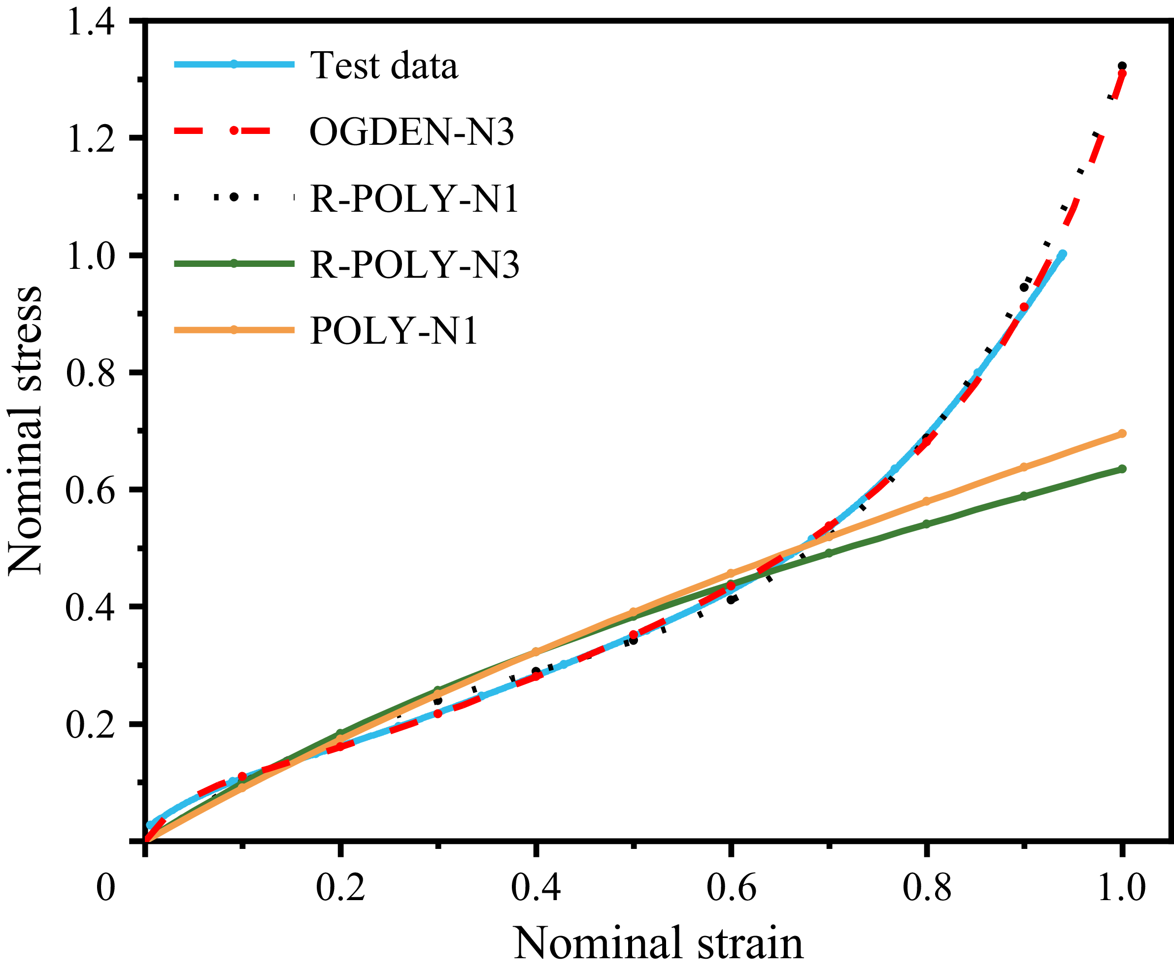
In this experiment, five samples were analysed, figure 1 displays the elastic modulus and the areas under the stress–strain curves for five sets of specimens. The maximum relative error of the elastic modulus is 5.95 % with a coefficient of variation (CV) of 4.16 %, while the maximum relative error of the stress–strain curve area is 5.82 % with a CV of 4.77 %. Both sets of data exhibit low dispersion and high reliability, indicating that averaging the stress–strain curves across the five specimen sets yields a representative characteristic curve. The resultant data were subsequently fitted using ABAQUS software, and the fitted curves were compared with the constitutive curves of various elastomeric materials, as shown in figure 2. The analysis showed that the OGDEN refers to the Ogden hyperelastic material model (Ogden, Reference Ogden1972) best captured the actual PDMS stress–strain behaviour. Therefore, we adopted the OGDEN constitutive model for further numerical analyses. The constitutive equation for the Ogden-N3 elastomeric material, as presented by Ogden (Reference Ogden1972), is given in (2.1)
 \begin{equation} W=\sum _{i=1}^{N}\frac{\mu _{i}}{\alpha _{i}}\left(\overline{{\lambda }_{1}^{\alpha _{i}}}+\overline{{\lambda }_{2}^{\alpha _{i}}}+\overline{{\lambda }_{3}^{\alpha _{i}}}-3\right) + \sum_{k=1}^{n}\frac{1}{D_{k}}\left(J-1\right)^{2k} \!. \end{equation}
The parameter N denotes the order of the model. In this paper, N is set to 3. Also,
 $\mu _{i}$
denotes the shear modulus in pressure and
 $\alpha _{i}$
denotes the strain-hardening exponent, which is a dimensionless quantity,
 $\overline{\lambda _{i}}$
is the partial elongation, J is the relative volume ratio and
 $D_{k}$
is an incompressible parameter used to indicate the volume change.
2.1.2. Mechanical properties of the rigid oxide film
Figure 3 illustrates the effect of UV irradiation duration on the surface thickness of hard films. Cross-sectional measurements for each sample group were acquired using an optical microscope, and the data were plotted based on the mean values from five independent samples. The results show that film thickness increases with longer UV exposure. Error bars represent the standard deviation from five replicate experiments. They further validate the reliability of these findings.
PDMS material intrinsic fitting curve.

Average thickness of the hard film under different UV exposure times.

A nanoindentation apparatus was used to assess the film’s stiffness. In this study, five measurements were conducted at different orientations on a single sample. As illustrated in the figure 4, the measured data exhibit significant fluctuations when the indentation depth is below 600 nm, likely due to the sample’s surface roughness. With further increases in indentation depth, the probe penetrates into the oxide layer, and the data stabilise, maintaining an average modulus of approximately 200 MPa. In subsequent numerical simulations, the elastic modulus of the hard film was set at 200 MPa, and Poisson’s ratio was assigned a value of 0.27.
Oxide layer continuous stiffness test curve.

Evolution of secondary bifurcation patterns in the system for the two pre-stretching cases. (a) Evolution of the secondary bifurcation pattern when the substrate is unstressed. (b) Evolution of the secondary bifurcation pattern in the system at a substrate pre-stretch value of 0.4.

2.2. Design of regular riblet surfaces
2.2.1. Pre-stretching and riblet formation
Film buckling involves complex geometrical nonlinearities. To simulate the instability in the substrate/film system, we constructed a two-layer model using ABAQUS software.
The applied displacement load was adjusted according to the pre-stretch ratio. When the substrate was unstretched, this adjustment was not applied. During the stress-release simulation, an inverse displacement load of equal magnitude was applied in the transverse direction. To replicate the instability process in the uniformly continuous model, an appropriate damping factor was introduced, which was set to 0.002 by default.
Numerical simulations were performed to analyse the evolution of secondary bifurcations under both pre-stretch and non-pre-stretch conditions.
In the simulation shown in figure 5, bifurcation characterised by a sine-like wrinkling pattern occurs at a compressive strain of 0.03. As the compressive strain increases, the surface wavelength shortens while the amplitude grows. When the compressive strain reaches 0.165, the aspect ratio of the striped wrinkles A/λ peaks at 0.2, where A denotes the amplitude (height) of the ridge-type riblet structures in the aspect ratio A/λ. At a compressive strain of 0.17, secondary bifurcation results in a period-doubling mode. In contrast, when the substrate is pre-stretched (γ = 0.4), a regular periodic ridge structure emerges on the system’s surface at a compressive strain of 1.27. When the compressive strain is increased to 0.4, the aspect ratio of the periodic ridge structure (A/λ = 0.4) surpasses the maximum value observed in the non-pre-stretched state.
The pre-stretched film/substrate system produces periodic ridge patterns with high aspect ratios as a result of secondary bifurcation. According to Walsh (Reference Walsh1982, Reference Walsh1990), Bechert et al. (Reference Bechert, Bruse, Hage, Van Der Hoeven and Hoppe1997) and Martin & Bhushan (Reference Martin and Bhushan2014), high-aspect-ratio ridge-riblet structures can reduce drag significantly. However, if the aspect ratio gets too high, these structures might increase drag. The optimal range for the aspect ratio is between 0.4 and 0.5. Therefore, pre-stretching the substrate is essential for fabricating ridge-riblet structures.
2.2.2. Effects of pre-stretching and UV exposure on riblet formation
The experimental procedure comprised the following steps. Initially, the PDMS films were ultrasonically cleaned for 15 min to ensure surface cleanliness. Subsequently, the films were mounted on a tensile platform under designated displacement loads and exposed to UV light for varying durations. After the prestress was released, a super-depth microscope was used to analyse the surface morphology. To further elucidate the effects of pre-stretch values and UV irradiation time on the surface morphology, a series of detailed experiments was conducted:
-
(i) The PDMS films with different pre-stretch values were irradiated for 50 min and analysed after stress release to study the final positioning modes.
-
(ii) The PDMS films with varying pre-stretch values were subjected to UV irradiation for 30, 40 and 50 min. Surface morphologies were then compared.
The results in figure 6 reveal that sinusoidal wrinkles dominate when pre-stretch values range from 0.13 to 0.33. As pre-stretch increases, wavelengths shorten and amplitudes grow. Between 0.33 and 0.43, ridge patterns appear, with both wavelengths and amplitudes varying inversely. For pre-stretch at 0.48, regular ridge structures are prevalent, although localised regions show period-doubling patterns. Beyond 0.50, period doubling dominates.
From table 1, the optimal riblet pattern, characterised by a maximum aspect ratio of 0.4, occurs at a pre-stretch of 0.43. To maximise aspect ratios while avoiding period doubling, the pre-stretch should be controlled near 0.45.
The thickness of the hard oxide layer is directly influenced by the duration of UV exposure. To investigate this relationship, PDMS samples with varying pre-stretch values were subjected to UV irradiation for 30, 40 and 50 min.
Figure 7 illustrates the relationship between surface geometry and exposure duration. Both the amplitude and wavelength of the ridge structures increase with the hard oxide layer thickness. Increasing the film thickness boosts the maximum achievable pre-stretch value. This increase effectively suppresses period doubling on the surface.
Aspect ratios of riblet surfaces at different pre-stretch values.

Table 1. Long description
A table with two rows and five columns. The first row is labeled ‘Pre-stretch values’ and contains the values 0.13, 0.2, 0.3, and 0.43. The second row is labeled ‘Aspect ratio’ and contains the values 0.2, 0.27, 0.33, and 0.4. The table compares the aspect ratios of riblet surfaces at different pre-stretch values. Each pre-stretch value corresponds to a specific aspect ratio, showing how the aspect ratio changes with varying pre-stretch values.
System surface wrinkling for pre-stretch values
 $\gamma =013,0.20,0.33,0.43,0.48,0.50$
.

Variation of ridge-type riblet dimensions for different irradiation times. (a) Relationship between riblet amplitude and UV irradiation time. (b) Relationship between riblet wavelength and UV irradiation time.

2.3. Fabrication process of regular riblet surfaces
Based on previous findings, pre-stretching PDMS using the right stretch ratio and controlled UV exposure consistently produces regular riblet structures with high aspect ratios. However, these structures have a convex profile. To further reduce drag and more accurately emulate natural bionic architectures, it is necessary to invert the convex profile into a concave configuration through moulding techniques.
Figure 8 illustrates the fabrication process. The fabrication process commences with the sheet as the starting material, which is pre-stretched to a draw ratio of λ = 0.43 at a rate of 50 mm min−1 which is pre-stretched to a ratio of A/λ. After stretching, the PDMS is irradiated for 40 min using UV irradiation.
Schematic diagram of the fabrication process of ridge-riblet surfaces.

Figure 8. Long description
A diagram illustrating the fabrication process of ridge-riblet surfaces. The process begins with a pre-stretched soft substrate. This substrate is subjected to UV irradiation while being stretched, which causes a hard film to form on its surface. The substrate is then released from its stretched state, resulting in the formation of riblet surfaces. The next step involves casting silicone, specifically PDMS, onto the riblet surfaces using a mold labeled E630B. Finally, the silicone is demolded, producing the final riblet surfaces.
Distribution of spacing and depth dimensions of riblets across different specimens.

Next, the PDMS surface attached to the acrylic plate is positioned within a mould. A silicone elastomer (E630B) is prepared by thoroughly mixing its components in a 1 : 1 ratio. To eliminate entrapped air bubbles, the mixture is degassed in a vacuum dryer for 5 min. Prior to pouring, a release agent is applied to the PDMS surface to facilitate subsequent separation. Finally, the degassed silicone is poured into the mould and left to cure without disturbance.
To reduce the impact of fabrication errors on the test results, this study first selected five ridge-riblet surfaces measuring 5 cm × 5 cm × 0.5 mm. These small samples were used to quantitatively measure the riblet width and height. They also served as a theoretical basis for fabricating and characterising larger samples (5 cm × 20 cm). Because microscopic observation has a limited field of view, there might be dimensional differences between riblets at the edges and those in the interior. To address this issue, we used a regional cutting and sampling strategy. We cut the specimens into slender strips at 1 cm intervals along the riblets’ direction. Then, we randomly selected ten characteristic measurement points within the riblet area of each strip. This method ensured an accurate determination of the geometric dimensions.
The dimensional data from five specimens (S1–S5), as shown in the figure, were used to evaluate the repeatability precision of the fabrication process. Specifically, the measured riblet depth (h) values stabilised at approximately 33 μm, with individual specimens exhibiting a maximum CV of 6.74 %. Similarly, the measured riblet spacing (s) values were concentrated around 79 μm, with the maximum CV for individual specimens also reaching 4.59 %. Overall, the fabrication process demonstrates high repeatability and precision.
The final product is a ridge-riblet surface measuring 20 cm × 5 cm × 0.5 mm, with riblets exhibiting depths of 33 μm and spacings of 79 μm. As depicted in figure 10, this structure fulfils the necessary criteria for effective drag reduction while maintaining compatibility with bionic design principles.
Actual surface image of riblet structures; (a) side view, (b) top view.

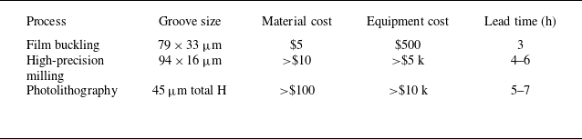
Figure 11 shows the fabrication workflows for three drag-reducing methods. The photolithography process uses six detailed steps. These include substrate pretreatment, photoresist coating and baking. It then requires other steps that rely on high-precision photolithography and etching equipment. The high-precision milling method has four steps. These steps include substrate preparation and cutting. In contrast, the thin film buckling process uses only four core steps. It involves pre-stretching the substrate. This method eliminates the need for complex operations or high-precision equipment.
Informed by recent studies (Hamilton et al. Reference Hamilton, Tutunea-Fatan and Bordatchev2022; Thakur & Fridman Reference Thakur and Fridman2022; Zhou et al. Reference Zhou, Yan, Zhang, Zhou, Ou, Lv, He and Yuan2022; Todd & Krasnogor Reference Todd and Krasnogo2023), table 2 is constructed to provide a comparative analysis of five key manufacturing indicators for drag-reducing surfaces. The film buckling method demonstrates significant overall performance advantages, with material costs as low as USD 5 and equipment investments down to USD 500 – both markedly lower than those required for high-precision milling and photolithography techniques. Moreover, this method eliminates the need for an etching process and is not constrained by the size limitations typically imposed by high-precision equipment, thereby enhancing manufacturing efficiency.
Performance parameter comparison of three drag-reducing surface preparation methods (estimated values) (Hamilton et al. Reference Hamilton, Tutunea-Fatan and Bordatchev2022; Thakur & Fridman Reference Thakur and Fridman2022; Zhou et al. Reference Zhou, Yan, Zhang, Zhou, Ou, Lv, He and Yuan2022; Todd & Krasnogor Reference Todd and Krasnogo2023).

Table 2. Long description
A table comparing performance parameters of three drag-reducing surface preparation methods. The table has five rows and four columns. The columns are labeled Process, Groove size, Material cost, Equipment cost, and Lead time (h). The rows are labeled with the processes: Film buckling, High-precision milling, and Photolithography. Row 1: Film buckling, 79 x 33 micrometers, 5 USD, 500 USD, 3 hours. Row 2: High-precision milling, 94 x 16 micrometers, more than 10 USD, more than 5000 USD, 4-6 hours. Row 3: Photolithography, 45 micrometers total height, more than 100 USD, more than 10000 USD, 5-7 hours.
Process flow diagrams of three drag-reducing surface preparation methods.

Figure 11. Long description
A flowchart illustrating three methods for preparing drag-reducing surfaces. The flowchart is divided into three main sections, each representing a different method: high-precision milling, thin film buckling, and photolithography. Each method is depicted as a sequence of steps, represented by rectangles, leading to the final outcome. Panel A: High-precision milling. The process starts with high-precision milling, followed by substrate preparation and cutting. Next, clamping and alignment are performed, followed by the milling process. The final step is surface finishing. Panel B: Thin film buckling. The process begins with thin film buckling, followed by substrate pre-stretching. Next, UV irradiation is performed, followed by load release and silicone infusion. The final step is demolding and cleaning. Panel C: Photolithography. The process starts with photolithography, followed by substrate pretreatment. Next, resist coating and baking are performed, followed by alignment and exposure. The subsequent steps are development and hard baking, dry etching, and finally, resist stripping and cleaning.
Compared with conventional techniques such as photolithography and high-precision milling, the buckling method using a hard film on a soft substrate offers advantages for fabricating drag-reducing surfaces. Traditional approaches depend on high-precision equipment and complex processing protocols. In contrast, the buckling method induces controlled buckling in the hard film by applying a pre-strain to the soft substrate, thereby forming the desired micro/nanostructures. This approach not only reduces equipment costs but also simplifies the overall fabrication process.
3. Study of drag-reduction characteristics of the surfaces of riblets
3.1. Turbulence drag-reduction performance analysis
We discussed the film/substrate system’s buckling mechanism earlier. In this study, we use Fluent software. It helps us examine the turbulent drag-reduction performance of our ridge-type riblet surfaces.
To simulate a fully developed turbulent channel flow, periodic boundary conditions were implemented, as illustrated in the turbulence channel model in figure 12. The upper wall of the model is designed as a smooth surface, whereas the lower wall incorporates riblets with a spacing of s = 79 μm and a depth of h = 33 μm. The channel dimensions measure L = 0.008 m in the flow direction, W = 0.005 m in the spanwise direction and H = 0.005 m in the wall-normal direction. The inlet and the outlet use translational periodicity. The top and bottom walls stick with no-slip conditions. The sidewalls have symmetry conditions.
Fully developed turbulent channel model.

To describe the riblet geometry, this study uses the dimensionless parameters
 $s^{+}$
and
 $h^{+}$
proposed by Walsh (Reference Walsh1982, Reference Walsh1990), calculated as
 \begin{align} s^{+}&=\frac{s\times \upsilon _{\tau }}{\nu }, \nonumber \\ h^{+}&=\frac{h\times \upsilon _{\tau }}{\nu }, \\ \upsilon _{\tau } &=\sqrt{\frac{\tau _{0}}{\rho }}. \nonumber \end{align}
Here,
 $s^{+}$
denotes the spacing of the riblets,
 $h^{+}$
indicates their depth,
 $\tau _{0}$
represents the wall shear stress,
 $\upsilon _{\tau }$
corresponds to the wall shear velocity and
 $\nu$
signifies the kinematic viscosity coefficient.
To ensure accuracy while optimising computational efficiency, grid refinement was applied near the smooth surface and riblet regions. The height of the first-layer grid was set to
 $y^{+}$
= 1, and a three-layer boundary grid structure with a growth rate of 1.1 was adopted. The grid division is shown in figure 13.
Grid division of riblet channel.

Grid independence was validated by testing the friction coefficient of the smooth upper wall at Re = 12 500 using grids of 2.15, 2.85 and 3.65 million cells. The results were compared with Blasius’ empirical formula, which yields a coefficient of 0.01122. The calculated values were 0.0107, 0.01103 and 0.01135, respectively. The errors for the 2.85 million and 3.65 million grids were 1.7 % and 1.2 %, while the error for the 2.15 million grid was 4.5 %. Considering computational accuracy, speed and resource utilisation, a turbulence channel model comprising 2.85 million grid points was selected for subsequent studies.
To accurately investigate the mechanism of riblet drag reduction, this study employs large eddy simulation (LES) as the numerical method. Figure 14 shows the comparison of the near-wall velocity profile calculated by the LES method with that calculated by Choi et al. (Reference Choi, Moin and Kim1993) using the direct numerical simulation (DNS) method. Under the logarithmic coordinate system, the two regions in the boundary layer have an analytical functional relationship: the viscous bottom region has
 $u^{+}=y^{+}$
and the logarithmic law region has
 $u^{+}=2.5\ln y^{+}+5.5.$
As can be seen from the aforementioned figure, the LES results are in strong agreement with the theoretical laws of wall turbulence and the DNS calculation results. Therefore, based on the aforementioned validation results, it can be concluded that the LES method can simulate fully developed channel flow with high accuracy.
Near-wall velocity profile curve (Choi, Moin & Kim Reference Choi, Moin and Kim1993).

The LES model was used to analyse the turbulent structures, pressure fields, velocity fields and related physical quantities in the ridge-riblet flow field. Attention focused on ridge riblets’ effect on the near-wall velocity distribution, shear-stress distribution, low-/high-speed streaks, vortex contour maps and velocity vectors. The obtained data were utilised to investigate the mechanisms underlying drag reduction in ridge riblets.
3.2. Trench drag-reduction near-wall analysis
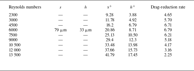
This study numerically analyses the drag-reduction performance of the fabricated ridge riblets, calculating their drag-reduction rates under different Reynolds numbers. Dimensionless parameters
 $s^{+}$
and
 $h^{+}$
, representing riblet geometry, are defined in (3.2). Table 3 summarises the results, revealing that ridge riblets achieved drag reduction across the range 2300 ≤ Re ≤ 13 500. The maximum reduction, 6.79 %, was observed at
 $s^{+}$
= 20.86,
 $h^{+}$
= 8.71 and Re = 6000
 \begin{equation} \eta =\frac{C_{\textit{smooth}}-C_{\textit{riblet}}}{C_{\textit{smooth}}}=\frac{\Delta pa-\Delta pa_{0}}{\Delta pa}\times 100\,\%. \end{equation}
Equation (3.3) is for calculating the drag coefficient, where
 $C_{\textit{smooth}}$
refers to the drag coefficient of the smooth surface, and
 $C_{\textit{riblet}}$
refers to the drag coefficient of the riblet surface. A positive drag-reduction rate indicates that the riblet surface effectively reduces drag, whereas a negative rate implies an increase in drag
 \begin{equation} C=\frac{\tau _{w}}{\frac{1}{2}\rho u^{2}}. \end{equation}
where
 $\tau _{w}$
is the wall shear stress,
 $u$
the mean velocity and
 $\rho$
is the density of water.
Drag-reduction rates of riblet structure at different Reynolds numbers.

Table 3. Long description
A table summarizing the drag-reduction rates of riblet structures at various Reynolds numbers. The table has six columns and nine rows, including the header row. The columns are labeled as follows: Reynolds numbers, s, h, s+, h+, and Drag-reduction rate. The row labels are the specific values for each parameter. The values in the table are as follows: Row 1: Reynolds numbers, 2300; s, 79 micrometers; h, 33 micrometers; s+, 9.28; h+, 3.88; Drag-reduction rate, 4.65. Row 2: Reynolds numbers, 3000; s, 79 micrometers; h, 33 micrometers; s+, 11.78; h+, 4.92; Drag-reduction rate, 5.70. Row 3: Reynolds numbers, 4500; s, 79 micrometers; h, 33 micrometers; s+, 16.2; h+, 6.79; Drag-reduction rate, 6.71. Row 4: Reynolds numbers, 6000; s, 79 micrometers; h, 33 micrometers; s+, 20.86; h+, 8.71; Drag-reduction rate, 6.79. Row 5: Reynolds numbers, 7500; s, 79 micrometers; h, 33 micrometers; s+, 25.13; h+, 10.50; Drag-reduction rate, 6.21. Row 6: Reynolds numbers, 9000; s, 79 micrometers; h, 33 micrometers; s+, 29.4; h+, 12.3; Drag-reduction rate, 5.18. Row 7: Reynolds numbers, 10500; s, 79 micrometers; h, 33 micrometers; s+, 33.48; h+, 13.98; Drag-reduction rate, 4.17. Row 8: Reynolds numbers, 12000; s, 79 micrometers; h, 33 micrometers; s+, 37.66; h+, 15.73; Drag-reduction rate, 3.16. Row 9: Reynolds numbers, 13500; s, 79 micrometers; h, 33 micrometers; s+, 41.79; h+, 17.45; Drag-reduction rate, 2.25. The table reveals that the drag-reduction rate varies with different Reynolds numbers and riblet geometries.
As shown in figure 15, in its comparison of ridge-type riblet drag-reduction performance, the computed drag-reduction rates of ridge riblets were compared with values for other riblet types simulated by Martin & Bhushan (Reference Martin and Bhushan2014). The performance of the ridge-type surface of riblets surpassed scalloped and sawtooth riblet surfaces but was inferior to blade riblet surfaces. However, due to the high cost and complex manufacturing process of the blade-shaped riblet structure, and considering the favourable drag-reduction performance of the ridge-type riblet structure, it is deemed a viable method for drag reduction.
Comparison of ridge-type riblet drag-reduction performance (Martin & Bhushan Reference Martin and Bhushan2014).

Figure 16 shows the streamwise velocity profiles of a smooth surface. These profiles correspond to the tip, middle and valley of the riblet structure. The velocity distribution covers the near-wall region with y + values from 0 to 20. At different characteristic locations, the velocity gradient decreases in the order of the smooth surface (approximately equal to the riblet tip), then the middle and finally the valley. This decrease results from the transverse velocity effect induced by the riblet tops. The riblet tops change the near-wall flow structure and slow the fluid motion, which reduces the overall flow velocity. In addition, the mean velocity profiles above the riblet valleys show an upward shift in the logarithmic region compared with those of the smooth plate. This shift is linked to the slower flow in the valleys and the increased thickness of the viscous sublayer.
Mean streamwise velocity profile.

Contours of shear stress for smooth/riblet structure.

Figure 17. Long description
Panel A: Two heat maps showing wall stress contours on smooth and riblet surfaces. The smooth surface heat map displays a variety of colors indicating different levels of wall stress, with a color scale ranging from blue (low stress) to red (high stress). The riblet surface heat map shows predominantly blue regions, indicating lower wall stress overall. A specific area on the riblet surface is highlighted with a dashed circle. Panel B: A heat map showing riblet surface shear stress contours. This heat map has a grid layout with vertical stripes of varying colors, indicating different levels of shear stress. The color scale ranges from blue (low stress) to red (high stress). The heat map shows a pattern of alternating high and low stress regions along the vertical direction.
Figure 17 illustrates the shear-stress contours for both riblet and smooth surfaces. On the upper wall (smooth surface), the shear-stress distribution features alternating regions of high and low shear, creating a distinct pattern. In contrast, the wall shear stress on the lower wall (riblet surface) is more uniform and generally lower. Further analysis indicates that the riblet surface predominantly experiences low shear, with a localised high shear region concentrated at the riblet top. This localised high shear is attributed to a direct vortex sweep at the tip of the riblet, significantly influenced by the underlying vortex structure, which induces more complex and intense flow characteristics. Overall, compared with the smooth surface, the riblet configuration effectively moderates both the extent and intensity of high shear-stress regions, thereby reducing flow resistance.
Figure 18 compares shear-stress contours on a riblet surface with those on a smooth surface. The smooth surface shows only minor fluctuations in shear stress. In contrast, the riblet surface exhibits variations that follow its geometry. The riblet tips have the highest shear stress. This stress decreases along the sidewalls and is lowest at the base. Even though the peaks experience maximum stress, their small area results in a lower area-weighted average shear stress than that of the smooth surface. This confirms that the riblet design effectively reduces frictional drag.
Wall shear-stress contours for smooth and riblet surfaces.

Figure 19 illustrates the velocity streak structures observed above both the smooth and riblet surfaces. In figure 19(a), the smooth surface exhibits chaotic, high-speed velocity streaks, which suggest the occurrence of frequent turbulent bursts. By contrast, the riblet surface displays continuous, orderly and slower streaks, indicative of a reduced frequency of turbulent bursts. Figure 19(b) reveals that the distributions of velocity streaks on the smooth and riblet surfaces are nearly identical. Comparisons between figures 19(a) and 19(b) suggest that the presence of riblets causes high-speed fluid originally located at a given position to be displaced upward, leading to slower, laminar flow within the riblet cavities. This phenomenon is attributable to the upward displacement of the viscous sublayer and the formation of secondary vortices at the riblet tips, which elevate the streamwise vortices away from the wall and suppress the development of turbulence.
Velocity streak contour plots above smooth and riblet surfaces.

Figure 20 illustrates the average vorticity contours in turbulent channel flow. The smooth surface exhibits a greater number of regions with elevated vorticity, while the riblet surface demonstrates lower vorticity magnitudes, with high-vorticity zones predominantly concentrated near the riblet tips.
Average vorticity contour plots for upper and lower surfaces.

Streamwise vortices in turbulent boundary layer structures are often observed within low-speed streaks and manifest as counter-rotating pairs. These vortices transport high-speed fluid downward toward the surface while lifting low-speed fluid upward, thereby enhancing turbulence generation. Figure 21 presents instantaneous vorticity contours on cross-sectional planes above both the upper and lower surfaces. As shown in figure 21(a), the majority of the vortices remain proximate to the upper surface, exposing the smooth surface primarily to high-speed turbulence and thereby increasing wall friction. In contrast, figure 21(b) demonstrates that most vortices concentrate at the riblet peaks without directly interacting with the riblet surface. The counter-rotating vortices engage with the riblet peaks to generate secondary vortices at the riblet tips, which subsequently weaken the primary vortices. These attenuated vortices are then lifted away from the surface, reducing the formation of irregular classical streamwise vortices, decreasing near-wall turbulence bursts and ultimately diminishing energy dissipation.
Instantaneous vorticity contours of the upper and lower wall flow fields.

Figure 22(a) compares the vortex structures on riblet surfaces with those on smooth surfaces. On the smooth surfaces, the vortex structures are continuous and large, which results in more intense turbulent bursts and frequent turbulent activities, thereby increasing energy loss. In contrast, the vortex structures on riblet surfaces are sparse and discontinuous, which suppresses their spanwise motion and reduces energy dissipation, ultimately lowering the surface shear stress. Figure 22(b) presents a side view that demonstrates how riblets promote the displacement of vortex structures away from the wall, thereby confirming that riblets can induce streamwise vortices to recede from the wall surface.
Distribution map of vortex cores.

A comparative analysis of velocity vector fields above the riblet surface is conducted at three Reynolds numbers: figure 23(a) for Re = 5700 (
 $s^{+}$
= 20), figure 23(b) for Re = 9700 (
 $s^{+}$
= 30) and figure 23(c) Re = 16 000 (
 $s^{+}$
= 45). At
 $s^{+}$
= 20, the vortex diameter is measured at
 $d^{+}\approx$
40, exceeding the riblet spacing. As a result, the vortices are confined near the riblet peaks, leaving most of the riblet surface in a predominantly low-speed, laminar state, which enhances drag reduction. When
 $s^{+}$
is increased to 30, the vortex diameter expands to
 $d^{+}\approx$
45, continuing to exceed the riblet spacing and thus maintaining a largely laminar environment within the riblets.
Velocity vector diagrams above the riblet surface.

However, as
 $s^{+}$
is further elevated to 45, the vortex diameter decreases to
 $d^{+}\approx$
35, falling below the riblet spacing. This reduction permits the vortices to penetrate into the riblet valleys, increasing the exposure of the riblet surface to lateral sweeping. Consequently, skin friction rises, which offsets the drag-reducing benefits.
In summary, ridge riblets decelerate internal flow and thicken the boundary layer, thereby mitigating turbulent bursts near the wall. Their interaction with streamwise vortices generates secondary vortices that elevate and attenuate the primary vortices, ultimately resulting in drag reduction.
4. The test of riblet drag-reduction rate
4.1. Experimental set-up and process
Experiments are performed in a water -circulating tunnel. See figure 24 for details. A contraction section is installed before the test section to boost fluid speed and stabilise the incoming flow. A water pump installed at the base facilitates fluid recirculation, while the integrated motor regulates water velocity. The test section, made of acrylic for easy observation, measures 10 cm wide, 10 cm high and 60 cm long. Its top and bottom surfaces are removable to accommodate various surfaces for turbulence testing. Rubber rings around the upper and lower covers guarantee the test section’s watertight integrity and secure experimental data.
Physical pictures of the circulating water tunnel.

In this experiment, as illustrated in figure 25, a rectangular groove is machined into the upper plate to subsequently accommodate the riblet-structured surface. To avoid wall -effect impacts, the groove is located in the middle of the plate, with a size of 300 mm in length, 50 mm in width and 3 mm in depth. For turbulent flow development, the channel length should be over 25 times the hydraulic diameter to reach a fully developed turbulent state. However, the test section here does not meet this requirement. So, a semicircular trip wire (1 mm radius) is installed at the front of the upper plate to rapidly trip the flow and establish a fully developed turbulent state.
Diagram of the upper cover plate test section.

Before starting the experiment, we drilled two circular holes on the smooth surface of the test section and connected them to the differential pressure transmitter with sealed tubes. The upstream hole was linked to the positive end, while the downstream hole was connected to the negative end. At a flow velocity of 0 m s−1 and system stability, we recorded the initial pressure difference
 ${\varDelta}_{pa0}$
. For flow velocities ranging from 2 to 6 m s−1, we measured the differential pressure
 ${\varDelta}_{pa}$
once the fluid stabilised and used (3.4) to calculate the drag-reduction rate
 \begin{equation} \eta =\frac{\Delta pa-\Delta pa_{0}}{\Delta pa}\times 100\,\%. \end{equation}
4.2. Results and discussion
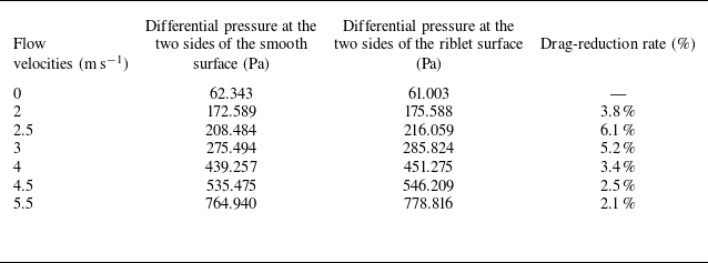
The pressure differences at both ends of the riblet-structured and smooth plate test sections are measured under various flow rates. Then, the drag-reduction rates for different flow rates are calculated via (3.3). The results are shown in table 4.
Drag-reduction rates of riblet surface at different flow velocities.

Table 4. Long description
A table with three columns and six rows, including a header row. The columns are labeled Flow velocities (m s inverse), Differential pressure at the two sides of the smooth surface (Pa), Differential pressure at the two sides of the riblet surface (Pa), and Drag-reduction rate (percent). The rows present data for flow velocities ranging from 0 to 5.5 m s inverse. Each row lists the corresponding differential pressures and drag-reduction rates. Notable trends include varying drag-reduction rates across different flow velocities, with the highest drag-reduction rate of 6.1 percent at a flow velocity of 2.5 m s inverse and the lowest drag-reduction rate of 2.1 percent at a flow velocity of 5.5 m s inverse.
Figure 26 illustrates the variation in the drag-reduction rate on riblet surfaces as a function of velocity. The experimental results and numerical simulations showed a similar trend. At a velocity of 2.5 m s−1, maximum drag reductions of 6.79 % (simulation) and 6.1 % (experiment) were observed; beyond this point, the drag reduction gradually decreased as velocity increased. However, due to experimental limitations, the fluid flow did not fully become turbulent. Also, numerical simulations ignored structural deformations, which gave higher drag-reduction rates than the experiments.
Variation of the drag-reduction rate of riblet structures with flow velocity.

5. Conclusion
This paper presents an effective method for fabricating ridge-type riblet drag-reduction surfaces. A comprehensive series of numerical and experimental investigations was conducted to elucidate the drag-reduction mechanisms. The findings indicate that:
-
(i) The buckling method is different from conventional techniques like photolithography and high-precision milling. It employs a hard film on a soft substrate to fabricate drag-reducing surfaces without the necessity for high-precision equipment. It also avoids complex processing procedures. Consequently, this approach reduces fabrication costs while streamlining and accelerating the overall process.
-
(ii) When unstretched, the hard film/soft substrate forms wrinkled stripes under slight compression, then develops a doubled periodic pattern at higher strains. Pre-stretching initially creates sinusoidal wrinkles, which subsequently bifurcate into periodic ridges with a higher aspect ratio. A pre-stretch ratio of 0.43 is key for stable, optimally proportioned riblets. Also, ridge amplitude increases with UV exposure while wavelength decreases, allowing precise dimension control.
-
(iii) The simulation results demonstrate that, under identical conditions, ridge riblets achieve more effective drag reduction than both sawtooth and scalloped riblets. Furthermore, the trends observed in both simulations and experiments are consistent. As flow velocity increases, drag reduction initially improves and then declines. Maximum drag-reduction values of 6.79 % (simulation) and 6.1 % (experiment) were recorded at a velocity of 2.5 m s−1.
-
(iv) Simulation results show that the flow inside the ridge riblets is significantly slower. The viscous sublayer within the boundary layer increases in thickness. The ridge riblets weaken the intensity and frequency of near -wall turbulent bursts. Also, the interaction between streamwise vortices and the ridge tops creates secondary vortices. These secondary vortices move the primary vortices away from the wall and reduce their intensity. This cuts down turbulence and drag.
The current research focuses on the verification of process feasibility and the control of microstructure uniformity. Subsequently, efforts will be made to assess marine environmental performance, develop composite forming processes for rigid substrates and tackle key technologies for square-metre-scale manufacturing, thereby promoting the transition of the technology from laboratory concept validation to engineering application.
Funding
The present work is supported by the National Science Foundation of China under Grant No. 12472127.
Declaration of interests
The authors report no conflict of interest.



 γ=013,0.20,0.33,0.43,0.48,0.50