


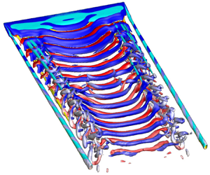





1. Introduction
The low-speed flow past a wing is majorly governed by its geometry, orientation to the incoming flow and the Reynolds number ( $Re = Uc/v$, where U is the free-stream speed, c is the chord length of the wing and v is the kinematic viscosity of the fluid). Some of the parameters that describe the geometry of the wing are its airfoil section, planform, aspect ratio, sweep and twist across the span (Prandtl Reference Prandtl1918, Reference Prandtl1921; Mueller & DeLaurier Reference Mueller and DeLaurier2003) The flow spills and curls around the wing tips due to the pressure difference between the lower and upper surfaces to form a pair of streamwise oriented ‘wing-tip’ vortices. The downwash generated by each wing-tip vortex reduces the effective angle of attack of the airfoil section at each spanwise location of the wing, with respect to the free-stream velocity, by
 $\alpha _i$, known as the induced angle of attack. According to the lifting line theory (Prandtl Reference Prandtl1918, Reference Prandtl1921; Bertin Reference Bertin2002; Anderson Reference Anderson2017), the induced angle of attack for a wing with elliptic planform and no twist is constant across its span. On the other hand, it is maximum at the wing tip for a wing with rectangular planform and decreases monotonically towards the wing root. Micro air vehicles (MAVs) typically operate at low
 $Re$ (
 $10^4\unicode{x2013}10^5$) owing to their small size and low speed (McMasters & Henderson Reference McMasters and Henderson1979; Carmichael Reference Carmichael1981; Burns & Mueller Reference Burns and Mueller1982; Mueller & Jansen Reference Mueller and Jansen1982; Mueller & DeLaurier Reference Mueller and DeLaurier2003; Shkarayev et al. Reference Shkarayev, Ifju, Kellogg and Mueller2007). The boundary layer is laminar at low
 $Re$ (
 ${<}3\times 10^4$ approximately) and does not reattach after separation (Zhang et al. Reference Zhang, Hayostek, Amitay, Burtsev, Theofilis and Taira2020a,Reference Zhang, Hayostek, Amitay, He, Theofilis and Tairab; Ribeiro et al. Reference Ribeiro, Neal, Burtsev, Amitay, Theofilis and Taira2023; Ribeiro & Taira Reference Ribeiro and Taira2024). A laminar separation bubble forms at larger
 $Re$. The wings that are designed for relatively high
 $Re$ exhibit poor aerodynamic performance at low
 $Re$. Therefore, studies at low Re are important for the design of air vehicles that operate at low
 $Re$. The present study investigates the effect of wing twist on the aerodynamic performance of an air vehicle at low
 $Re$. We believe that the findings of the present work can be useful while designing a fixed wing MAV and utilize the geometric twist of the wing as a design parameter. The present findings might be also be useful for analysing flows in sailplanes, windmills and propellers.
The wing-tip vortex has a significant effect on vortex shedding at low  $Re$ (Pandi & Mittal Reference Pandi and Mittal2023). Vortex shedding is completely suppressed all across the span for low aspect ratio wings, while the suppression is local to the wing-tip region for wings with relatively large aspect ratio (Mittal & Tezduyar Reference Mittal and Tezduyar1995; Taira & Colonius Reference Taira and Colonius2009; Zhang et al. Reference Zhang, Hayostek, Amitay, He, Theofilis and Taira2020b; Pandi & Mittal Reference Pandi and Mittal2023). Taira & Colonius (Reference Taira and Colonius2009) showed that, compared with a flat plate with rectangular planform, non-rectangular planforms are associated with increased delay in flow separation and lower unsteadiness. Swanson & Isaac (Reference Swanson and Isaac2010) concluded the same for wings with a cambered airfoil section. Zhang et al. (Reference Zhang, Hayostek, Amitay, Burtsev, Theofilis and Taira2020a) and Zhang & Taira (Reference Zhang and Taira2022) showed that vortex shedding weakens with increasing sweep angle of the wing planform. They demonstrated that the flow, even for a large aspect ratio wing, is devoid of vortex shedding if the sweep angle is large enough. All of these studies were carried out for
 $Re$ in the range 300–1000, based on the free-stream speed, kinematic viscosity of the flow and mean aerodynamic chord of the wing (
 $\bar {c}$). Several of these studies were carried out for half of the span of the wing. For such a geometry, one can define the semi-aspect ratio as
 $sAR=b/{2\bar {c}}$ (Zhang et al. Reference Zhang, Hayostek, Amitay, He, Theofilis and Taira2020b; Pandi & Mittal Reference Pandi and Mittal2023), where
 $b$ is the span length.
An interesting feature of the flow past a finite wing at low  $Re$ is the formation of cells across its wing span. Zhang et al. (Reference Zhang, Hayostek, Amitay, He, Theofilis and Taira2020b) studied the effect of
 $sAR$ on the
 $Re=400$ flow past a wing with NACA 0015 section placed at
 $\alpha > 12^\circ$. Vortex shedding with two cells along the span was found for
 $sAR \geqslant 4$. Pandi & Mittal (Reference Pandi and Mittal2023) reported two-cell shedding for
 $sAR \geqslant 3$ at a relatively larger
 $Re$ (
 $=1000$) and
 $\alpha =14^\circ$ for a wing with NACA 0012 section. The frequency of vortex shedding is invariant within a cell and changes from one cell to another. The vortices with different shedding frequency establish a connection, termed as dislocation, across cell boundaries to preserve the net circulation (Batchelor Reference Batchelor1964). Dislocations have been studied in fair detail in bluff body flows (Gaster Reference Gaster1971; Gerich & Eckelmann Reference Gerich and Eckelmann1982; Eisenlohr & Eckelmann Reference Eisenlohr and Eckelmann1989; Williamson Reference Williamson1989; Konig, Eisenlohr & Eckelmann Reference Konig, Eisenlohr and Eckelmann1990; Albarède & Monkewitz Reference Albarède and Monkewitz1992; Leweke et al. Reference Leweke, Provansal, Miller and Williamson1997; Behara & Mittal Reference Behara and Mittal2010; Tian et al. Reference Tian, Jiang, Pettersen and Andersson2017; Mittal, Pandi & Hore Reference Mittal, Pandi and Hore2021). Fork-type (
 $D_f$) and mixed-type (
 $D_{f-fc}$) dislocations, observed in bluff body flows, are also found in flow past wings (Pandi & Mittal Reference Pandi and Mittal2023). An additional kind, the reverse fork-type (
 $D_{rf}$), formed as a result of splitting and reconnection of vortices, was reported by Pandi & Mittal (Reference Pandi and Mittal2023). In the present work, we investigate the effect of
 $Re$ on the cellular shedding, vortex shedding frequency, vortex dislocations and force coefficients for
 $100 \leqslant Re \leqslant 2500$. Studies in the past have explored the effect of planform and sweep angle on vortex structures and cellular shedding. Geometric twist is often used in wings to tune their stall characteristics. The effect of twist on the flow at low
 $Re$ has, however, not been studied in the past. In the present work, we explore the effect of geometric twist of the wing on cellular shedding and the associated force coefficients.
Pandi & Mittal (Reference Pandi and Mittal2023) compared the aerodynamic force coefficients obtained from direct numerical simulations with the predictions from lifting line theory (LLT) (Prandtl Reference Prandtl1918, Reference Prandtl1921). In contrast to the prediction from LLT, the drag coefficient increases with an increase in the aspect ratio of the wing. The spillage of flow at the wing tip reduces the peak suction on the upper surface of the wing, resulting in a lower adverse pressure gradient compared with that for the corresponding airfoil. Therefore, the flow separation is suppressed for a very low aspect ratio wing and delayed for wings with moderate  $sAR$. As a result, at low
 $Re$, the increased pressure drag with increase in
 $sAR$ causes the overall drag coefficient for a finite wing to increase. The lift coefficient, however, increases with increase in
 $sAR$, as predicted by LLT. Therefore, irrespective of the range of
 $Re$, the aerodynamic performance of a finite wing, owing to the wing-tip vortices, is lower than that of the corresponding airfoil section (Prandtl Reference Prandtl1918, Reference Prandtl1921; Zhang et al. Reference Zhang, Hayostek, Amitay, Burtsev, Theofilis and Taira2020a,Reference Zhang, Hayostek, Amitay, He, Theofilis and Tairab; Pandi & Mittal Reference Pandi and Mittal2023). The sweep angle of the finite wing also affects the force coefficients (Zhang et al. Reference Zhang, Hayostek, Amitay, Burtsev, Theofilis and Taira2020a; Zhang & Taira Reference Zhang and Taira2022). At lower angles of attack, the force coefficients of backward swept wing are larger than those for a forward swept wing while the trend reverses at higher angles of attack. The spanwise lift distribution is significantly affected by the sweep. The sectional lift coefficient of a straight edged rectangular wing, as predicted by the LLT, is maximum at the wing root and decreases monotonically towards the wing tip (Prandtl Reference Prandtl1918, Reference Prandtl1921). Such a variation is observed at large
 $Re$ as well, as confirmed by the experimental investigation by Bastedo & Mueller (Reference Bastedo and Mueller1985) at
 $Re=2\times 10^5$. At low
 $Re$, however, the variation of the sectional lift coefficient is non-monotonic across the span (Zhang et al. Reference Zhang, Hayostek, Amitay, He, Theofilis and Taira2020b; Pandi & Mittal Reference Pandi and Mittal2023). This is due to the formation of streamwise vortices at several spanwise locations, in addition to the wing-tip vortices. In case of forward sweep, the local sectional force coefficients increase from wing root to wing tip whereas the variation is the opposite for a backward swept wing (Zhang et al. Reference Zhang, Hayostek, Amitay, Burtsev, Theofilis and Taira2020a; Zhang & Taira Reference Zhang and Taira2022).
A parameter that affects the aerodynamic performance of a finite wing is its geometric twist (Bertin Reference Bertin2002; Anderson Reference Anderson2017) that results in a varying angle of attack of the airfoil section across the wing span. Let  $\alpha _r$ and
 $\alpha _t$ denote the angle of attack of the airfoil section at the wing root and wing tip, respectively. The geometric twist is defined as
 $\delta =\alpha _t-\alpha _r$. The case
 $\delta <0^\circ$ is referred to as wash-out, wherein the angle of attack at the wing tip is smaller than that at the wing root, while
 $\delta >0^\circ$ (
 $\alpha _t > \alpha _r$) is identified as wash-in. Phillips (Reference Phillips2004) utilized the LLT to predict the wash-out angle that results in the minimum induced drag coefficient for rectangular and tapered wings operating at a specific lift coefficient. It was found that, for an optimal twist, the aerodynamic performance of rectangular and tapered wings is almost the same as that of an elliptic wing with no twist. Phillips & Alley (Reference Phillips and Alley2007) and Alley, Phillips & Spall (Reference Alley, Phillips and Spall2007) reported that wash-out and sweep decrease the aerodynamic performance of wings with rectangular and tapered planform. Taylor, Newman & Barnwell (Reference Taylor, Newman and Barnwell1997) utilized an optimization strategy and the Euler equations to determine the twist for optimal aerodynamic performance of a B747-200 wing at
 $\alpha =2.73^\circ$. It was found that, compared with the base wing, the one with negative twist has larger suction on the upper surface of the wing, leading to maximization of the aerodynamic efficiency. Kelayeh & Djavareshkian (Reference Kelayeh and Djavareshkian2021) conducted numerical investigation on a tailless aircraft with a NACA 66-009 section at
 $Re=0.69\times 10^6$ for
 $-6^\circ \leqslant \delta \leqslant 0^\circ$ and
 $-5^\circ \leqslant \alpha \leqslant 20^\circ$. The twist varies linearly across the wing span. It was found that, at low
 $\alpha$, the twist decreases the lift coefficient whereas, at larger
 $\alpha$, the lift coefficients of untwisted and twisted wings are indistinguishable. Kelayeh & Djavareshkian (Reference Kelayeh and Djavareshkian2024) extended their earlier study to include positive wing twist (
 $-12^\circ \leqslant \delta \leqslant 12^\circ$) and implemented cubic twist variation across the wing span. It was found that positive twist results in poor aerodynamic characteristics at large angles of attack. It was also shown that unequal twist on both sides of the wing can be utilized to suppress the yawing moment at large angles of attack. Kaygan & Ulusoy (Reference Kaygan and Ulusoy2018) utilized a tool, developed by Drela & Youngrend (Reference Drela and Youngrend2012), based on the vortex-lattice method to explore the aerodynamic characteristics of a swept wing with a NACA 2415 section for
 $-4^\circ \leqslant \alpha \leqslant 20^\circ$ and
 $-8^\circ \leqslant \delta \leqslant 8^\circ$. The aerodynamic efficiency of the twisted wing was found to be
 $2\,\%$ larger than the untwisted wing. However, the twist decreases the pitching moment and reduces the trim angle of attack. Similar detailed analysis to evaluate the effect of twist of a wing on its aerodynamic performance is not available at low
 $Re$ to the best of the knowledge of the authors. In the present work, we investigate the effect of twist on the vortex shedding and the time-averaged aerodynamic coefficients as well as their root mean square (r.m.s.) at low
 $Re$. It is useful, at this point, to understand one major difference between high vs low
 $Re$ flow past wings. At high
 $Re$ the wings exhibit the phenomenon of stall, wherein the lift decreases very rapidly with an increase in the angle of attack, beyond a certain critical
 $\alpha$ (Gregory & O'reilly Reference Gregory and O'reilly1970; Winkelmann et al. Reference Winkelmann, Barlow, Saini, Anderson and Jones1980; Sheldahl & Klimas Reference Sheldahl and Klimas1981; Ladson, Hill & Johnson Reference Ladson, Hill and Johnson1987; Bertin Reference Bertin2002; Alam et al. Reference Alam, Zhou, Yang, Guo and Mi2010; Anderson Reference Anderson2017). Ailerons are typically located near wing tips. A wash-out configuration (
 $\delta <0^\circ$) is often utilized to avoid stall of flow near the wing tips so that the ailerons remain effective in controlling the aerial vehicle even at high
 $\alpha$. Unlike at high
 $Re$, the flow at low
 $Re$ is devoid of an abrupt stall (Srinath & Mittal Reference Srinath and Mittal2009; Taira & Colonius Reference Taira and Colonius2009; Zhang et al. Reference Zhang, Hayostek, Amitay, Burtsev, Theofilis and Taira2020a,Reference Zhang, Hayostek, Amitay, He, Theofilis and Tairab; Maji, Pandi & Mittal Reference Maji, Pandi and Mittal2024). Therefore, the twist can be utilized to improve the aerodynamic performance of the wing at low
 $Re$ without being concerned with the stall.
Most of the studies discussed above have investigated the three-dimensional (3-D) vortex structures, cellular shedding, dislocations and force coefficients of flow past stationary wings. A few studies have also been carried out on non-stationary wings (Visbal, Yilmaz & Rockwell Reference Visbal, Yilmaz and Rockwell2013; Rockwood et al. Reference Rockwood, Medina, Garmann and Visbal2019; Visbal & Garmann Reference Visbal and Garmann2019; Son et al. Reference Son, Gao, Gursul, Cantwell, Wang and Sherwin2022). Son et al. (Reference Son, Gao, Gursul, Cantwell, Wang and Sherwin2022) prescribed a plunging motion to a  $sAR=5$ wing with a NACA 0012 section at
 $Re=10\,000$. It was found that the leading edge vortex convects and forms a helical vortex structure. Visbal et al. (Reference Visbal, Yilmaz and Rockwell2013) reported an arch vortex on a plunging
 $sAR=1$ wing with flat plate at
 $Re=10\,000$. A similar vortex structure was also found on a stationary wing in the study carried out by Pandi & Mittal (Reference Pandi and Mittal2023) due to the interaction of the wing-tip vortex and vortex shedding. It appears that the flow structures in stationary and oscillating wings have some commonality, although they appear for different parameter range. Unmanned air vehicles and MAVs are of interest owing to their utility in surveillance, communications and rescue operations. They are associated with low Reynolds number flight due to their relatively small size and low speed (Mueller & DeLaurier Reference Mueller and DeLaurier2003; Shkarayev et al. Reference Shkarayev, Ifju, Kellogg and Mueller2007).
Despite a fairly large number of efforts in the past to understand the effect of planform and sweep, to the best of our knowledge, there has been no study at low  $Re$ that addresses the effect of geometric twist of a wing. In the present study, we first investigate the flow and aerodynamic coefficients of an untwisted wing for
 $100 \leqslant Re \leqslant 2500$. The effect of geometric twist on the overall and spanwise distribution of the sectional aerodynamic coefficients as well as their fluctuations at low
 $Re$ (
 $=1000$) are studied. The effect of geometric twist on the strength of the wing-tip vortex is also explored. We address the following questions. (i) What is the effect of
 $Re$ on the flow and aerodynamic coefficients for an untwisted wing? (ii) How do the vortex shedding and dislocation frequency vary with
 $Re$ on an untwisted wing? (iii) What is the effect of twist on the cellular shedding and the associated vortex dislocations? Is there a connection between the cellular vortex shedding frequency of the twisted and untwisted wings? (iv) What is the effect of twist on the spanwise distribution of the sectional force coefficients and overall aerodynamic performance in terms of the time-averaged and r.m.s. force coefficients? (v) What is the effect of wing semi-aspect ratio on the cellular structure? (vi) How does the strength of the wing-tip vortex vary with twist and how does it compare with that for the untwisted wing? A stabilized finite element formulation based on streamline-upwind/Petrov–Galerkin and pressure-stabilizing/Petrov–Galerkin stabilizing techniques (Tezduyar et al. Reference Tezduyar, Mittal, Ray and Shih1992b) is utilized to solve the Navier–Stokes equations for an incompressible flow. The details of the formulation can be found in our earlier work (Mittal Reference Mittal2000, Reference Mittal2001; Behara & Mittal Reference Behara and Mittal2009). The formulation is implemented on a distributed memory parallel system. Message passing interface libraries have been used for interprocessor communication. For more details regarding the parallel implementation, the interested reader may refer to the work by Behara & Mittal (Reference Behara and Mittal2009). Pandi & Mittal (Reference Pandi and Mittal2023) used only one half of the span in their computations. They assessed the adequacy of such computations by carrying out a few simulations for the full span of the wing. These simulations reveal that the flow retains its symmetry about the mid-span and is identical to that obtained with computations for half the span. Several studies in the past have also simulated the half-span of the wing (Zhang et al. Reference Zhang, Hayostek, Amitay, Burtsev, Theofilis and Taira2020a,Reference Zhang, Hayostek, Amitay, He, Theofilis and Tairab; Zhang & Taira Reference Zhang and Taira2022). We study the adequacy of the half-span of the wing for the parameter space explored in this work. A few computations are carried out with the full span of the wing without and with twist. It is found that the flow retains its symmetry about the mid-span and the flow for each half-span of the full span is identical to that obtained with half-span computations. The present study, therefore, employs only one half of the wing span.
2. Problem set-up, computational details and finite element mesh
We study the flow past a rectangular wing of span  $b$ and chord length
 $c$, with a NACA 0012 section wing placed in a uniform flow. Figure 1(a) shows the schematic of the problem set-up. Also shown is the computational domain and flow conditions applied at its boundaries. The set-up is similar to the one used in our earlier study (Pandi & Mittal Reference Pandi and Mittal2023). To save computational resources, one half of the span, with symmetry flow conditions applied at the root section (face ADHE in figure 1a), is considered. The semi-aspect ratio of the wing (
 $sAR=b/2\bar {c}$) is
 $5$. The incoming flow is aligned with the
 $x$-axis. The Reynolds number based on the chord length is
 $1000$. Computations are also carried out for an end-to-end wing (EEW) that spans the entire lateral extent of the computational domain. We consider a span length of
 $5c$. Pandi & Mittal (Reference Pandi and Mittal2019), for flow past an Eppler 61 airfoil, oriented at
 $\alpha =10^\circ$ to the free-stream, showed that a span of
 $1c$ is sufficient to obtain results that are independent of span length. We investigate the effect of span for the NACA 0012 section at two representative angles of attack
 $14^\circ$ and
 $20^\circ$. It is found that the flows with span length
 $L_z=1c$ and
 $5c$ are in excellent agreement. The details are presented in Appendix A. Figures 1(b) and 1(c) show schematics of the wing with wash-in and wash-out considered in this study. We refer to the angle of attack of the root and wing-tip sections, with respect to the direction of incoming flow, as
 $\alpha _r$ and
 $\alpha _t$, respectively, and characterize the twist by
 $\delta = \alpha _t -\alpha _r$. The geometric angle of attack varies linearly across the span between the root and wing tip. The centre of rotation for each local airfoil section is its mid-chord point. Results are presented in this work for
 $\alpha _r=8^\circ$ and
 $14^\circ$, while
 $\alpha _t$ is varied to study the effect of wing twist (
 $\delta$). In the schematics shown in figures 1(b) and 1(c), the angle of attack at wing root is
 $\alpha _r=14^\circ$, and the twist is
 $\delta =6^\circ$ and
 $-6^\circ$, respectively. The local geometric angle of attack at the wing tip for the two cases is
 $\alpha _t=20^\circ$ and
 $8^\circ$, respectively. We present results for various wing twists in the range
 $-6^\circ \leqslant \delta \leqslant 6^\circ$. We refer to
 $|\delta | > 4^\circ$ as high twist while the lower angles are referred to as low to moderate twist.
Flow past finite wing: (a) schematic of problem set-up (not to scale). Also shown are the boundary conditions. Schematics of a wing with twist corresponding to wash-in and wash-out are shown in (b,c), respectively. The angles of attack at wing root ( $\alpha _r$), wing tip (
 $\alpha _t$) and quarter span (
 $\alpha _{b/4}$) are highlighted in these images. The twist angles (
 $\delta = \alpha _t - \alpha _r$) in (b,c) are
 $6^\circ$ (wash-in) and
 $-6^\circ$ (wash-out), respectively.

First, a finite element mesh for an untwisted wing with  $\alpha =14^\circ$ is generated by stacking several copies, of a two-dimensional mesh around an airfoil, along the span. More details can be found in our earlier work (Pandi & Mittal Reference Pandi and Mittal2023). The two-dimensional (2-D) mesh consists of 43 474 nodes and 86 602 triangular elements. The surface of the airfoil is discretized via
 $250$ nodes. We refer to this mesh as
 $M_{2D}$. Copies of the 2-D mesh are uniformly spaced along the span for the EEW, but are more clustered near the wing tip for the finite wing to adequately resolve the wing-tip vortex and boundary layer. The 3-D mesh for the finite wing, beyond the extent of the span of the wing, is generated by stacking copies of a modified 2-D mesh (
 $M_{2Dout}$) that has additional nodes and elements to fill the space occupied by the airfoil section. A mesh moving scheme (Tezduyar et al. Reference Tezduyar, Behr, Mittal and Johnson1992a) is utilized to accommodate the twist in the wing by relocating the nodes of the mesh at each spanwise station for the modified angle of attack of the airfoil. This scheme has been used in our earlier studies as well (Srinath & Mittal Reference Srinath and Mittal2007, Reference Srinath and Mittal2009, Reference Srinath and Mittal2010). The angle of attack considered is
 $0^\circ \leqslant \alpha \leqslant 20^\circ$. A stabilized finite element method with linear interpolation for velocity and pressure is used to solve the incompressible flow (Tezduyar et al. Reference Tezduyar, Mittal, Ray and Shih1992b). This formulation has been successfully used in the past to solve a variety of flow problems (Chopra & Mittal Reference Chopra and Mittal2019; Pandi & Mittal Reference Pandi and Mittal2019, Reference Pandi and Mittal2023; Mittal et al. Reference Mittal, Pandi and Hore2021; Chopra & Mittal Reference Chopra and Mittal2022). The time integration of the governing flow equations is carried out using a time step size
 $\Delta t = 0.002$.
The numerical results reported in the past studies, for the NACA0012 airfoil at this  $Re$, are for 2-D computations. We compare our results for the aerodynamic coefficients, computed using the mesh
 $M_{2D}$, with those for
 $(\alpha, Re)=(15^\circ, 800)$, (
 $15^\circ, 1000$) and (
 $20^\circ, 1000$) (see table 1). The results from the present 2-D computations lie in the range of results reported from past studies. The value of force coefficients obtained by Gao et al. (Reference Gao, Cantwell, Son and Sherwin2023) are for
 $Re=800$. Also shown in the table are the results from the present study with 3-D computations for the EEW. The mesh for the EEW consists of 160 copies of mesh
 $M_{2D}$ stacked uniformly across a span of
 $5c$. In the 3-D computations, the airfoil spans the entire computational domain, making it a nominally 2-D wing. A similar set-up has been employed in our earlier studies on flow past airfoils (Savaliya, Kumar & Mittal Reference Savaliya, Kumar and Mittal2010; Pandi & Mittal Reference Pandi and Mittal2019, Reference Pandi and Mittal2023; Maji et al. Reference Maji, Pandi and Mittal2024). We note that, even for an airfoil, compared with the 3-D computations, the 2-D computations overpredict lift and drag, reflecting the need to account for the three-dimensionality of the flow for an accurate prediction of the force coefficient. The difference in the force coefficients between the 3-D and 2-D computations is relatively small for
 $Re=800$ when compared with that for
 $Re=1000$. The three-dimensionality becomes strong with an increase in
 $Re$. The effect of three-dimensionality on the force coefficients has also been studied in the past for a circular cylinder (Mittal & Balachandar Reference Mittal and Balachandar1995) and airfoil (Zhang & Samtaney Reference Zhang and Samtaney2014, Reference Zhang and Samtaney2016; Pandi & Mittal Reference Pandi and Mittal2019; Gao et al. Reference Gao, Cantwell, Son and Sherwin2023; Maji et al. Reference Maji, Pandi and Mittal2024).
Flow past an NACA 0012 airfoil at  $Re = 1000$ in two dimensions: time-averaged lift and drag coefficients from present computations and the ones from the literature at
 $\alpha =15^\circ$ and
 $20^\circ$. The mesh
 $M_{2D}$ used in present study has 43 474 nodes and 86 602 elements. Also reported are the force coefficients obtained with 3-D computations for the EEW. The values obtained for
 $Re=800$ are compared with those from Gao et al. (Reference Gao, Cantwell, Son and Sherwin2023).

To establish the adequacy of the mesh used in the present work, we carry out a convergence study for the untwisted  $sAR=5$ wing at
 $\alpha =20^\circ$ and
 $Re=1000$ with two meshes. Both are generated using the same 2-D mesh, but have varying spanwise resolution. Mesh
 $M_{3D}^1$ uses
 $186$ while mesh
 $M_{3D}^2$ uses
 $263$ copies of the 2-D mesh stacked along the span of the wing. Table 2 lists the details of the meshes along with the time-averaged and r.m.s. force coefficients obtained with them. The results from two meshes are in very good agreement. This confirms the adequacy of mesh
 $M_{3D}^1$ to resolve the spatial structures for the
 $Re$ considered in this study. Therefore, all the computations in the present work are carried out with mesh
 $M_{3D}^1$. A similar mesh was utilized in our earlier study (Pandi & Mittal Reference Pandi and Mittal2023), which provides more details on the mesh, its validation and comparison with earlier studies.
Flow past an untwisted  $sAR=5$ wing at
 $\alpha = 20^\circ$ and
 $Re = 1000$: aerodynamic coefficients obtained using two finite element meshes. Here,
 $N_z$ denotes the number of copies of a 2-D mesh stacked along the lateral extent of the computational domain. Of these,
 $N_{wing}$ is the number of sections that lie on the wing.

The adequacy of half a span is assessed by carrying out computations for a few cases of untwisted and twisted wings for a full span. These results are reported in Appendix B. It is found that the half-span results are identical to those from the computations for the full span of the wing, i.e. the flow retains its symmetry about the midspan. All computations in this work are, therefore, carried out using half of the wing span.
3. Results and discussions
3.1. End-to-end vs  $sAR=5$ wing at $Re=1000$, no twist: cellular shedding and dislocations


We first consider an untwisted wing at various  $\alpha$ values. The Reynolds number in these simulations is
 $1000$. The flow past a finite wing (
 $sAR=5$) is compared with that for an EEW. We use the Q-criterion to identify the vortex structures (Hunt, Wray & Moin Reference Hunt, Wray and Moin1988). The left column of figure 2 shows the iso-surface of
 $Q(=0.25)$, coloured with spanwise component of vorticity (
 $\omega _z=\pm 2$), for EEW. The flow becomes unsteady beyond
 $\alpha =7^\circ$. Parallel shedding is observed at all
 $\alpha$ – the primary vortices are aligned with the span of the rectangular wing. Transition to three-dimensionality takes place at
 $\alpha \sim 12^\circ$ via a mode C instability (Deng, Sun & Shao Reference Deng, Sun and Shao2017; Pandi & Mittal Reference Pandi and Mittal2019) and the formation of hairpin vortex structures. The flow is periodic along the span for
 $\alpha \le 15^\circ$ and becomes increasingly disorganized thereafter. The centre column of figure 2 shows instantaneous flow for the
 $sAR=5$ finite wing. The modification of the flow with respect to that for an EEW is very significant. The vortex shedding is no longer parallel and occurs in cells (Zhang et al. Reference Zhang, Hayostek, Amitay, He, Theofilis and Taira2020b; Pandi & Mittal Reference Pandi and Mittal2023). The frequency of vortex shedding is constant within a cell. The variation of the vortex shedding frequency along the span is used to identify the number of cells in the wake (Williamson Reference Williamson1989; Zhang et al. Reference Zhang, Hayostek, Amitay, He, Theofilis and Taira2020b; Mittal et al. Reference Mittal, Pandi and Hore2021; Pandi & Mittal Reference Pandi and Mittal2023). Vortices are shed in two cells for
 $10^\circ \leqslant \alpha \leqslant 18^\circ$ – the central cell near the mid-span and the end cell near the wing tip. The shedding at
 $\alpha =12^\circ$ is especially interesting. There is one cell in the near wake which degenerates to two cells due to splitting and reconnection of vortices in the moderate wake. This phenomenon has been explained in detail by Pandi & Mittal (Reference Pandi and Mittal2023).
Flow past untwisted wings at  $Re=1000$:
 $Q(=0.25)$ iso-surface for an instantaneous flow coloured with spanwise vorticity (
 $\omega _z=\pm 2$) for EEW (left) and untwisted
 $sAR=5$ wing (middle) at
 $\alpha = (a)$
 $10^\circ$, (b)
 $12^\circ$, (c)
 $14^\circ$, (d)
 $16^\circ$ and (e)
 $20^\circ$. Also shown is the non-dimensional vortex shedding frequency across the span (right) for EEW and
 $sAR=5$ wing. The dislocations, central and end cells are identifies in images on the middle.

The spanwise variation of non-dimensional vortex shedding frequency ( $St=fc/U$, where
 $St$ is the Strouhal number and f is the vortex shedding frequency) is shown in right most column of figure 2. Here,
 $St$ is estimated from the time variation of the
 $v$ component of velocity recorded by probes placed along the span in near wake at (
 $x/c=1.25,y/c=-0.068$). For comparison, the data corresponding to EEW are also shown in the figure. The frequency of shedding is constant along the span for EEW. A sudden change in
 $St$ along the span reflects a change in the number of vortices shed per unit time. Since vortices cannot end abruptly, the additional vortex released from the cell with higher frequency forms suitable connections with the neighbouring vortices, resulting in a vortex dislocation at the span location corresponding to the junction of cells (Eisenlohr & Eckelmann Reference Eisenlohr and Eckelmann1989; Williamson Reference Williamson1989; Zhang et al. Reference Zhang, Hayostek, Amitay, He, Theofilis and Taira2020b; Mittal et al. Reference Mittal, Pandi and Hore2021; Pandi & Mittal Reference Pandi and Mittal2023). The same is seen in figure 2, where a dislocation has been marked in the middle column and an abrupt change in
 $St$, at the corresponding span location, is observed in the right column.
Various types of dislocations, based on their connections with vortices on either side of them, have been reported in the past. Figure 3 shows a schematic of the fork-, connected fork- and reverse fork-type dislocations. The anti-clockwise and clockwise vortices are represented using blue and red colour, respectively. The dislocation is denoted using a solid white line. The connection between vortices of opposite polarity is highlighted by solid black markers. In the classical fork-type ( $D_f$) dislocation (figure 3a), a pair of vortices of the same polarity in the central cell connect with a single vortex in the end cell of the same polarity (Williamson Reference Williamson1989; Behara & Mittal Reference Behara and Mittal2010; Mittal et al. Reference Mittal, Pandi and Hore2021; Pandi & Mittal Reference Pandi and Mittal2023). A reverse fork-type (
 $D_{rf}$) dislocation (Pandi & Mittal Reference Pandi and Mittal2023) connects a pair of vortices of the same polarity in the end cell with a single vortex in the central cell of the same polarity (please refer to figure 3b). In the connected fork-type dislocation (Mittal et al. Reference Mittal, Pandi and Hore2021), an additional linkage among vortices of opposite polarity forms a ring-type vortex structure. This additional linkage is denoted via a broken yellow line in figure 3(c). The dislocation may also be of the mixed-type (Mittal et al. Reference Mittal, Pandi and Hore2021), where it is of fork-type at one time instant and of connected fork-type at another. Pandi & Mittal (Reference Pandi and Mittal2023) analysed and presented the type of dislocations observed for
 $\alpha \leqslant 14^\circ$ for the
 $sAR=5$ wing. We extend their study up to
 $\alpha =20^\circ$. The number of cells varies with
 $\alpha$. Figure 4 shows the variation of the number of cells along the span and the type of dislocations with respect to the angle of attack. The boundaries of the various regimes shown in the figure are indicative and not exact. The vortex shedding frequency in each cell is shown as well.
Flow past a finite wing: schematic of the (a) fork-type ( $D_f$), (b) reverse fork-type (
 $D_{rf}$) and (c) connected fork-type (
 $D_{fc}$) dislocations. The clockwise and anti-clockwise vortices are shown in blue and red colour, respectively. The markers in black colour indicate the connections between the vortices of opposite polarity. The dislocation is shown using broken white lines. In (c) the ring-like structure formed in conjunction with fork-type dislocation is highlighted via a broken yellow line.

Flow past a  $sAR=5$ wing with no twist at
 $Re=1000$: variation of non-dimensional vortex shedding frequency in central cell (
 $St_C$) and end cell (
 $St_E$) with
 $\alpha$. The
 $St$ value for EEW is also marked. The frequency is estimated from probes placed along the span in the near wake at (
 $x/c=1.25, y/c=-0.068$). The shaded region represents the regimes of one-cell and two-cell vortex shedding. The boundaries are not exact but indicative in nature and are based on the cases for which computations have been carried out. In the two-cell shedding regime and in the hatched region the one cell in the near wake degenerates to form two cells in the far wake as an outcome vortex splitting and reconnection. Also marked along the upper
 $x$-axis are the types of dislocations: mixed-type (
 $D_{f-fc}$), a mix of fork-type (
 $D_f$) and reverse fork-type (
 $D_{rf}$) and fork-type (
 $D_f$).

The non-dimensional vortex shedding frequencies in the central and end cells are denoted by  $St_C$ and
 $St_E$, respectively. For most angles of attack considered, the central-cell frequency is larger than that of the end cell. Therefore, a fork-type dislocation is observed. However, mixed-type dislocations are observed at
 $\alpha =10^\circ \unicode{x2013}12^\circ$. The vortices at
 $\alpha =12^\circ$ split and reconnect in the moderate wake (
 $x/c\sim 8$) such that the central cell has a smaller frequency compared with the end cell. Therefore, a mix of fork and reverse-fork dislocations is observed at this
 $\alpha$. Figure 2 shows the near wake of the flow. At
 $\alpha =12^\circ$, the vortex splitting and reconnection of vortices takes place in the far wake leading to degeneration of the central cell to central and end cells. These details are missed in figure 2(b), where the field of view is restricted to the near wake. The details of vortex splitting and the reconnection mechanism along with the related vortex shedding frequency can be found in our previous work (Pandi & Mittal Reference Pandi and Mittal2023). In most cases, the vortex shedding frequency, within a cell, remains the same at all streamwise locations in the wake. In certain cases, such as
 $(\alpha, Re)=(14^\circ, 750)$ (presented in the next § 3.2) and (
 $12^\circ, 1000$), the single cell in the near wake degenerates to two cells in the far wake. In such cases the central-cell frequency decreases on the formation of two cells. The hatched zone in figure 4 identifies this regime. The flow at
 $\alpha =10^\circ$ and
 $11^\circ$ exhibits a mix of fork-type and connected fork-type dislocations. Figure 4 shows that, in general,
 $St$ decreases with increase in angle of attack. Decrease in
 $St$ with increase in
 $\alpha$ has also been reported in past studies for an airfoil (Alam et al. Reference Alam, Zhou, Yang, Guo and Mi2010; Kurtulus Reference Kurtulus2015; Gupta et al. Reference Gupta, Zhao, Sharma, Agrawal, Hourigan and Thompson2023) and flat plate (Chen & Fang Reference Chen and Fang1996). We note from figure 4 that the vortex shedding frequency in the central cell is close to that for an EEW for
 $\alpha \geqslant 14^\circ$. Also, the frequency of the end cell approaches the
 $St$ for an EEW with increase in
 $\alpha$. As a result, one-cell shedding occurs at
 $\alpha =20^\circ$ and the flow is devoid of dislocations.
3.2. A $sAR=5$ wing at $\alpha =14^\circ$ and various Re, no twist: cellular shedding and dislocations


We investigate the effect of  $Re$ on the cellular shedding, vortex shedding frequency and dislocations on flow past an untwisted
 $sAR=5$ wing at
 $\alpha =14^\circ$. Figure 5 shows the
 $Q(=0.25)$ iso-surface for various
 $Re$. The instantaneous vortex structures are coloured with spanwise vorticity (
 $\omega _z=\pm 2$). The flow remains steady for
 $Re\le 250$ beyond which vortex shedding is observed. The wake is associated with a single cell of vortex shedding and its frequency is the same across the span. Two-cell vortex shedding with a fork-type dislocation at the boundaries of the cells is observed for
 $Re\ge 500$. The cell near the wing root is classified as central whereas the one near the wing tip is identified as an end cell. At
 $Re=750$, the wake exhibits one cell in the near wake and two cells in the far wake. This is due to the vortex splitting and reconnection mechanism that occurs in the moderate wake. The dislocations are a combination of the fork- and reverse-fork types. This feature is also seen for the untwisted
 $sAR=5$ wing at
 $Re=1000$, albeit at a lower angle of attack (
 $\alpha =12^\circ$) (Pandi & Mittal Reference Pandi and Mittal2023).
Flow past an untwisted  $sAR=5$ wing at
 $\alpha =14^\circ$:
 $Q(=0.25)$ iso-surface for an instantaneous flow coloured with spanwise vorticity (
 $\omega _z=\pm 2$) for
 $Re=$ (a)
 $100$, (b)
 $250$, (c)
 $375$, (d)
 $500$, (e)
 $750$, (f)
 $1500$, (g)
 $2000$ and (h)
 $2500$. The dislocations, central and end cells and vortex splitting are identified in the images.

Maji et al. (Reference Maji, Pandi and Mittal2024), for flow past an EEW with NACA 0012 section for a range of  $\alpha$ and
 $Re$, demonstrated that the primary vortices develop undulations along the span for
 $Re>500$ when the wing is oriented at
 $\alpha =14^\circ$. Consistent with their observation, the vortex shedding on an untwisted finite wing is devoid of 3-D instability for
 $Re\le 500$. The three-dimensionality appears for
 $Re>500$ and grows with an increase in
 $Re$, accompanied by a decrease in its spanwise wavelength. Hairpin vortices are observed in the flow at
 $Re=1500$ and beyond. Their spatial distribution becomes increasingly disorganized with an increase in
 $Re$. Similar observations were made by Pandi & Mittal (Reference Pandi and Mittal2019) for an EEW with an Eppler 61 section.
The spatio-temporal variation of the  $v$ component of velocity in the near wake (
 $x/c=1.25, y/c=-0.068$) is presented in figure 6 for various
 $Re$. The appearance of dislocation is marked in each image. The dislocations are generated at the same spanwise location for
 $Re\le 750$ and at varying locations for
 $750 < Re \leqslant 1500$. Beyond
 $Re=1500$, the dislocations again form at the same spanwise location. The variation of vortex shedding frequency in the central (
 $St_C$) and end cells (
 $St_E$) with
 $Re$ is plotted in figure 7(a). The regimes of steady, one and two cells are marked via shading. The type of dislocation observed at each
 $Re$ is marked along the upper
 $x$-axis. The value of
 $St_C$ increases with an increase in
 $Re$ up to
 $Re=1000$ and remains nearly constant thereafter. On the other hand,
 $St_E$ increases with an increase in
 $Re$. At
 $Re=750$,
 $St_C$ in the near wake (
 $x/c=1.25, y/c=-0.068$) is
 $0.656$ whereas the corresponding value in the far wake (
 $x/c=11.62, y/c=-0.026$) is
 $0.595$. The value of
 $St_{C}$ undergoes a reduction in the far wake following vortex splitting and reconnection. On the other hand,
 $St_E(=0.656)$ remains constant in the wake once an end cell is formed. The dislocation frequency (
 $F_D=St_C-St_E$) increases with an increase in
 $Re$. It attains a maximum at
 $Re=1000$ and decreases thereafter. Its variation with
 $Re$ is plotted in figure 7(b). The dislocation frequency for
 $Re=750$ is reported at the far wake (
 $x/c=11.62, y/c=-0.026$).
Flow past an untwisted  $sAR=5$ finite wing at
 $\alpha =14^\circ$: spatio-temporal variation of
 $v$ obtained using probe placed at
 $x/c=1.25$,
 $y/c=-0.068$ for
 $Re=$ (a)
 $500$, (b)
 $1500$, (c)
 $2000$ and (d)
 $2500$. The range of the colour map (
 $v_{min} = -C$,
 $v_{min} = -C$) is different for each case and
 $\pm C$ for various cases are (a)
 $\pm 0.1$, (b)
 $\pm 0.3$, (c)
 $\pm 0.5$ and (d)
 $\pm 0.5$. Also highlighted is the dislocation (
 $D$) in each image.

Flow past an untwisted  $sAR=5$ finite wing at
 $\alpha =14^\circ$: (a) variation of non-dimensional vortex shedding frequency in the central cell (
 $St_C$) and end cell (
 $St_E$) with
 $Re$. The frequency is estimated from probes placed along the span in the near wake at (
 $x/c=1.25, y/c=-0.068$). The shaded region represents the regimes of steady, one-cell and two-cell vortex shedding. The boundaries are not exact but indicative in nature and are based on the cases for which computations have been carried out. In the two-cell shedding regime and in the hatched region the one cell in the near wake degenerates to form two cells in the far wake as an outcome of vortex splitting and reconnection. Also marked along the upper
 $x$-axis are the types of dislocations: fork-type (
 $D_{f}$) and a mix of fork-type (
 $D_f$) and reverse fork-type (
 $D_{rf}$). (b) Variation of dislocation frequency (
 $F_D=St_C - St_E$) with
 $Re$. Here,
 $F_D$ is estimated at
 $x/c=11.62$,
 $y/c=-0.026$ for
 $Re=750$.

3.3. Effect of twist on cellular shedding
3.3.1. Twist angle vs number of cells and type of dislocations
Computations have been carried out for the  $sAR=5$ wing with varying twist,
 $\delta$. In all cases, the angle of attack of the root section,
 $\alpha _r$, is held at the same value while that at wing tip is
 $\alpha _r+\delta$. For the range of twist angles considered in the study, the local geometric angle of attack at the wing tip becomes too large for
 $\alpha _r > 14^\circ$. Therefore, we consider
 $\alpha _r=8^\circ$ and
 $14^\circ$, while the wing twist for each
 $\alpha$ is varied in the range
 $-6^\circ \leqslant \delta \leqslant 6^\circ$. We recall that vortex shedding for an EEW commences at
 $\alpha \sim 8^\circ$ and the flow at this
 $\alpha$ is associated with a single-cell vortex shedding. We also note from figure 4, for the untwisted wing, that the difference between the vortex shedding frequency of central and end cells (
 $St_C-St_E$) is maximum at
 $\alpha =14^\circ$. The geometric angle of attack varies linearly across the span between the root and wing tip. We explore the effect of twist on the number of cells, vortex shedding frequency and nature of dislocation. The
 $Q$ iso-surface of the instantaneous flow coloured with spanwise vorticity for certain twist angles, with
 $\alpha _r=14^\circ$, is shown in figure 8 along with the spanwise variation of
 $St$. For ready reference, the local
 $\alpha$ at different locations is marked on the plot showing
 $St$. Also shown in the plot is
 $St$ for the EEW at the corresponding local geometric angle of attack at that span location. We recall that
 $St$ for the EEW decreases with increase in
 $\alpha$ (see figure 4). Therefore, for the wing with twist, it is expected that
 $St$ at the wing tip should be larger than that at the root for
 $\delta <0^\circ$ and lower for
 $\delta >0^\circ$. Indeed, figure 8 shows that the variation of
 $St$ along the span, for various
 $\delta$, is consistent with this observation. The difference in the shedding frequency at the tip and root is correlated with the number of cells along the span – higher difference leads to a larger number of cells. Figure 10(a) shows the variation of number of cells with twist angle along with the Strouhal number for the vortex shedding frequency in each cell. A single cell forms for
 $\delta = -2^\circ$ wherein, unlike for the untwisted wing (
 $\delta =0^\circ$,
 $\alpha =14^\circ$, see figure 2c),
 $St$ is uniform along the span and the flow is devoid of dislocations (see figure 8c,d). Two cells are observed for moderate twist. With an increase in twist, the difference between
 $St$ for the end and central cells increases. As a result, the central cell splits into two cells – middle and central. Dislocations appear at the border of cells. They are of three types: reverse fork-type (
 $D_{rf}$) (Pandi & Mittal Reference Pandi and Mittal2023), mixed-type (
 $D_{rf-rfc}$) and fork-type (
 $D_f$) (Williamson Reference Williamson1989; Mittal et al. Reference Mittal, Pandi and Hore2021; Pandi & Mittal Reference Pandi and Mittal2023). The range of twist for which they are observed is marked in figure 10. The dislocations are generated at the same spanwise location for
 $\delta <-2^\circ$ and at varying locations for
 $\delta >-2^\circ$. Further, the frequency of occurrence of dislocations increases with an increase in the twist angle. The mixed-type and fork-type dislocations are described in more detail in §§ 3.3.2 and 3.3.3, respectively.
Flow past a twisted  $sAR=5$ wing at
 $Re=1000$ with
 $\alpha _r=14^\circ$:
 $Q(=0.25)$ iso-surface for an instantaneous flow coloured with spanwise vorticity (
 $\omega _z=\pm 2$) for
 $\delta =$ (a)
 $-6^\circ$, (c)
 $-2^\circ$, (e)
 $2^\circ$ and (g)
 $6^\circ$. The dislocations, central, middle and end cells are identified in these images. The non-dimensional vortex shedding frequency across the span is plotted in (b,d,f,h) for
 $\delta =-6^\circ$,
 $-2^\circ$,
 $2^\circ$ and
 $6^\circ$, respectively. The angle of attack along the span of the twisted wing is shown in the right axis of these images. Also marked in black and the cyan colour solid symbol are the vortex shedding frequencies within the central and end cell, respectively, of the untwisted wing at the corresponding local angle of attack. The
 $St$ value of EEW is also plotted.

Next, we present the  $Q$ iso-surface of the instantaneous flow coloured with spanwise vorticity for various twist angles in figure 9 for
 $\alpha _r=8^\circ$. The vortices for the untwisted finite wing at
 $\alpha =8^\circ$ are weaker compared with that for the EEW and the wake consists of a single cell (figure 9c). The negative twist (
 $\delta <0^\circ$), where the local angle of attack at the tip (
 $\alpha _t$) is less than
 $8^\circ$, further weakens the vortex shedding. We note that the
 $Re=1000$ flow past an untwisted EEW is steady for
 $\alpha <7^\circ$. The vortex shedding is completely suppressed for
 $\delta <-2^\circ$ and the flow attains a steady state. In the case of positive twist (
 $\delta >0^\circ$), vortex shedding occurs in two cells for
 $\delta =2^\circ$ and three cells for
 $\delta >2^\circ$. The spanwise variation of
 $St$ is shown in figures 9(e) and 9(g) for
 $\delta =2^\circ$ and
 $6^\circ$. Also shown in the plot is
 $St$ for the EEW at the corresponding local geometric angle of attack at that span location. The number of cells formed in the positive twist regime is similar to the case of a twisted wing with
 $\alpha _r=14^\circ$. Another common feature between the two
 $\alpha _r$ is the fork-type dislocation for
 $\delta >0^\circ$. The variation of non-dimensional vortex shedding frequency within the various cells, with
 $\delta$, is presented in figure 10(b). The hatched region in this image represents the steady-state regime. The variation in the number of cells of vortex shedding with twist is also marked in the figure. It is interesting to compare the trend of the variation of
 $St$ in various cells with
 $\delta$ for
 $\alpha _r=8^\circ$ and
 $14^\circ$. In both cases, the central-cell frequency (
 $St_C$) assumes a value close to that for the untwisted wing, which in turn is close to the
 $St$ value for the EEW. The end-cell frequency,
 $St_E$, for
 $\alpha =14^\circ$ follows the variation observed for the untwisted wing at the corresponding span-averaged
 $\alpha$. However, a significant departure is seen for
 $\alpha =8^\circ$ when the twist angle is
 $\delta =6^\circ$. The value of
 $St_E$, in this case, is significantly lower than the corresponding
 $St_E$ for an untwisted wing. We suspect that this is because of the onset of the transition of the flow from a two- to three-cell shedding. We note that the number of vortex shedding cells increases with an increase in twist and as a result the end-cell frequency for the twisted wing undergoes a departure from the value for the untwisted wing where the number of cells changes. An observation related to this phenomenon can also be made for the
 $2^\circ$ twist for
 $\alpha _r=8^\circ$ (figure 9e), where the vortex shedding occurs in two cells despite the very small frequency difference between the end and central cells. Again, we suspect that this twist angle is close to the transition between one- and two-cell shedding.
Flow past a twisted  $sAR=5$ wing at
 $Re=1000$ with
 $\alpha _r=8^\circ$:
 $Q(=0.25)$ iso-surface for an instantaneous flow coloured with spanwise vorticity (
 $\omega _z=\pm 2$) for
 $\delta =$ (a)
 $-4^\circ$, (b)
 $-2^\circ$, (c)
 $0^\circ$, (d)
 $2^\circ$ and (f)
 $6^\circ$. The dislocations, central, middle and end cells are identified in these images. The non-dimensional vortex shedding frequency across the span is plotted in (e,g) for
 $\delta =2^\circ$ and
 $6^\circ$, respectively. The angle of attack along the span of the twisted wing is shown on the right axis of these images. Also marked in black and the cyan colour solid symbol are the vortex shedding frequencies within the central and end cell, respectively, of the untwisted wing at the corresponding local angle of attack. The value of
 $St$ of EEW is also plotted.

Flow past a twisted  $sAR=5$ wing at
 $Re=1000$: variation of non-dimensional vortex shedding frequency (solid symbol) in the central cell (
 $St_C$), middle cell (
 $St_M$) and end cell (
 $St_E$) with twist angle (
 $\delta$) for
 $\alpha _r=$ (a)
 $14^\circ$ and (b)
 $8^\circ$. The regimes are classified based on the type of dislocation. Here,
 $D_{rf}$,
 $D_{rf-rfc}$ and
 $D_f$ indicate reverse fork-type, mixed-type (a mix of reverse-fork- and connected reverse fork-type) and fork-type dislocations. The variation of the number of cells with twist angle is marked. The corresponding angle of attack at the tip (
 $\alpha _t$) for each
 $\delta$ is marked along the upper
 $x$-axis. Also plotted is the end-cell (
 $St_E$) frequency of the untwisted wing (hollow symbol) with respect to
 $\alpha _t$. The hatched region in (b) denotes the steady-state regime.

The spanwise instabilities in flow past EEW and a finite wing have been presented in earlier work (see e.g. Son et al. Reference Son, Gao, Gursul, Cantwell, Wang and Sherwin2022; Pandi & Mittal Reference Pandi and Mittal2023). Here, we discuss the effect of wing twist on these instabilities. Figures 2(c), 2(d) and 2(e) show the evolution of the hairpin vortices, associated with mode C instability, with  $\alpha$ for the EEW. They become stronger with an increase in
 $\alpha$ and show increased disorder. The interaction of the wing-tip vortices, for the finite wing, with the vortex shedding results in the weakening of these hairpin vortices, as illustrated in figure 2. For
 $\alpha =14^\circ$, the finite wing is devoid of hairpin vortices near the root section. They form for
 $\alpha =16^\circ$ and beyond. The effect of twist on the hairpin vortices can be seen from figure 8. With the wing root oriented at
 $14^\circ$ local angle, a negative twist reduces the 3-D instabilities related to the undulation of the primary vortices and the hairpin vortices. Positive twist, on the other hand, results in an increase in 3-D instabilities. Figure 9 shows the effect of twist on the wing while the root chord is oriented at
 $8^\circ$ local angle of attack. Negative twist weakens vortex shedding and quenches three-dimensionality. Positive twist results in increased unsteadiness. Despite the vortices being oblique there are neither any spanwise undulations near the root section, nor any hairpin vortices. Increase in positive twist is accompanied by an increase in the number of cells of vortex shedding and the formation of linkages between vortices of opposite polarity near to the wing-tip region.
3.3.2. Mixed-type ($D_{rf-rfc}$) dislocation

A dislocation forms at the boundary of the adjacent cells with varying vortex shedding frequency. The dislocations are periodically generated at the same spanwise location for  $\delta =-4^\circ$. Spanwise and temporal variation of the
 $v$-component of velocity in the near wake is shown in figure 11(a). Two instances of the formation of dislocations, due to the appearance of an extra vortex in the end cell at
 $t = 70.79$ and
 $110.132$, are identified in the image. They are marked as
 $D_1$ and
 $D_2$. The non-dimensional frequency of appearance of the dislocations estimated from the average time period is
 $0.0254$. The beat frequency in the time signal near the boundary of the cells can also be used to estimate the frequency of dislocation (Williamson Reference Williamson1989; Behara & Mittal Reference Behara and Mittal2010; Mittal et al. Reference Mittal, Pandi and Hore2021; Pandi & Mittal Reference Pandi and Mittal2023). The frequency so estimated from the time history of the cross-flow component of velocity is
 $0.0264$. We note that the two estimates are in good agreement. To further explore the dislocation
 $D_1$, we consider the
 $Q$ iso-surface of the flow at two time instants shortly after
 $D_1$ is formed. The advection of the spanwise vortices along with the related dislocation can be seen in figures 11(b) and 11(c). Here,
 $D_1$ is of reverse fork-type (
 $D_{rf}$) at
 $t = 72.164$ (figure 11b). It connects two vortices from the end cell to a single vortex of the same polarity in the central cell. As
 $D_1$ convects downstream in the wake, a linkage forms between vortices of opposite polarity, resulting in a ring-type vortex structure (see figure 11(c) corresponding to
 $t = 74.664$). This, in addition to the already existing reverse fork-type structure, leads to the mixed-type dislocation. To the best of our knowledge, this type of dislocation is being reported for the first time.
Flow past a  $sAR=5$ wing with
 $\delta =-4^\circ$ and
 $\alpha _r=14^\circ$ at
 $Re=1000$: (a) spatio-temporal variation of
 $v$ obtained using a probe placed at
 $x/c=1.25$,
 $y/c=-0.068$. The
 $Q(=0.25)$ iso-surface for instantaneous flow coloured with the spanwise component of vorticity (
 $\omega _z=\pm 2$) at various time instants is presented in (b,c). The reverse fork-type (
 $D_{rf}$) dislocation in (b) convects and transforms to a connected reverse fork-type (
 $D_{rfc}$) dislocation with an additional ring-like vortex structure highlighted in (c).

3.3.3. Fork-type ($D_f$) dislocation

Fork-type dislocations ( $D_f$) are observed for wings with
 $\delta \geqslant 0^\circ$. In all cases the dislocations form at varying spanwise locations at different time instants. However, once formed, they convect downstream along the same spanwise location at which they are created. We consider a representative case of
 $\delta = 4^\circ$. The spanwise and time variation of
 $v$ in the near wake, presented in figure 12(a), reveals a three-cell structure of the flow. The dislocations, that form at the boundaries of the cells, are identified. The ones that are created at the boundary of the end and middle cells are referred to by the superscript ‘1’, i.e.
 $D^1$ while those that form at the junction of the middle and central cells are identified by the superscript ‘2’, i.e.
 $D^2$. The subscript, in each of the two types, refers to the chronological sequence in which the dislocations are created. Dislocations
 $D^1_{1-5}$ are formed at various spanwise locations between
 $z/c = 1.92$ and
 $2.68$. The time interval between the occurrence of successive dislocations also varies. The average dislocation frequency is estimated to be
 $0.098$. The dislocations
 $D^2$, that demarcate middle and central cells, also behave in a similar manner. For example,
 $D^2_1$ and
 $D^2_2$ form at different spanwise locations at
 $z/c = 0.42$ and
 $1.16$, respectively. The average frequency of occurrence of dislocation
 $D^2$ is estimated to be
 $0.044$. The
 $Q$ iso-surface coloured with spanwise vorticity for the instantaneous flow is shown in figures 12(b) and 12(c) at
 $t=62.812$ and
 $73.396$, respectively. These images show that both, dislocations
 $D^1$ and
 $D^2$ are of fork-type.
Flow past a  $sAR=5$ wing with
 $\delta =4^\circ$ and
 $\alpha _r=14^\circ$ at
 $Re=1000$: (a) spatio-temporal variation of
 $v$ obtained using a probe placed at
 $x/c=1.25$,
 $y/c=-0.068$. The
 $Q(=0.25)$ iso-surface for instantaneous flow coloured with the spanwise component of vorticity (
 $\omega _z=\pm 2$) at various time instants is presented in (b,c). Also marked are the dislocation
 $D_1^{1}$ in (b)
 $D_2^{1}$ and
 $D_1^{2}$ in (c).

3.4. Effect of $sAR$ and $\delta$ on the number of cells


The dependence of the aspect ratio on the flow and number of cells for an untwisted wing has been described in our previous work (Pandi & Mittal Reference Pandi and Mittal2023). At  $\alpha =14^\circ$, the flow remains steady for
 $sAR\le 0.25$ and vortex shedding occurs in one cell for
 $sAR\le 2$ and two cells for
 $sAR \geqslant 3$ (Pandi & Mittal Reference Pandi and Mittal2023). In the present work, we examine the effect of
 $sAR$ on cellular shedding for the twisted wing. For the same, we consider
 $sAR=3$ and
 $7.5$ for two angles
 $\delta =-6^\circ$ and
 $6^\circ$ while
 $\alpha _r$ is held at
 $14^\circ$. The
 $Q=(0.25)$ iso-surface coloured with spanwise vorticity (
 $\omega _z=\pm 2$) is presented in figures 13(a)–13(d) for various
 $sAR$ and
 $\delta$. The central, middle and end cells are identified in the images. The dislocations formed at the boundaries of the cell are also marked. The vortex shedding for the
 $sAR\ge 5$ wing occurs in two cells for
 $\delta =-6^\circ$ and three cells for
 $\delta =6^\circ$. On the other hand, the
 $sAR=3$ wing exhibits one and two cells for
 $\delta =-6^\circ$ and
 $6^\circ$, respectively. The number of cells decreases with a decrease in the aspect ratio of the wing. Figures 13(e)–13(g) show the spanwise variation of non-dimensional vortex shedding frequency for
 $\delta =-6^\circ$,
 $0^\circ$ and
 $6^\circ$, respectively. The negative twist (
 $\delta <0^\circ$) decreases the vortex shedding frequency in the central cell for
 $sAR<5$. This can be evidenced from figure 13(h), which shows the variation of
 $St$ with
 $sAR$ for various
 $\delta$. We also infer that
 $St$, within each cell, remains nearly constant for
 $sAR\ge 5$. We estimate the lengths of the central (
 $L_C$), middle (
 $L_M$) and end cells (
 $L_E$) for all cases. They are marked in figure 13(d). Their variation with
 $sAR$ in plotted in figure 13(i). Except for the middle cell, the spanwise extent of the central and end cells increases with an increase in aspect ratio.
Flow past a finite wing at  $Re=1000$:
 $Q(=0.25)$ iso-surface for an instantaneous flow coloured with spanwise vorticity (
 $\omega _z=\pm 2$) for various
 $(sAR, \delta ) = (a)$ (
 $3, -6^\circ$), (b) (
 $3, 6^\circ$), (c) (
 $7.5, -6^\circ$) and (d) (
 $7.5, 6^\circ$). The dislocations, central, middle and end cells are identified in these images. The non-dimensional vortex shedding frequency across the span for various
 $sAR$ is plotted in (e,f,g) for
 $\delta =-6^\circ$,
 $0^\circ$ and
 $6^\circ$, respectively. Also shown in (h,i) is the variation of
 $St$ and the spanwise extent of vortex shedding cells (
 $L$) with
 $sAR$ for
 $\delta =-6^\circ$,
 $0^\circ$ and
 $6^\circ$, respectively. The lengths of central (
 $L_C$), middle (
 $L_M$) and end cells (
 $L_E$) are marked in (d).

3.5. Aerodynamic force and moment coefficients
3.5.1. The case of a $sAR=5$ untwisted wing at $\alpha =14^\circ$ for various Re


Figure 14 shows the variation of time-averaged force coefficients and their fluctuations with  $Re$. The lift coefficient (figure 14a) is maximum at
 $Re=100$. It decreases with increase in
 $Re$ up to
 $Re=375$ and it increases thereafter. A similar trend in the variation of lift coefficient with
 $Re$ was reported by Srinath & Mittal (Reference Srinath and Mittal2009) for a NACA 0012 airfoil at
 $\alpha =4^\circ$. The drag coefficient decreases with an increase in
 $Re$ (please refer to figure 14b). The fluctuation in the force coefficients increases with an increase in
 $Re$. Vortex shedding has a more significant impact on the lift than the drag. We explore the variation of the lift coefficient with
 $Re$. The time-averaged surface pressure distribution on the airfoil at the wing root is presented in figure 15(a) for various
 $Re$. Also shown is the separation point estimated from the location where skin friction vanishes on the airfoil surface. The separation point moves upstream towards the leading edge of the airfoil with an increase in
 $Re$. An interesting feature at low
 $Re$ is the increased pressure (
 $\overline {C_p}>1$) on the lower surface of the airfoil resulting in enhanced lift. Issa (Reference Issa1995) showed that the stagnation pressure is higher in viscous flow (
 $C_p > 1$). This was demonstrated by Oudheusden (Reference Oudheusden1996) for a cylinder and a sphere at low
 $Re$. The pressure on the lower surface decreases with an increase in
 $Re$. The vortex shedding increases the suction on the aft region of the airfoil for
 $Re\ge 375$. The spanwise variation of the local sectional lift coefficient is presented in figure 15(b) for various
 $Re$. At low
 $Re$, the sectional local lift coefficient is maximum at the root and it decreases monotonically towards the wing tip. This is in line with Prandtl's LLT (Prandtl Reference Prandtl1918, Reference Prandtl1921; Bertin Reference Bertin2002; Anderson Reference Anderson2017). With an increase in
 $Re$, the variation becomes non-monotonic with a local peak near the tip due to the streamwise vortices (Pandi & Mittal Reference Pandi and Mittal2023).
Flow past an untwisted  $sAR=5$ wing at
 $\alpha =14^\circ$: variation of time-averaged (a)
 $\overline {C_L}$, (b)
 $\overline {C_D}$ and (c)
 $C_{Lrms}$ and
 $C_{Drms}$ with
 $Re$.

Flow past an untwisted  $sAR=5$ wing at
 $\alpha =14^\circ$: time-averaged (a) pressure distribution at the wing root (
 $z/c=0$) and (b) spanwise variation of sectional local lift coefficient for various
 $Re$. The solid circles in (a) denote the point of separation identified from the location on the airfoil surface where the skin friction is zero.

3.5.2. The case of a $sAR=5$ wing at various $\alpha$ and $\delta$


Figure 16 shows the variation of time-averaged aerodynamic force coefficients for the end-to-end and  $sAR = 5$ wing with angle of attack for
 $Re = 1000$. The data for the twisted wing, with wing root
 $\alpha _r=8^\circ$ and
 $14^\circ$, are plotted with respect to the span-averaged geometric angle of attack defined as
 $\langle \alpha \rangle =\alpha _r+\delta /2$. Owing to the downwash generated by the wing-tip vortices, the finite wing experiences a reduction in effective angle of attack at each spanwise section. Therefore, the lift coefficient of the finite untwisted wing is lower than that for the EEW at each
 $\alpha$. The slope of the
 $C_L-\alpha$ curve at low
 $Re$ is significantly lower than the value predicted by the thin airfoil theory (
 $=2{\rm \pi}$) (Bertin Reference Bertin2002; Anderson Reference Anderson2017). At
 $Re=1000$, its value is
 $0.78{\rm \pi}$. Maji et al. (Reference Maji, Pandi and Mittal2024) presented the pressure distribution on a NACA 0012 airfoil obtained from direct numerical simulation for
 $100 \leqslant Re \leqslant 6000$ and compared it with the prediction from inviscid flow using the second-order vortex panel method. The flow at low
 $Re$ is associated with decreased suction over the upper surface of the airfoil which in turn lowers its lift significantly as compared with that at high
 $Re$ or the inviscid flow. The wing-tip vortex weakens the vortex shedding near the wing tip thereby decreasing the overall unsteadiness of the flow over the wing (Taira & Colonius Reference Taira and Colonius2009; Zhang et al. Reference Zhang, Hayostek, Amitay, He, Theofilis and Taira2020b; Pandi & Mittal Reference Pandi and Mittal2023). This is evident from figure 19 that shows a significantly lower r.m.s. value of the force coefficients at each
 $\alpha$ for the finite wing. Pandi & Mittal (Reference Pandi and Mittal2023) showed that the contribution of pressure to the overall drag is significant, and that it reduces with decrease in flow unsteadiness. As a result, despite the induced drag generated due to tilting of the local lift, the drag coefficient for the finite wing is lower than that for EEW at each
 $\alpha$ (see figure 16b). Wing twist, in the form of a wash-out, is often utilized in high
 $Re$ flows to avoid stall of the flow at the wing tip. It was shown by Maji et al. (Reference Maji, Pandi and Mittal2024), by compiling data from earlier studies, that unlike at high
 $Re$, the flow past a wing at low
 $Re$ does not experience an abrupt stall with increase in angle of attack. Therefore, at low
 $Re$, the wing twist can be utilized to enhance the performance of the aerial vehicle.
Flow past end-to-end and  $sAR=5$ wings at
 $Re=1000$: variation of time-averaged (a)
 $\overline {C_L}$, (b)
 $\overline {C_D}$ and with angle of attack. The data for the wing with twist are plotted with respect to the span-averaged angle of attack (
 $\langle \alpha \rangle =\alpha _r+\delta /2$). The twist angle (
 $\delta$) is marked on the upper
 $x$-axis for
 $\alpha _r=8^\circ$ and
 $14^\circ$.

We explore the effect of twist on the performance of a finite wing. Figure 16 shows that, despite the difference in flow structure, surprisingly, the overall force coefficients for the twisted and untwisted wings are comparable. Therefore, their aerodynamic efficiencies (ratio of lift to drag) are very similar as well. The trend in the force coefficients of the twisted wing is very similar for  $\alpha _r=8^\circ$ and
 $14^\circ$. Therefore, first, we consider a twisted wing with
 $\alpha _r=14^\circ$ at low to moderate twist angles (
 $-4^\circ \leqslant \delta \leqslant 4^\circ$).
3.5.3 The case of $sAR=5$ wing with $\alpha_r=14^{\rm o}$ and low to moderate twist $(-4^{\rm o} \leqslant \delta \leqslant 4^{\rm o})$


Table 3 lists various parameters for the twisted and untwisted wing for two representative angles of attack ( $=12^\circ$ and
 $16^\circ$). In addition to the force and moment coefficients, also listed in the table are the spanwise and chordwise location of the resultant force acting on the wing, estimated from the distribution of the local force coefficients for the time-averaged flow. The untwisted wing at each of these two values of
 $\alpha$ is compared with the respective twisted wing placed at the same span-averaged angle of attack
 $\langle \alpha \rangle$. The geometric angles of attack at the root and tip sections for the twisted wing with
 $\langle \alpha \rangle = 12^\circ$ are
 $\alpha _r=14^\circ$ and
 $\alpha _t=10^\circ$ corresponding to a twist of
 $\delta =-4^\circ$. These values for
 $\langle \alpha \rangle =16^\circ$ are
 $\alpha _r=14^\circ$,
 $\alpha _t=18^\circ$ and
 $\delta =4^\circ$. We note from the table that the time-averaged force as well as pitch (
 $C_m$) and roll (
 $C_r$) moment coefficients for the half-span of the wing, with and without twist, are comparable. The effect of twist appears to average out over the span. The rolling moment is specifically important from the point of view of structural design of the wing to sustain the bending moment. A wing with negative twist has marginally higher lift and lower moment coefficients.
Flow past  $sAR=5$ wing at
 $Re = 1000$: time-averaged force coefficients, their r.m.s. and aerodynamic efficiency for untwisted and twisted wings. Also listed are the pitch (
 $C_m$), roll (
 $C_r$) and yaw (
 $C_y$) moment coefficients at mid-chord and at plane of symmetry (
 $z/c=0$). Here,
 $X_F/c$ and
 $Z_F/c$ denote the chordwise and spanwise location of the resultant force acting on the wing.

How does this compare with the prediction from the LLT for a finite wing with twist at low  $Re$? Table 4 lists the various parameters for the two sets of wings predicted by LLT. Unlike in the classical LLT, here, we use the lift curve slope for the corresponding airfoil section from the viscous flow computations for the EEW at the same
 $Re$. It is
 $0.78 {\rm \pi}$, estimated from the best linear fit to the lift variation for
 $0^\circ \leqslant \alpha \leqslant 20^\circ$. This is explained in more detail in our earlier work (Pandi & Mittal Reference Pandi and Mittal2023). While the lift coefficients for the two sets of wings are comparable (see table 4), the rolling moment coefficient is larger for the wing with positive twist and smaller for negative twist. A wing with larger local
 $\alpha$ near the wing tip generates larger rolling moment compared with an untwisted wing. Also listed in table 4 is the induced drag coefficient. It can be observed that wash-in increases the induced drag coefficient compared with untwisted wing while wash-out has negligible effect. In contrast, the viscous flow computations show that the wing twist has negligible effect on the drag coefficient at
 $Re=1000$ (see table 3). The lift and rolling moment coefficients predicted using LLT are relatively larger than the values at these low
 $Re$.
Predictions using LLT for  $sAR=5$ wing at
 $Re = 1000$: induced drag (
 $C_{Di}$) and lift coefficient for untwisted and twisted wing. The roll moment coefficient (
 $C_r$) and the spanwise location (
 $Z_F$) of the resultant force acting on the wing are also listed.

Figure 17(a) shows the spanwise variation of the local lift coefficient for the time-averaged flow of untwisted and twisted wings for various angles of attack. The data for the twisted wing are ascribed to its span-averaged angle of attack. We make two observations from the figure. The first is non-monotonicity of the variation. It was shown by Pandi & Mittal (Reference Pandi and Mittal2023), for the untwisted wing, that such a variation is due to streamwise vortices at various spanwise locations in the time-averaged flow. The second observation is about the local lift coefficient at the wing root. We recall that the angle of attack at the wing root, for the twisted wing, is  $14^\circ$ for all
 $\delta$. Yet, as seen in figure 17(a), the local lift coefficient at the wing root varies significantly with change in
 $\delta$. It increases with increase in
 $\delta$. How, then, does the twist affect the overall lift coefficient for the wing? The local
 $\alpha$ increases outboard across the span for
 $\delta >0^\circ$ and decreases for
 $\delta <0^\circ$. Therefore, as expected, for
 $\delta < 0^\circ$, the local lift coefficient is higher near the wing root and lower near the wing tip compared with that for an untwisted wing oriented at the corresponding
 $\langle \alpha \rangle$. The trend is opposite for
 $\delta >0^\circ$. The spanwise distribution of local drag coefficient shows a similar trend (figure 17b). Interestingly, the increase and decrease of the local force coefficients for the twisted wing over the span, compared with the untwisted one, nearly cancel each other. As a result, the overall lift coefficients of the twisted and untwisted wings are almost equal (see figure 16). The local sectional geometric angle of attack for the twisted wing (for
 $\delta =-4^\circ$) is marked along the upper
 $x$-axis in figures 17(a) and 17(b). It is
 $14^\circ$,
 $12^\circ$ and
 $10^\circ$ at the root, mid-span and tip of the wing, respectively. We note that the sectional coefficients at these spanwise sections are different than those for the untwisted wing. For example,
 $C_l$ at the wing root is lower than that of the untwisted wing and, marginally higher at the mid-span and wing tip. An opposite trend is seen for
 $\delta =4^\circ$ wing (not shown here). This demonstrates that the wing loading for the twisted wing cannot be directly inferred from the data for the untwisted wing. The spanwise location of the resultant force coefficients and their values, estimated from the local distribution of lift and drag coefficients, are marked via solid and hollow square symbols for the untwisted and twisted wing, respectively. The spanwise variations of local roll (
 $C_r$) and yaw (
 $C_y$) moment coefficients for the time-averaged flow of untwisted and twisted wings for various angles of attack are shown in figure 18. The moment is estimated about the mid-chord location and at plane of symmetry (
 $z/c=0$). Similar to the sectional local force coefficients, the contribution from the wing-tip region is larger for the twisted wing for
 $\delta > 0^\circ$ compared with that for an untwisted wing. The overall moment coefficients are marginally lower for
 $\delta < 0^\circ$ compared with the untwisted wing.
Flow past a  $sAR=5$ wing at
 $Re=1000$: spanwise variation of time-averaged sectional force coefficient (a)
 $\overline {c_l}$, (b)
 $\overline {c_d}$ at various
 $\alpha$. The data for the twisted wing are plotted in broken line and are ascribed to the span-averaged angle of attack (
 $\langle \alpha \rangle = 14^\circ +\delta /2$). Also listed in the legend is the angle of attack at the tip of the twisted wing (
 $\alpha _t$). The local angle of attack at root, for the twisted wing, is
 $\alpha _r=14^\circ$. Data for the untwisted wing are shown in solid line. The solid and hollow square symbols mark the value as well as the spanwise location of the resultant force coefficient for untwisted and twisted wings, respectively. The local sectional geometric angle of attack across the span of
 $\delta =-4^\circ$ wing is marked along the upper
 $x$-axis in (a,b).

Flow past a  $sAR=5$ wing at
 $Re=1000$: spanwise variation of time-averaged sectional moment coefficient (a)
 $\overline {c_r}$, (b)
 $\overline {c_y}$ at various
 $\alpha$. The data for the twisted wing are plotted in broken line and is ascribed to the span-averaged angle of attack (
 $\langle \alpha \rangle = 14^\circ +\delta /2$). Also listed in the legend is the angle of attack at the tip of the twisted wing (
 $\alpha _t$). The local angle of attack at root, for the twisted wing, is
 $\alpha _r=14^\circ$. Data for the untwisted wing are shown in solid line.

Figure 19 illustrates that, compared with an untwisted wing, unsteadiness is lower for a wing with positive twist ( $\delta >0^\circ$). To explore this further, we estimate the net unsteadiness in the wake via volume integration. Figure 20(a) shows the iso-surface of
 $\overline {v'v'} (=0.3,0.4,0.5)$ for an EEW at
 $\alpha = 20^\circ$. The span length is
 $5.0c$. The volume considered for determining the net unsteadiness is marked in the image. The extent of the volume is
 $5c$,
 $4c$ and
 $5c$ along the streamwise, cross-flow and spanwise direction, respectively. Here,
 $o'$ denotes the origin of the volume and it coincides with the trailing edge of the airfoil at
 $z/c=0$ for an EEW and at mid-span for an untwisted and twisted finite wing. The net unsteadiness
 $\widetilde {(v'v')_V}$ is estimated using the following expression:
 \begin{equation} {\widetilde{(v'v')}_V}=\frac{\displaystyle\int\int\int \overline{v'v'} \,{\rm d}V}{\displaystyle\int\int\int {\rm d}V}. \end{equation}
The variation of  ${\widetilde {(v'v')}_V}$ with
 $\alpha$ is presented in figure 20(b) for untwisted and twisted finite wing. The data of the twisted wing are ascribed to its span-averaged angle of attack (
 $\langle \alpha \rangle$). The corresponding twist angle for wings with
 $\alpha _r=8^\circ$ and
 $14^\circ$ is highlighted along the upper
 $x$-axis. The data for the EEW are also plotted. As expected, it has significantly larger unsteadiness compared with a finite wing. We now look at the effect of twist on the unsteadiness. The finite wing with positive twist has lower net unsteadiness compared with that for an untwisted wing. For negative twist and with
 $\alpha _r=8^\circ$, the span-averaged angle of attack
 $\langle \alpha \rangle$ is less than
 $8^\circ$. The unsteadiness in the flow vanishes for
 $\delta <0^\circ$ because the span-averaged angle of attack falls below the critical angle of attack (
 ${\sim }7^\circ$) for the onset of vortex shedding for an EEW. We now investigate the spanwise variation of local unsteadiness for various cases and the same is presented in figure 20(c). This is obtained via area integration of
 $\overline {v'v'}$ at each spanwise section of the wing. We refer to this area average at a spanwise section as
 ${\widetilde {(v'v')}_S}$. For all cases of finite wing, with and without twist, the unsteadiness is very low near the wing tip owing to the weakening of vortex shedding by the wing-tip vortex. Compared with the untwisted wing, the unsteadiness near the root of the wing is lower for
 $\delta >0^\circ$ and higher for
 $\delta <0^\circ$. For example,
 ${\widetilde {(v'v')}_S}$ at wing root for the untwisted wing at
 $\alpha =16^\circ$ is
 $0.0687$ while it is lower (
 $=0.0587$) for the twisted wing at
 $\langle \alpha =16^\circ$ and
 $\delta =4^\circ$. The reduced
 $\overline {v'v'}$ in the vicinity of the wing-root results in lower overall unsteadiness for a finite wing with positive twist. In contrast, the negative twist does not have any significant effect on the net unsteadiness. Given that the time-averaged force and moment coefficients for the twisted and untwisted wing, for a low to moderate twist, are comparable, a positive twist (wash-in) is preferable as it results in marginally lower net unsteadiness.
Flow past end-to-end and  $sAR=5$ wings at
 $Re=1000$: variation of (a)
 $C_{Lrms}$, (b)
 $C_{Drms}$ with angle of attack. The data for the wing with twist are plotted with respect to the span-averaged angle of attack (
 $\langle \alpha \rangle = \alpha _r+\delta /2$). The twist angle (
 $\delta$) is marked on the upper
 $x$-axis for
 $\alpha _r=8^\circ$ and
 $14^\circ$.

Flow past wing at  $Re=1000$: (a) iso-surface of
 $\overline {v'v'}(=0.3,0.4,0.5)$ for EEW at
 $\alpha =20^\circ$. Also, highlighted is the region considered for estimating the net unsteadiness. Here,
 $o'$ is the origin and it coincides with the trailing edge of the airfoil at
 $z/c=0$ for an EEW and at mid-span for an untwisted and a twisted wing. (b) Variation of
 ${\overline {(v'v')}_V}$ with
 $\alpha$ for untwisted wing and
 $\langle \alpha \rangle$ for twisted wing. The twist angle is marked along the upper
 $x$-axis for wings with
 $\alpha _r=8^\circ$ and
 $14^\circ$, respectively. The spanwise variation of local sectional
 ${\widetilde {(v'v')}_S}$ is presented in (c) for untwisted and twisted wings with
 $\alpha _r=14^\circ$. The data for the twisted wing are plotted in broken line and is ascribed to the span-averaged angle of attack (
 $\langle \alpha \rangle = 14^\circ +\delta /2$). The local geometric angle of attack at the tip (
 $\alpha _t$) is also highlighted.

3.5.4 The case of $sAR=5$ wing with $\langle\alpha \rangle =11^{\circ}$ and high twist $(\delta=\pm 6^{\circ})$


We explore the effect of high twist on the aerodynamic performance of a wing placed at a span-averaged angle of attack of  $\langle \alpha \rangle =11^\circ$. For the wash-out configuration (
 $\delta =-6^\circ$), we consider
 $\alpha _r=14^\circ$ and
 $\alpha _t=8^\circ$. For the wash-in configuration (
 $\delta =6^\circ$), the angles at the root and wing tip are
 $\alpha _r=8^\circ$ and
 $\alpha _t=14^\circ$. Figure 16 shows that the time-averaged lift and drag coefficients for the wing with
 $\delta =-6^\circ$ are very similar to those for the untwisted wing. The coefficients are lower for the wing with
 $\delta =6^\circ$. The values are listed in table 5. Lift is lower by 11 %, drag by 8 % and rolling moment at the root by 7 % approximately. The surface pressure superimposed with the skin-friction lines for the time-averaged flow are presented in figure 21 for both the configurations of the twist along with the untwisted wing at
 $\alpha =11^\circ$. Despite the proximity of the span-averaged force coefficients between
 $\delta =0^\circ$ and
 $-6^\circ$, the flows in all the three cases are significantly different. The flow separation at the root is significantly delayed for
 $\delta =-6^\circ$ compared with the untwisted wing while it is preponed for
 $\delta =6^\circ$. Compared with the twisted wing, the wing with
 $\delta =-6^\circ$ experiences more suction at the wing root while the suction is lower for the wing with positive twist. An opposite trend is seen near the wing tip.
Flow past a  $sAR=5$ wing at
 $Re = 1000$: time-averaged force coefficients, their r.m.s. and aerodynamic efficiency for untwisted and twisted wings. Also listed are the pitch (
 $C_m$), roll (
 $C_r$) and yaw (
 $C_y$) moment coefficients at mid-chord and at plane of symmetry (
 $z/c=0$). Here,
 $X_F/c$ and
 $Z_F/c$ denote the chordwise and spanwise location of the resultant force acting on the wing.

Flow past a  $sAR=5$ wing: pressure distribution and skin-friction lines on the upper surface of the wing for
 $(\delta, \alpha _r, \alpha _t) = (a)$ (
 $0^\circ, 11^\circ, 11^\circ$), (b) (
 $-6^\circ, 14^\circ, 8^\circ$) and (c) (
 $6^\circ, 8^\circ, 14^\circ$). The wing root and wing tip are marked in (b).

The spanwise variation of the time-averaged local lift coefficient ( $\overline {c_l}$) for the wing with various twists is presented in figure 22(a). Also shown, for reference, is the distribution for the untwisted wing at various
 $\alpha$. The square symbols represent the spanwise location of the resultant lift coefficient (
 $\overline {C_L}$) and its value. For
 $\delta =-6^\circ$ and
 $\alpha _r=14^\circ$ the increase in lift near the wing root, compared with the untwisted wing at
 $\alpha =11^\circ$, is accompanied by a loss near the wing tip. As a result, the span-averaged lift of the untwisted wing and the wing with
 $\delta =-6^\circ$ is very similar. The wing with
 $\delta =6^\circ$ and
 $\alpha _r=8^\circ$, however, generates a lower span-averaged lift. Interestingly, its lift distribution is similar to the untwisted wing near the wing tip but is significantly lower at the wing root. The lower lift is attributed to weaker vortex shedding at the wing root at
 $\alpha _r=8^\circ$ compared with the untwisted wing at
 $\alpha =11^\circ$. Stronger spanwise vortices are associated with higher suction resulting in increased lift. Figure 22(a) brings out another interesting point that the load distribution at each span location on a twisted wing is not the same as that on an untwisted wing at the corresponding
 $\alpha$. For example, even at the wing root,
 $\overline {c_l}$ on the twisted wing is different from that for the untwisted wing at the corresponding local
 $\alpha$.
Flow past a  $sAR=5$ wing at
 $Re=1000$: spanwise variation of (a) time-averaged sectional force coefficient
 $\overline {c_l}$. The data for the twisted wing are ascribed to the span-averaged angle of attack (
 $\langle \alpha \rangle =\alpha _r+\delta /2$). Also listed in the legend is the angle of attack at the root (
 $\alpha _r$) and tip of the twisted wing (
 $\alpha _t$). The solid and hollow symbols mark the value as well as the spanwise location of the resultant force coefficient for the untwisted and twisted wing, respectively. The spanwise variation of local sectional
 ${\widetilde {(v'v')}_S}$ is presented in (b) for untwisted and twisted wings. The data for the twisted wing are plotted in broken line.

The skin-friction lines shown in figure 21 bring out significant difference in the flow separation for the various twist angles. We explore the difference in the unsteadiness in the various cases by studying the spanwise variation of  ${\widetilde {(v'v')}_S}$ shown in figure 22(b). We recall that the unsteadiness in the flow for an untwisted wing is very low at
 $\alpha = 8^\circ$ and increases with an increase in
 $\alpha$. For the wing with
 $\alpha _r=8^\circ$ and
 $\delta =6^\circ$ (
 $\alpha _t = 14^\circ, \langle \alpha \rangle =11^\circ$) the unsteadiness near the wing root is higher compared with that of the untwisted wing at
 $\alpha =8^\circ$. However, it is significantly smaller compared with that of the untwisted wing at
 $\alpha =11^\circ$, for most of the span. Interestingly, the unsteadiness for the twisted wing is larger in the wing-tip region compared with the untwisted wing at
 $\alpha =14^\circ$. For the wing with
 $\alpha _r=14^\circ$ and
 $\delta =-6^\circ$ (
 $\alpha _t = 8^\circ, \langle \alpha \rangle =11^\circ$) the unsteadiness at the root is lower than for the untwisted wing at
 $\alpha = 14^\circ$. It is much higher at the wing tip compared with unsteadiness in that region for the untwisted wing at
 $\alpha =8^\circ$. The net unsteadiness is the smallest for the wing with positive twist (see figure 20b). The difference between the unsteadiness for untwisted and twisted wings for the same local angle of attack is related to the cellular nature of shedding. The attributes of the vortex shedding for the wings with
 $\delta =0^\circ$,
 $\delta =-6^\circ$ and
 $\delta =6^\circ$ are listed in table 5. Despite the very significant difference in the vortex shedding structure and the vortex dislocations, the time-averaged force coefficients are not too different for two of the three configurations of the wing. Overall, the force coefficients for wing with negative twist are comparable to those for the untwisted wing. The wing with positive twist has lower force coefficients and r.m.s. The rolling moment for the twisted wing, both
 $\delta =-6^\circ$ and
 $\delta =6^\circ$, is lower than that for the untwisted wing. Despite the resultant lift acting further outboard, the wing with positive twist experiences lower rolling moment compared with the
 $\delta =-6^\circ$ configuration due to reduced lift. A large twist, whether wash-in or wash-out, results in lower net unsteadiness and rolling moment and is, therefore, preferred over an untwisted wing. A positive twist has lower net unsteadiness, but also a lower time-averaged lift compared with a wing with negative twist.
3.6. Strength of wing-tip vortex
The effect of twist on the strength of wing-tip vortex is explored. We characterize the strength by the circulation ( $\varGamma$) and estimate it via line integration of the velocity field along a closed curve lying in the
 $y\unicode{x2013}z$ plane. Similar to the approach of Pandi & Mittal (Reference Pandi and Mittal2023), we identify iso-vorticity (
 $\omega _x=C$) curves to carry out the integration. Here,
 $\varGamma$ is estimated using several values of
 $C$. It is found that a curve corresponding to
 $C=-0.1$ is sufficiently large to provide a good estimate. The variation of the strength of the wing-tip vortex with
 $Re$ is plotted in figure 23(a). The strength is maximum at
 $Re=100$ and decreases with an increase in
 $Re$ up to
 $Re=375$. It increases with further increase in
 $Re$. As seen from figure 23(a) the variation of
 $\varGamma$ with
 $Re$ is qualitatively very similar to that of
 $C_L$ with
 $Re$. Figure 23(b) shows the variation of
 $\varGamma$ (solid symbols) with
 $\alpha$, at
 $x/c=3.5$ for the untwisted and twisted wings. The data of twisted with
 $\alpha _r=8^\circ$ and
 $14^\circ$ are ascribed to its span-averaged angle of attack (
 $\langle \alpha \rangle$). For reference, the twist angle (
 $\delta$) is also marked along the upper
 $x$-axis. Also marked in this image is the rate of increase of
 $\varGamma$ with
 $\alpha$ for each case. Both sets of wings show a near-linear increase in
 $\varGamma$ with increase in
 $\alpha$. We note the change in the slope of the
 $\varGamma -\alpha$ variation for the untwisted wing at
 $\alpha =8^\circ$. The increased slope for
 $\alpha >8^\circ$ is attributed to the onset of vortex shedding and formation of streamwise vortices. The effect of
 $\alpha _r$ on the wing-tip vortex for the twisted wing can be observed from this figure. The
 $\varGamma -\alpha$ slope is larger for
 $\alpha _r=14^\circ$ compared with that for
 $\alpha _r=8^\circ$. Compared with the untwisted wing, the twisted wing has stronger wing-tip vortices for
 $\delta >0^\circ$ and weaker for
 $\delta <0^\circ$. The trend is consistent with the variation of local lift coefficient near the wing tip (see figure 17a).
Flow past a  $sAR=5$ wing: (a) variation of circulation
 $\varGamma$ and lift coefficient
 ${C_L}$ with
 $Re$ for untwisted wing at
 $\alpha =14^\circ$. Also shown in (b) is the variation of
 $\varGamma$ and lift coefficient
 ${C_L}$ with
 $\alpha$. The strength is estimated at
 $x/c=3.5$ in (a,b). The lift coefficient is plotted along the right
 $y$-axis in (a). The data for wing with twist in (b) are plotted with respect to span-averaged angle of attack (
 $\langle \alpha \rangle =8^\circ +\delta /2, \langle \alpha \rangle =14^\circ +\delta /2$). The twist angle (
 $\delta$) is marked on the upper
 $x$-axis. Here,
 $\varGamma$ is non-dimensionalized using the free-stream speed and chord of the airfoil. The best linear fit for each case is plotted via a dashed line. Also marked is the rate of increase of
 $\varGamma$ with
 $\alpha$ and
 $\langle \alpha \rangle$ for the untwisted and twisted wing, respectively. The data in (a,b) are for time-averaged flow.

We explore the role of twist in the formation of vortex structures. Figures 24(a)–24(c) show the  $Q(=0.1)$ iso-surface coloured with streamwise component of vorticity (
 $\omega _x=\pm 1$) for the instantaneous flow for
 $\langle \alpha \rangle =11^\circ$ and
 $\delta =0^\circ$,
 $-6^\circ$ and
 $6^\circ$. Also shown on each image is the
 $\omega _x$ for the time-averaged flow. The effect of twist on three-dimensionality, vortex linkages and streamwise vortices can be inferred from these images. It is noted that the downstream convection of vortex linkages appears as streamwise vortices in the time-averaged flow. Of the three configurations,
 $\alpha _r$ is largest for
 $\delta =-6^\circ$. We recall that three-dimensionality of the flow for an EEW increases with an increase in
 $\alpha$. Consistent with it, the three-dimensionality near the wing root is strongest for
 $\delta =-6^\circ$ (
 $\alpha _r=14^\circ$) (figure 24b). This flow is also associated with the weakest vortex linkages in the wake near the wing-tip vortex. Pandi & Mittal (Reference Pandi and Mittal2023) demonstrated the formation of streamwise vortices from vortex linkages and proposed a discrete vortex model to explain the non-monotonic variation in sectional local lift coefficient. The streamwise component of vorticity on the
 $y\unicode{x2013}z$ plane at
 $x/c = 3.5$ is shown in figures 24(d)–24(f). The vortices are weaker for
 $\delta =-6^\circ$ and stronger for
 $\delta =6^\circ$ compared with that of the untwisted wing at
 $\alpha =11^\circ$. The strength of the vortex estimated from the line integral of velocity on a closed curve is marked in the figures. The lift coefficient of the wash-in (
 $\delta =6^\circ$) is lower than for the wash-out (
 $\delta =-6^\circ$) configuration (see figure 16(a) and table 5). Despite the lower lift, the strength of wing-tip vortex of the wash-in configuration is higher. This is because the streamwise vortices modify the strength of the bound vortex thereby modifying the strength of the wing-tip vortex (Pandi & Mittal Reference Pandi and Mittal2023). A weaker wing-tip vortex causes lesser disturbance to the airplanes in its wake. Therefore, for air vehicles in swarms and/or formation flight a negative twist is preferred. This analysis also shows that the strength of the wing-tip vortex is significantly affected by the vortex shedding and may be not directly correlated with the lift coefficient.
Flow past a  $sAR=5$ wing at
 $Re = 1000$:
 $Q(=0.1)$ iso-surface for an instantaneous flow coloured with the streamwise component of vorticity (
 $\omega _x=\pm 1$, blue-white-red) for
 $(\delta, \alpha _r, \alpha _t) = (a{,}d)$ (
 $0^\circ, 11^\circ, 11^\circ$), (b,e) (
 $-6^\circ, 14^\circ, 8^\circ$) and (c, f) (
 $6^\circ, 8^\circ, 14^\circ$). Also superimposed is the
 $Q(=0.1)$ iso-surface for time-averaged flow coloured with the streamwise component of vorticity (
 $\omega _x=\pm 1$, cyan-white-yellow) in each figure. Various flow features such as vortex linkages, streamwise vortices and wing-tip vortex are identified in the images. The bottom row (d–f) depicts the streamwise component of vorticity on the
 $y\unicode{x2013}z$ plane at
 $x/c = 3.5$ for each case shown in the top row. The circulation of each streamwise vortex, estimated by carrying out line integration of the velocity field along a closed curve enclosing the vortex, is also listed.

4. Conclusions
First, the evolution of flow past an untwisted  $sAR=5$ wing at
 $\alpha =14^\circ$, with Reynolds number, is explored for the range
 $100 \leqslant Re \leqslant 2500$. Next, the effect of geometric twist on flow and aerodynamic coefficients is investigated at
 $Re = 1000$ on a
 $sAR=5$ wing. For the twisted wing, the angle of attack at wing root is held at
 $\alpha _r=8^\circ$ and
 $14^\circ$ while that at the wing tip is
 $\alpha _t=\alpha _r+\delta$, where
 $\delta$ is the twist. The case
 $\delta >0^\circ$ is popularly referred to as a wash-in configuration, while
 $\delta <0^\circ$ is a wash-out configuration. Computations are carried out for
 $-6^\circ \leqslant \delta \le 6^\circ$. The geometric angle of attack varies linearly along the span. To enable understanding the effect of the wing-tip vortex, computations are also carried out for an EEW with no twist for
 $0^\circ \leqslant \alpha \le 20^\circ$.
The vortex shedding commences for  $Re>250$ on
 $sAR=5$ wing placed at
 $\alpha =14^\circ$. Shedding occurs in a single cell, with the vortex shedding frequency being the same across the span. Two-cell shedding occurs for
 $Re>375$. The vortex shedding frequency in the central cell (
 $St_C$), that forms closer to the wing root, is higher than that in the end cell (
 $St_E$) that forms close to the wing tip. The value of
 $St_C$ increases up to
 $Re=1000$ and remains fairly constant thereafter. The value of
 $St_E$ increases with an increase in
 $Re$ over the entire range of
 $Re$ explored. The dislocation frequency (
 $St_C-St_E$) increases with an increase in
 $Re$ and attains a maximum at
 $Re=1000$, and decreases thereafter. The vortices are shed parallel to the span for the EEW and the shedding frequency decreases with increase in
 $\alpha$ at
 $Re=1000$. It is constant along the span, for the entire range of
 $\alpha$ considered in this study resulting in a single cell. In contrast, in general, the vortices are not parallel to the span for a finite wing. The wing-tip vortex attenuates the strength of vortices as well as the shedding frequency. The shedding takes place in two cells for the untwisted wing for
 $10^\circ \leqslant \alpha \le 18^\circ$. Compared with
 $St_E$,
 $St_C$ is closer the vortex shedding frequency for the EEW at the same angle of attack. The beat frequency (
 $St_C-St_E$) first increases with
 $\alpha$, achieves a maximum at
 $14^\circ$ and decreases thereafter. Single-cell shedding is observed at
 $\alpha =20^\circ$. The vortex shedding for two cases deserves a special mention:
 $(\alpha, Re) = (14\,750)$ and (
 $12, 1000$). It takes place in a single cell in the near wake. However, it degenerates to two cells in the moderate to far wake.
Wings at high  $Re$ undergo a stall when
 $\alpha$ increases beyond a critical angle. Ailerons are typically located near wing tips to provide large rolling moment to control the air vehicle. A wash-out configuration (
 $\delta <0^\circ$) is often utilized to avoid stall of flow near the wing tips so that the ailerons remain effective to control the aerial vehicle even at high
 $\alpha$. Unlike at high
 $Re$, the flow past a wing at low
 $Re$ does not undergo an abrupt stall. Therefore, stall not being a concern, the twist can be used be control the flow and the related aerodynamic performance. This study shows that the geometric twist has a profound effect on the flow. It significantly affects the strength of wing-tip vortices, three-dimensionality and cellular shedding, including the associated dislocations, frequency of vortex shedding and unsteadiness. The span-averaged aerodynamic coefficients are significantly affected by large positive twist. The twist can, therefore, be utilized as a design parameter to attain suitable attributes of an air vehicle.
For a fixed span-averaged angle of attack, the separation point of the flow on the root section of the wing moves towards the leading edge with increase in negative twist and moves towards the trailing edge with increase in positive twist, thereby affecting the vortex shedding and flow unsteadiness. Negative twist leads to increased unsteadiness while positive twist decreases it. Depending on the twist angle, the vortex shedding can comprise one, two or three cells along the span. The vortex shedding frequency in the central cell ( $St_C$) and end cell (
 $St_E$) are largely unaffected by the twist – their value is close to that of the untwisted wing at
 $\alpha =\alpha _r$ and
 $\alpha =\alpha _t$, respectively. However,
 $St_E$ undergoes a departure for certain twist angles and differs from the value for the untwisted wing close to those
 $\delta$ where the number of cells changes. The number of cells along the span is related to the difference in the vortex shedding frequency between the wing root and wing tip. Larger difference in the frequencies is associated with more cells. For example, for
 $\alpha _r=14^\circ$, one cell is observed for
 $\delta =-2^\circ$, two for
 $\delta =0^\circ$ and
 $2^\circ$ while three cells are observed for
 $\delta \geqslant 4^\circ$. In all these cases,
 $St_C > St_E$. On the other hand,
 $St_E > St_C$ for
 $\delta < 2^\circ$. Vortex shedding occurs in two cells for
 $\delta \leqslant 4^\circ$. Negative wing twist with
 $\alpha _r=8^\circ$ yields steady state.
In general, for a given twist angle and up to a certain semi-aspect ratio ( $sAR$), the number of vortex shedding cells increases with increase in
 $sAR$. For example, for
 $\delta =-6^\circ$, the shedding is in single cell for
 $sAR=3$ and in two cells for
 $sAR=5$ and above. Similarly for
 $\delta =6^\circ$, the vortex shedding is in two cells for
 $sAR=3$ and in three cells for
 $sAR=5$ and above. The number of cells appear to remain unchanged for increase in
 $sAR$ beyond
 $5$. The spanwise extent of the cells, in general, increases with an increase in
 $sAR$. However, a readjustment takes place when a new cell is formed with increase in
 $sAR$. For example, for
 $\delta =-6^\circ$, the length of the central cell reduces when an additional cell forms for an increase in
 $sAR$ from
 $3$ to
 $5$. The vortex shedding frequency in the cells appears to saturate for
 $sAR \geqslant 5$.
A dislocation forms at the junction of neighbouring cells to connect the vortices on either side. The vortex shedding frequency at the root ( $St_C$) is larger than at tip (
 $St_E$) for wash-in whereas
 $St_C < St_E$ for wash-out. The type of vortex dislocation that is generated depends on the frequency of the cells across the wing span. The spanwise variation in frequency of wash-in is very similar to that of the untwisted wing. Fork-type dislocation is seen for
 $\delta \ge 0^\circ$. An extra vortex is shed in the wake near the wing tip for large negative twist, thereby leading to the formation of a reverse fork-type dislocation. This is in contrast to the phenomenon seen in an untwisted wing, for example, for
 $\alpha =14^\circ$ at
 $Re=750$ and for
 $\alpha =12^\circ$ at
 $Re=1000$ where reverse fork-type dislocation forms as a consequence of vortex splitting and reconnection in the far wake. The reverse fork-type dislocation at
 $\delta =-4^\circ$ modifies to connected reverse fork-type, with an additional ring-like vortex structure, as it convects. We report this type of dislocation for the first time. The ring-like vortex structure is formed in conjunction with the fork-type dislocation in the flow for an untwisted wing. Irrespective of the nature of dislocation, the ring-like vortex structure appears to be independent of the frequency variation in cells across the wing span and forms in both the twisted and untwisted wings at the end cell.
The lift coefficient of an untwisted  $sAR=5$ wing is maximum at
 $Re=100$. It decreases with an increase in
 $Re$ up to
 $Re=375$. The onset of vortex shedding causes it to increase with further increase in
 $Re$. The sectional local lift coefficient, at low
 $Re$, is maximum at the root and it decreases monotonically towards the wing tip. This is in line with the classical LLT. However, at larger
 $Re$, the spanwise variation is non-monotonic with a local peak near the wing tip due to the formation of streamwise vortices. The twist of the wing has a significant effect on the vortex shedding and the spanwise variation of local force coefficients. The spanwise variation of the aerodynamic coefficients for the twisted wing is, in general, different from the untwisted wing. However, despite these differences, the time-averaged aerodynamic force coefficients are virtually the same for the untwisted and twisted wings for low to moderate twist (
 $-4^\circ \leqslant \delta \leqslant 4^\circ$). The difference in force coefficients is, however, larger for higher positive twist angles. For example, with
 $\delta =6^\circ$ for a wing with a span-averaged
 $\alpha =11^\circ$ (
 $\alpha _r=8^\circ, \alpha _t=14^\circ$), lift is lower by 11 %, drag by 8 % and rolling moment at the root by 7 % approximately compared with the untwisted wing at
 $\alpha =11^\circ$. The lift is marginally higher and yaw and roll moment marginally lower for the wing with wash-out, i.e.
 $\delta =-6^\circ$. Therefore, for large twist, both wash-in and wash-out result in lower yaw and roll moment about the wing root. Lower yaw and roll moments can result in lower weight of the structure to overcome these aerodynamic loads and are, therefore, desirable. A large twist, therefore, is preferred over an untwisted wing. The fluctuating forces and unsteadiness in the wake are smaller for the wing with large positive twist, compared with that with a large negative twist. However, a large positive twist also has a lower lift coefficient compared with a wing with a high negative twist. Therefore, a large positive twist is more desirable from the point of view of aerodynamic performance and lower structural weight.
The twist affects the strength of the wing-tip vortex – positive twist increases, while negative twist decreases the strength. It is found that the wing-root angle ( $\alpha _r$) plays an important role. The rate of increase of
 $\varGamma$ with increase in
 $\alpha$ increases with
 $\alpha _r$. The vortex shedding and the associated linkages between the spanwise vortices appear as streamwise vortices which modify the spanwise variation of circulation. Therefore, the change in lift due to twist does not directly correlate with the change in strength of the wing-tip vortex. For example, compared with an untwisted wing at
 $\alpha =11^\circ$, a twist of
 $\delta =6^\circ$ (
 $\alpha _r=8^\circ, \alpha _t=14^\circ$) results in a 11 % reduction in lift while the strength of the wing-tip vortex increases by 15 % approximately. Wash-out results in lower strength of the wing-tip vortices. Therefore, it enables safer swarm and formation flying since weaker vortices lead to lower disturbance on a downstream air vehicle. A minor disadvantage of the wash-out is the marginal increase in unsteadiness compared with a wash-in configuration. The lower unsteadiness, in the wash-in is, however, at the expense of lower lift and stronger wing-tip vortices. Overall, a high negative wing twist is recommended for an aerial vehicle operating in the low
 $Re$ regime where the boundary layer remains laminar and does not reattach after separation.
Acknowledgements
All the computations were carried out at the Param Sanganak Supercomputing facility at the Indian Institute of Technology Kanpur (IITK), established under the National Supercomputing Mission, Government of India. The support and resources provided by the facility are gratefully acknowledged. The authors would like acknowledge Mr T.R. Sahu, Mr A. Maji, Mr S. Bhattacharyya and Mr D. Gupta for their support related to the management of data.
Declaration of interests
The authors report no conflict of interest.
Appendix A. Effect of span: end-to-end wing
The effect of span of computational domain on the flow is investigated at  $\alpha =14^\circ$ and
 $20^\circ$. Two values of
 $L_z$ are considered:
 $1c$ and
 $5c$. The spatial resolution of mesh along the spanwise direction is approximately the same for the two span lengths. Thirty-two copies of the 2-D mesh are uniformly stacked along the span for
 $L_z=1c$. This number is
 $160$ for
 $L_z=5c$. Table 6 lists the time-averaged lift and drag coefficients and their fluctuations. The values obtained from both span are in an excellent agreement. This confirms that a span length of
 $L_z=1c$ is sufficient to resolve the flow at
 $Re=1000$. It is consistent with the findings of Pandi & Mittal (Reference Pandi and Mittal2019) on flow past Eppler 61 airfoil for
 $100 \leqslant Re \leqslant 87\,000$.
Flow past NACA 0012 EEW at  $\alpha =14^\circ$ and
 $20^\circ$ for
 $Re=1000$: time-averaged lift and drag coefficients and their r.m.s. obtained for
 $L_z=1c$ and
 $5c$.
 $N_z$ denote the copies of the 2-D mesh stacked along the span.

Appendix B. Half- and full-span simulations
In our earlier article (Pandi & Mittal Reference Pandi and Mittal2023), we demonstrated that the solutions obtained from half- and full-span simulations, for several aspect ratios of an untwisted wing are identical for  $0^\circ \leqslant \alpha \leqslant 14^\circ$. In the present work, we undertake a similar approach to investigate the adequacy of the half-span for two additional cases at
 $Re=1000$. We consider the untwisted wing (
 $\delta =0$) at
 $\alpha =20^\circ$ and twisted wing with
 $\delta =-6^\circ$ at
 $\langle\alpha\rangle =11^\circ$. For
 $\delta =-6^\circ$, the wing root is placed at
 $14^\circ$. The fully developed unsteady solution obtained from half-span computations is reflected about the mid-span and used as an initial condition for the full-span computations. Figure 25 shows the instantaneous
 $Q(=0.25)$ iso-surface coloured with spanwise vorticity. The flow retains its symmetry about the mid-span and the solution is identical with that of the half-span simulation. This reflects the adequacy of the computations with half the wing span to capture the vortex dynamics of the flow for the range of parameters considered in this work.
Flow past a  $AR=10$ finite wing at
 $Re = 1000$:
 $Q (=0.25)$ iso-surface coloured with spanwise component of vorticity (
 $\omega _z = \pm 2$) for
 $(\delta, \alpha _r, \alpha _t) = (a)$ (
 $0^\circ, 20^\circ, 20^\circ$) and (b) (
 $-6^\circ, 14^\circ, 8^\circ$).


 Open access

