Introduction
Magnetic heat pumping (MHP) is an emerging cooling technology using the magnetocaloric effect (MCE), a property of certain magnetocaloric materials (MCMs) that heat or cool when an applied magnetic field is changed. When the MCM is thermally isolated, the MCE shows up as the magnetocaloric temperature change of the MCM, ΔT. When the MCM is in contact with a thermal reservoir, the MCE shows up as a flow of heat to the reservoir proportional to the magnetocaloric entropy change, ΔS.
MHP offers potential advantages over vapor compression (VC), which is currently the most widely used cooling method above 100 K. First, MHP can be done using liquid heat-transfer fluids (HTF) since no phase change of the fluid is required. Thus, there is no need for hydrofluorocarbons (HFCs), chlorofluorocarbons (CFCs), or other gaseous refrigerant materials. The refrigerant in the MHP system can be a porous solid. The absence of gases reduces the potential for leaks, which is a problem in VC systems. As a result, MHP systems can have greater reliability with reduced maintenance and downtime. The elimination of hydrofluorocarbons and chlorofluorocarbons has environmental benefits, as these gases are ozone-depleting and contribute to global warming.
The response of an MCM to a magnetic field is similar to the response of a gas to compression. Below 4 K, the MCE is large compared to the temperature span, and thus a simple MHP cycle called adiabatic demagnetization refrigeration (ADR) has been used for many years.Reference Bartlett, Hardy and Hepburn1 The ADR uses a fixed MCM, a slowly charged and discharged superconducting magnet, and direct thermal contact via solid thermal conduction in the high-field (warm) and low-field (cold) states of the MCM to carry small (less than 1 W) thermal loads. Above 4 K and for cooling loads above a few watts, the MCE is not large enough to directly attain the thermal span and the thermal loads are too large for direct thermal contact.
AMR: active magnetic regenerator, or active magnetic regenerative
CHEX: cold side heat exchanger
Δc: temperature difference between cold side inlet and outlet temperatures
Δh: temperature difference between hot side outlet and inlet temperatures
ΔS: magnetocaloric entropy change
ΔT: magnetocaloric temperature change
HEX: heat exchanger
HHEX: hot side heat exchanger
HTF: heat-transfer fluid
m: mass of magnetocaloric material
MCE: magnetocaloric effect (heating or cooling upon change in magnetic field)
MCM: magnetocaloric material (material that exhibits magnetocaloric effect)
mdot: heat-transfer fluid flow rate
MHP: magnetic heat pumping or magnetic heat pump
Q c: heat rate carried by the refrigerator from the cold side temperature
Q h: heat rate released by the refrigerator at the hot side temperature
t b: the interval of time between the start and end of a fluid blow in the AMR cycle
T c: cold side temperature
T ci: inlet temperature at the cold side of the MCM bed
T co: outlet temperature at the cold side of the MCM bed
T hi: inlet temperature at the hot side of the MCM bed
T ho: outlet temperature at the hot side of the MCM bed
T h: hot side temperature
t m: the interval of time used for changing the magnetic field
U: utilization ratio: see Equation 2
VC: vapor compression, a commonly used refrigeration cycle
The active magnetic regenerator cycle
Successful MHP systems operating above 10 K have implemented the active magnetic regenerator (AMR) cycle to perform cooling.Reference Green, Chafe, Stevens and Humphrey2,Reference Wang, Johnson, Niemi, Sternberg and Zimm3 This four-stage cycle was described in a 1982 US patent.Reference Barclay and Steyert4 A major advantage of the AMR cycle is that the span (heat-rejection temperature minus heat-absorption temperature) can be much larger than the magnetocaloric ΔT.Reference Richard, Rowe and Chahine5,Reference Engelbrecht, Nellis, Klein and Zimm6
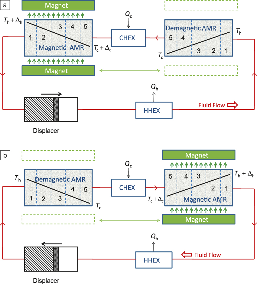
Figure 1 shows an implementationReference Richard, Rowe and Chahine5 of the AMR cycleReference Barclay and Steyert4 with two AMR beds containing MCMs’ porous to fluid flow. This figure assumes MCM temperatures near a paramagnetic to ferromagnetic transition, thus the MCM warms when a magnetic field is applied, and cools when field is removed. In Figure 1a, a displacer drives HTF at a hot outlet temperature T h + Δh through a hot side heat exchanger (HHEX), where the HTF releases heat at a rate Q h to the environment and cools to a hot inlet temperature T h. The HTF enters the hot end of a demagnetized MCM bed on the right. The HTF is cooled as it flows through the MCM to a cold outlet temperature T c and goes to a cold side heat exchanger (CHEX) where the HTF absorbs heat at a rate Q c from the load, warming to a cold inlet temperature T c + Δc. The fluid is directed to the cold end of a magnetized MCM bed on the left. The HTF warms as it flows through the MCM to a temperature T h + Δh and returns to the displacer, completing a fluid cycle. After a HTF blow time (t b), the displacer motion stops. The magnet moves from the MCM beds on the left to the MCM beds on the right in a field change time t m. The displacer reverses motion, which reverses the flow of HTF (Figure 1b). Again, HTF warmed by the magnetized bed releases heat at the HHEX, and HTF cooled by the demagnetized bed absorbs heat from the load. After another period of time t b, the displacer motion stops and the magnet returns to the MCM bed on the left, completing the AMR cycle. The time required for two blow periods and two field changes is the AMR cycle time, and its inverse the cycle frequency. The temperature span of the MHP AMR system is defined as T h – (T c + Δc), the difference in the HTF temperatures at the inlet to the AMR beds.
Schematic of the active magnetic regenerator (AMR) cycle. Fluid flow in the beds reverses when the field changes as the magnet moves from the position shown in diagram (a) to the position shown in diagram (b). The black lines show idealized temperature profiles in the magnetocaloric materials beds. Note: HHEX, hot side heat exchanger; CHEX, cold side heat exchanger; T h, hot inlet temperature; T h + Δh, hot outlet temperature; T c, cold outlet temperature; T c + Δc, cold inlet temperature; Q h, rate of heat release to the environment; Q c, rate of heat absorbed from the environment.

Figure 1 shows the AMR beds divided into five layers numbered 1 at the hot end through 5 at the cold end. HTF entering the demagnetized bed at temperature T h is cooled by the MCM in layer 1 before the HTF reaches layer 2, and so forth, until the last layer 5 cools the HTF to a temperature T c. At the CHEX, the heat load Q c warms the HTF emerging from the cold end of the demagnetized bed through a temperature rise Δc. An efficient situation occurs when the temperature rise Δc equals the magnetocaloric temperature rise ΔT because the fluid arriving at the cold end of the magnetized bed from the CHEX does not suffer a sudden temperature change. For this case, the cooling power for HTF specific heat C pf and average HTF mass flow rate mdot is:
 $$Q_{\rm{c}} = {\rm{mdot}}\,C_{{\rm{pf}}} \Delta T.$$
The HTF entering the magnetized bed is warmed by successive layers of MCM. Because the fluid is successively cooled by MCM in the demagnetized bed and successively warmed by MCM in the magnetized bed, a regenerative effect occurs that allows the AMR span to be much larger than the magnetocaloric ΔT. The heat-transfer area of the MCM in the AMR bed is large if the fluid passages in the MCM have a small hydraulic diameter, which minimizes the temperature difference between fluid and solid in the bed, and allows the carrying of relatively large heat loads Q c.
A useful parameter for describing the HTF flow in an AMR-type MHP is the utilization ratio U, which is the ratio of the thermal capacity of the HTF that flows through an AMR bed in one half cycle to the thermal capacity of the MCM in the AMR bed.Reference Tura and Rowe7 For a flow time in a half-cycle tb, MCM mass m, and MCM average specific heat C pm, the utilization ratio is:
 $$U = {{\left( {{\rm{mdot}}\,{t_{\rm{b}}}\,{C_{{\rm{pf}}}}} \right)} / {\left( {m\,{C_{{\rm{pb}}}}} \right)}}$$
If U > 2, then the AMR bed, acting as a regenerator, will be unable to support a large temperature span.Reference Schmidt and Willmott8 Conversely, if U < 0.1, then the cooling load per cycle will be low, and frictional losses associated with reversing the flow will use up the potential cooling load of the AMR bed.
Layered AMR beds
An important characteristic of the AMR is that each section of the AMR bed sees only part of the total temperature span, and therefore the bed may be layered, with each layer containing an MCM composition with properties optimized for the operating temperature of that layer. When cost effectiveness of a magnetic refrigerator is the primary goal, a good figure of merit is the specific cooling power, the cooling power per unit volume of MCMs. This is because the MCM must fit within the magnet gap, the size and cost of a magnet when optimally designedReference Insinga, Bjørk, Smith and Bahl9 is proportional to its gap volume, and the permanent magnet dominates the cost of an MHP.
The specific cooling power will be proportional to the MCE, so one wants a large MCE, consistent with considerations such as hysteresis losses. If the MCE only comes from the magnetic system, ΔS will be limited by the maximum magnetic entropy of N vln(2J + 1), where N v is the number of spins per unit volume, and J is the total angular momentum quantum number,Reference Kittel10 so a high spin density and a large J are desired. The high density of spins also ensures a large magnetocaloric temperature change ΔT. However, a sum ruleReference Tishin and Spichkin11 also limits the MCE. The sum rule, derived by integrating a Maxwell relation, is:
 $$\int\limits_0^\infty {\Delta S} dT = - {M_S}\Delta H$$,
where M S is the saturation magnetization and ΔH is the change in magnetic field. M S is limited by the density and size of magnetic spins. Thus, a tradeoff must be made between the magnitude of the MCE and the temperature range over which the MCE is large. Fortunately, as previously noted, each MCM layer only sees part of the AMR span. Thus, if ΔS is made large only over the temperature range of the layer, a large maximum ΔS is possible. Generally, the concentration of the ΔS MCE in a narrow temperature range will also enhance the maximum ΔT MCE as well.
MCMs such as Gd with a second-order magnetic phase transitionReference Insinga, Bjørk, Smith and Bahl9 have a relatively broad magnetic transition, and according to the sum rule, a relatively low maximum MCE. Specific cooling power will thus be limited. However, second-order materials are convenient because they can have low hysteresis and low magnetostriction. AMR design is also simplified because precise arrangement of layers is unnecessary.
MCMs with a strongly first-order magnetic phase transition have a narrow temperature range over which the magnetic transition occurs and can have a large maximum MCE by the sum rule.Reference Sandeman12 Such MCMs also have a large magnetic heat capacity, allowing the attainment of a small U even at moderately high HTF flow rates. Operating at small U enables each layer to be operated over a narrow temperature range. If the MCM has a Curie point that can be adjusted with composition, such as can be done by changing y in the series La(Fe1–x–yMnySix)H1.5, one can use a series of layers with successively higher Curie points. Designing an AMR using such materials requires an accurate model of the AMR, consistently synthesized MCM, and precise construction of the layers of the AMR. Long-term stable operation of the AMR also requires stable MCM properties.Reference Zimm and Jacobs13
Heat-transfer fluid flow
The MCM in the AMR bed must be subjected to a large change in magnetic field to produce a substantial magnetocaloric effect. The large magnetic field can be generated by one or more expensive high field magnets. Heat exchangers (HEXs) should be located outside the magnet air gap to reduce the required volume of magnetic material. The HEXs can then be linked by a length of piping to the AMR bed. The practical location of the heat source and heatsink with respect to the AMR may involve long piping runs. An example is the air conditioner of a large building, where the HHEX may be on the building roof, and multiple CHEXs may be located throughout the building.
Low density gaseous HTFs require large flow volumes for large Q c due to their small volumetric heat capacity compared to solid MCMs, resulting in large flow losses and reduced efficiency of the MHP. A solution to this problem is to use a liquid HTF with a high volumetric heat capacity, such as water. In this case, the swept volume at suitable U is similar to the volume of the AMR bed and the volume of the pipes connecting the AMR beds to the HEXs. When the swept volume is similar to the volume of the piping, and a single pipe with bidirectional flow links a HEX to an AMR bed, much of the HTF that flows in the pipe will not see substantial exposure to both the HEX and the AMR bed, and thus cannot transfer heat between the AMR bed and the HEX. This type of loss is commonly called a shuttle loss or a dead volume loss.Reference Liu14
A methodReference Zimm, Jastrab, Sternberg, Pecharsky, Gschneidner, Osborne and Anderson15,Reference Zimm, Boeder, Chell, Sternberg, Fujita, Fujieda and Fukamichi16 to reduce the piping dead volume is to provide two pipes between the cold end of each AMR bed and each CHEX, two pipes between the hot end of each AMR bed and each HHEX, and use valves or other components to cause HTF in the first pipe to flow only in a single direction from the HEX outlet to the AMR bed, and fluid in the second pipe to flow only in a single direction from the AMR bed to the HEX inlet. In this unidirectional pipe flow case, all the fluid that passes though the HEX will eventually also pass through the first pipe and reach the AMR bed, and all the fluid that exits the AMR bed enroute to the HEX will pass through the second pipe and the HEX. An example of this arrangement in Figure 2 shows an AMR cycle with two AMR beds and unidirectional flow in the piping.
A refinement of the arrangement in Figure 1 shown with valves and heat exchangers (HEXs) that produces unidirectional flow of the heat-transfer fluid (HTF) in the piping to reduce dead volume losses. (a–b) Two successive magnet positions and corresponding HTF flows. Note: MCM, magnetocaloric materials; Q c, rate of heat absorbed from the environment; Q h, rate of heat released to the environment; T ci, inlet temperature at the cold side of the MCM bed; T co, outlet temperature at the cold side of the MCM bed; T hi, inlet temperature at the hot side of the MCM bed; T ho, outlet temperature at the hot side of the MCM bed.

Rotary AMR MHPs
For MHPs with reciprocating motion, inertial forces will limit the maximum frequency, and magnetic forcesReference Teyber, Meinhardt, Thomsen, Polikarpov, Cui, Rowe, Holladay and Barclay17 varying rapidly with the relative position of the magnet and the MCM can reduce drive efficiency. Such problems can be reduced when multiple AMR beds are arranged in a wheel, with rotary relative motion between the beds and the magnet.
An example of a rotary MHP is a device demonstrated in 2001 with Gd, and subsequently with Gd-Er alloys and La(Fe1–xSix)13Hy.Reference Zimm, Boeder, Chell, Sternberg, Fujita, Fujieda and Fukamichi16 MCM is cycled between low and high magnetic fields by the continuous rotation of a wheel of MCM through the gap of a 1.5 T permanent magnet. Work from the portion of MCM entering the high field region is recovered via the structure of the wheel to assist in removing the portion of MCM leaving the high field region. Figure 3 shows a fluid flow diagram of the device.Reference Zimm, Boeder, Chell, Sternberg, Fujita, Fujieda and Fukamichi16 The wheel is divided into three sectors, each packed with porous MCM. Radial pipes carry water HTF from the CHEX into the middle of each sector and remove HTF into the HHEX from the ends of each sector while the sector is in the gap of the magnet. HTF is carried in the opposite direction when the sector is outside the magnet, thus producing reciprocating circumferential fluid flow in each sector. The HTF flow makes the ends of each sector the hot ends of two AMR matrices, and the middle of the sector becomes the common cold end of the two AMR matrices. Thus the wheel contains six AMR matrices.
Rotary magnetic heat pumping using the concepts described in Reference Zimm, Boeder, Chell, Sternberg, Fujita, Fujieda and FukamichiReference 16. Rotating active magnetic regenerator beds with co-rotating hot (top) and cold (bottom) valve disks pass through low (unmarked) and high field (black dashed line) regions while heat-transfer fluid flow (shaded green arrows) reverses. Note: HHEX, hot side heat exchanger; CHEX, cold side heat exchanger; Q c, rate of heat absorbed from the environment; Q h, rate of heat released to the environment.

The radial pipes at the hot ends of the AMR bed sectors are connected to ports in a rotating part of a disk valve located above the plane of the wheel. The contact faces of the rotor and stator are highly polished, so that no fluid can leak between them. The fixed portion of the upper valve is connected to the inlet and outlet of the HHEX and to a pump. The radial pipes at the cold middle of each sector are connected to ports in a rotating part of a disk valve below the plane of the wheel. The fixed portion of the lower valve is connected to the inlet and outlet of the CHEX. The ports in the rotating and fixed parts of the disk valves interact to correctly switch fluid flow as the wheel rotates. The surface speed of the disk valve is low because it is centered on the rotational axis, thereby minimizing frictional losses. Although the fluid flow in the matrices reverses in direction, the piping and valve switching is set up so that the pump runs continuously and flow in the pipes and heat exchangers is unidirectional, minimizing dead volume. The valve arrangement and flow circuit allows the machine to operate smoothly and reliably over a range of frequencies up to 4 Hz, with low noise and vibration.Reference Zimm, Boeder, Chell, Sternberg, Fujita, Fujieda and Fukamichi16
An alternate rotary implementation uses a magnet assembly with a gap rotating over fixed beds of MCM.Reference Lozano, Capovilla, Trevizoli, Engelbrecht, Bahl and Barbosa18,Reference Eriksen, Engelbrecht, Bahl, Bjørk, Nielsen, Insinga and Pryds19 This arrangement avoids the need for rotary seals to the beds. A MHPReference Jacobs, Auringer, Boeder, Chell, Komorowski, Leonard, Russek and Zimm20 developed in 2013 used a 1.44 T magnet assembly rotating over 12 fixed beds arranged circumferentially. Four rotary valves controlled the HTF flow, corresponding to the four valves in Figure 2. Piping was arranged similar to Figure 2 to obtain unidirectional flow. The AMR beds contained a total of 1.52 kg of MCM, composed of six layers of spherical particles of La(Fe1–xSix)13Hy. Each layer had a first-order magnetic transition at a different temperature. This MHP produced a cooling power of 2500 W over a span of 11 K with a COP of 1.9 at a water HTF flow rate of 21.2 l per min. The COP is defined as the cooling load of the MHP divided by the electrical power consumption (power required by the motor driving the magnet and valve motion plus power required by the HTF pump).
Variations on the AMR
The 2013 rotary multiport valve, rotary magnet spherical particle bed AMRReference Jacobs, Auringer, Boeder, Chell, Komorowski, Leonard, Russek and Zimm20 previously described produced significant cooling power at a respectable COP. However, to compete effectively with the vapor cycle, both the COP and the specific cooling power need to be much higher. Alternative approaches are being explored by a number of investigators.Reference Kitanovski, Tušek, Tomc, Plaznik, Ozbolt and Poredoš21,Reference Gatti, Muller, Vasile, Brumpter, Haegel and Lorkin22
The 2013 rotary MHP used MCM beds comprised of packed spherical particles of La(Fe1–xSix)13Hy packed in layers of different y. This bed geometry is easy to fabricate, but has relatively high HTF pressure drop and thermal dispersion losses. Alternative geometries such as parallel channels could have much lower losses. However, fabrication is difficult for hydraulic diameters small enough to offer good heat transfer between the MCM and the HTF.
The 2013 rotary MHP had fairly long lines of piping running between the HTF control valves and the MCM beds. Although the flow in these lines did not reverse, the flow was intermittent, and fluid inertia limits operating frequency and specific cooling power. An approach to increase the frequency is to associate each AMR MCM bed with a control valve located as close as possible to the AMR bed.Reference Schmidt and Willmott8
Improved thermal contact between MCM and HTF might occur with a liquid-metal HTF, such as mercury, or the gallium-indium-tin alloy galinstan.Reference Kitanovski, Tušek, Tomc, Plaznik, Ozbolt and Poredoš21 Issues with this approach are eddy currents in the fluid/MCM matrix induced by the changing field, reaction between the HTF and the MCM, thermal conduction from hot to cold ends of the AMR beds, and freezing of the HTF at low temperatures. Alternatively, the HTF could be replaced by moving plates of metal such as copper or brass in direct physical and thermal contact with plates of MCM.Reference Zhang, Mehdizadeh Momen and Abdelaziz23 Issues with this approach are frictional losses between the moving plates and the MCM, limited thermal conduction at the contacts, and longitudinal conduction along the moving metal plates. If the moving metal plates were laminated to have high conduction normal to their surface and low conduction along their length, longitudinal conduction could be reduced.
Conclusions
Progress has been made in MHPs, but more work is required to enable widespread application and cost effectiveness. Two areas for future work include developing improved MCMs with larger MCE, and developing economical fabrication techniques for effective AMR regenerators. Improved MCMs will have larger MCE and must be stable under long-term exposure to suitable HTF and cycling magnetic fields. Requirements for improved AMR regenerators include producing regenerators with small hydraulic diameters to promote heat transfer with good uniformity to minimize dispersion. Fabrication techniques are needed to economically mass produce the improved regenerators using improved MCMs.

Carl Zimm is an engineer at the Astronautics Corporation of America. He received his PhD degree in physics from Cornell University in 1982. He completed postdoctoral research on magnetocaloric materials at Los Alamos National Laboratory. His current work focuses on magnetic heat-pumping systems. Zimm can be reached by email at c.zimm@astronautics.com.
Andre Boeder is an engineer at the Astronautics Corporation of America. He received his BS degree in mechanical engineering from the University of Wisconsin–Madison. His current work focuses on magnetic heat-pump testing, and design of fluid and thermal systems. Boeder can be reached by email at a.boeder@astronautics.com.

Bryant Mueller is an engineer at the Astronautics Corporation of America. He received his BS and MS (2012) degrees in mechanical engineering from the University of Wisconsin–Madison. His research interests include modeling, building, and testing of magnetic heat-pump systems. Mueller can be reached by email at b.mueller@astronautics.com.

Kyle Rule is an engineer at the Astronautics Corporation of America. He received his BS and MS degrees in mechanical engineering from the University of Wisconsin–Madison. Prior to joining Astronautics Corporation of America, he was an engineer for Creare, and his projects included turbomachine design and analysis, high-effectiveness heat-exchanger design, and test facility design for low-temperature cryocoolers. His current research interests include thermal and fluid energy systems, turbomachine design and development, cryogenics, and heat-exchanger design and analysis.

Steven L. Russek has been director of the Astronautics Technology Center at Astronautics Corporation of America since 2002. He leads the technical and business aspects of Astronautics’ magnetic refrigeration development program. He received his PhD degree in chemical engineering from the University of California, Berkeley, in 1993. He has more than 25 years of experience leading the research, development, engineering, and business development aspects of new process technologies, which integrate novel materials. He has also served as the director of Systems Engineering and as the senior program manager for Astronautics’ A400M Airborne Network Server System. Russek can be reached by email at s.russek@astronautics.com.