I. INTRODUCTION
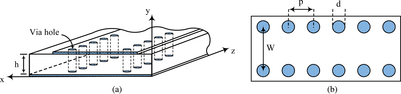
Equal or unequal power dividers are key passive components in many microwave and millimeter-wave systems, such as power amplifiers and the feeding network of antenna arrays [Reference Khan and Mandal1, Reference Kouhpayeh-Zadeh-Esfahani, Afrooz and Moradi2]. High cost and large size have limited the application of the traditional waveguide power dividers. Furthermore, these power dividers are difficult to be integrated with planar circuits [Reference Moznebi and Afrooz3]. Recently, substrate-integrated waveguide (SIW) structure has been introduced by two parallel rows of periodic via holes in a planar substrate as shown in Fig. 1 [Reference Uchimura, Takenoshita and Fujii4, Reference Yan, Hong, Wu and Cui5]. The SIW solution allows an easy integration of power dividers with planar circuits alongside the benefits of the low cost and low loss [Reference Bozzi, Georgiadis and Wu6]. Nevertheless, it is observed that, in most of the proposed power dividers, the circuit size is relatively large [Reference Contreras and Peden7–Reference Moznebi and Afrooz9]. For example, two SIW T-junctions for equal and unequal two-way power dividers are studied in [Reference Contreras and Peden7, Reference Li and Dou8]. These structures suffer from the disadvantages of the big size and large insertion loss.
Configuration of the SIW structure: (a) solid view, (b) top view.

The evanescent-mode technique is a known solution to miniaturize the size of the SIW circuits [Reference Esteban, Camacho-Peñalosa, Page, Martín-Guerrero and Márquez-Segura10]. This technique provides an additional forward passband below the SIW cutoff frequency by loading the electric dipoles on the metal cover of the SIW structure [Reference Wu, Zhou, Yin, Zhou and Mao11]. The complementary split-ring resonators (CSRRs) behave as electric dipoles and their combination with SIW structure is investigated in [Reference Dong, Yang and Itoh12]. In addition to miniaturization, these resonators are able to enable the filtering function of the power divider. Combining a power divider with a bandpass filter is beneficial and can reduce the circuit area and interconnection loss. In [Reference Danaeian, Moznebi, Afrooz and Hakimi13], an SIW power divider with arbitrary power division ratio loaded by CSRRs is introduced. However, this design has transmission zeros only in the upper stopband for the case of equal power division among the output ports.
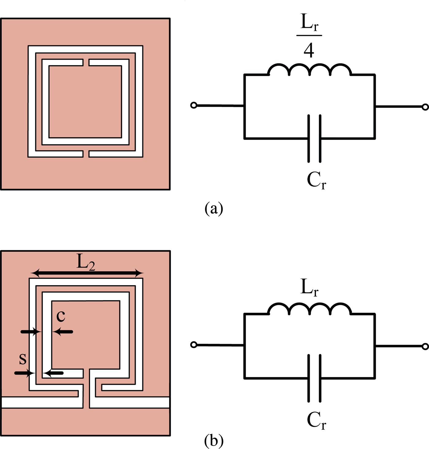
The typical layout of the open complementary split-ring resonators (OCSRRs) is depicted in Fig. 2. As can be seen in this figure, the OCSRR can be derived from the CSRR by opening it [Reference Velez, Aznar, Bonache, Velazquez-Ahumada, Martel and Martin14]. The OCSRR can also be considered in terms of electric dipoles and exhibit similar abilities [Reference Velez, Aznar, Bonache, Velazquez-Ahumada, Martel and Martin14, Reference Durán-Sindreu, Aznar, Vélez, Bonache and Martín15]. The inductance of this resonator (L r ) is the inductance of the metallic strip between the ring slots, and its capacitance (C r ) is the capacitance of the CSRR. C r is the edge-to-edge equivalent capacitance of a square slot ring with a length of L 0-c/2 (where L 0 = L 2-c-s/2 is the averaged length) surrounded by a metallic plane at a distance “c” of its edge [Reference Durán-Sindreu, Aznar, Vélez, Bonache and Martín15]. The detailed calculation of C r is reported in [Reference Durán-Sindreu, Aznar, Vélez, Bonache and Martín15]. Consequently, as can be seen in Fig. 2, the inductance of the CSRR is one-quarter of the OCSRR; therefore, the resonance frequency of the OCSRR is one-half of the resonance frequency of the CSRR with the same size. Accordingly, the electrical size of the OCSRR is larger than the electrical size of the CSRR and more miniaturization can be achieved by loading this resonator on the SIW structure. In [Reference Danaeian, Afrooz, Hakimi and Moznebi16], two compact SIW bandpass filters loaded by two types of the OCSRR unit cells have been reported for the first time.
Layout and equivalent circuit: (a) CSRR, (b) OCSRR.

In this paper, a miniaturized SIW power divider with arbitrary power-dividing ratio loaded by OCSRRs is proposed. With the employment of the OCSRR unit cells, a size reduction and bandpass filtering response are achieved, simultaneously. Finally, the validity of this structure is confirmed by fabricating three power dividers with different power division ratios (1:1, 1:4, and 1:8). The measured results show reasonable agreement with the simulated results. Moreover, the proposed structure shows the significant advantages in terms of high selectivity, controllable bandwidth, and high-power division ratio.
II. ANALYSIS AND DESIGN
A) SIW design
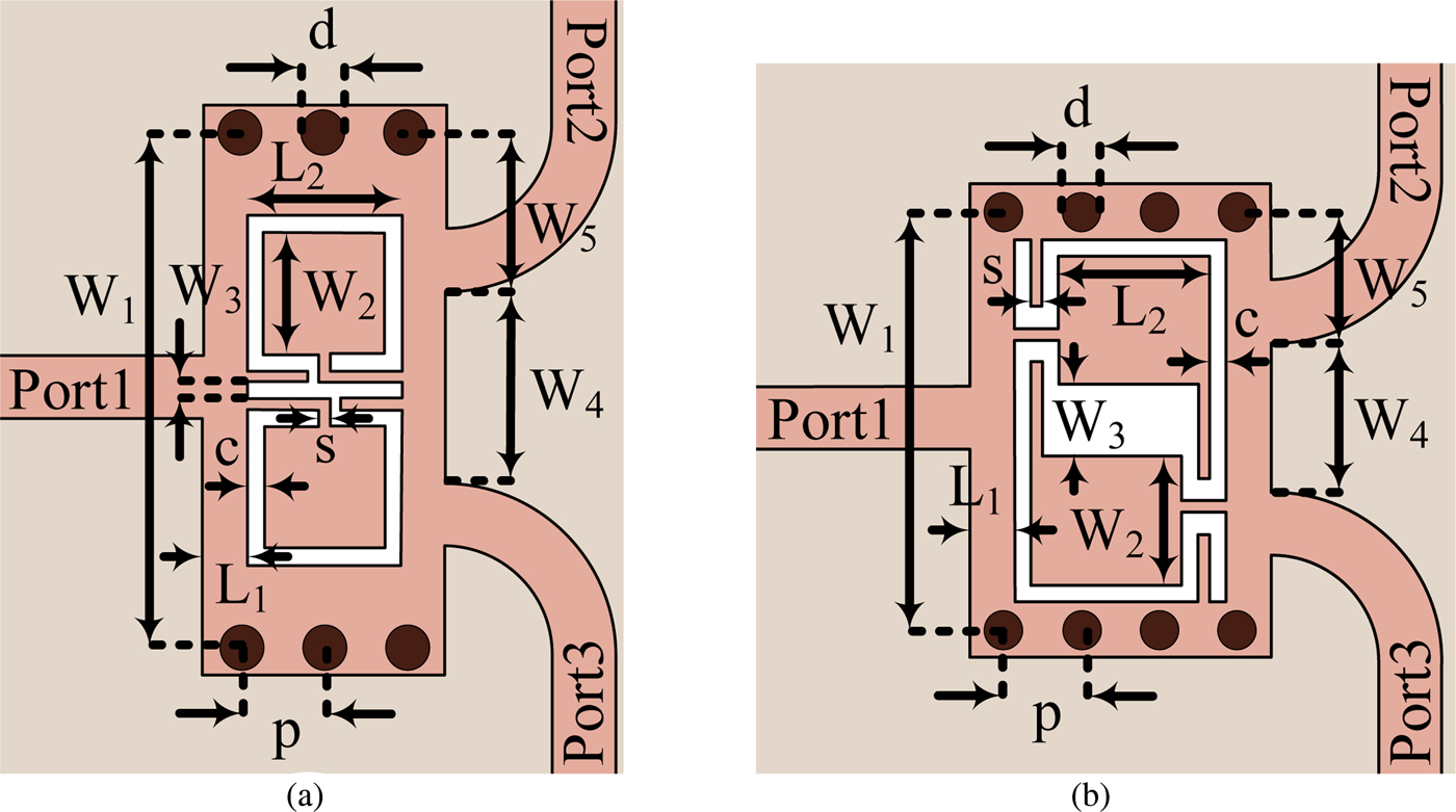
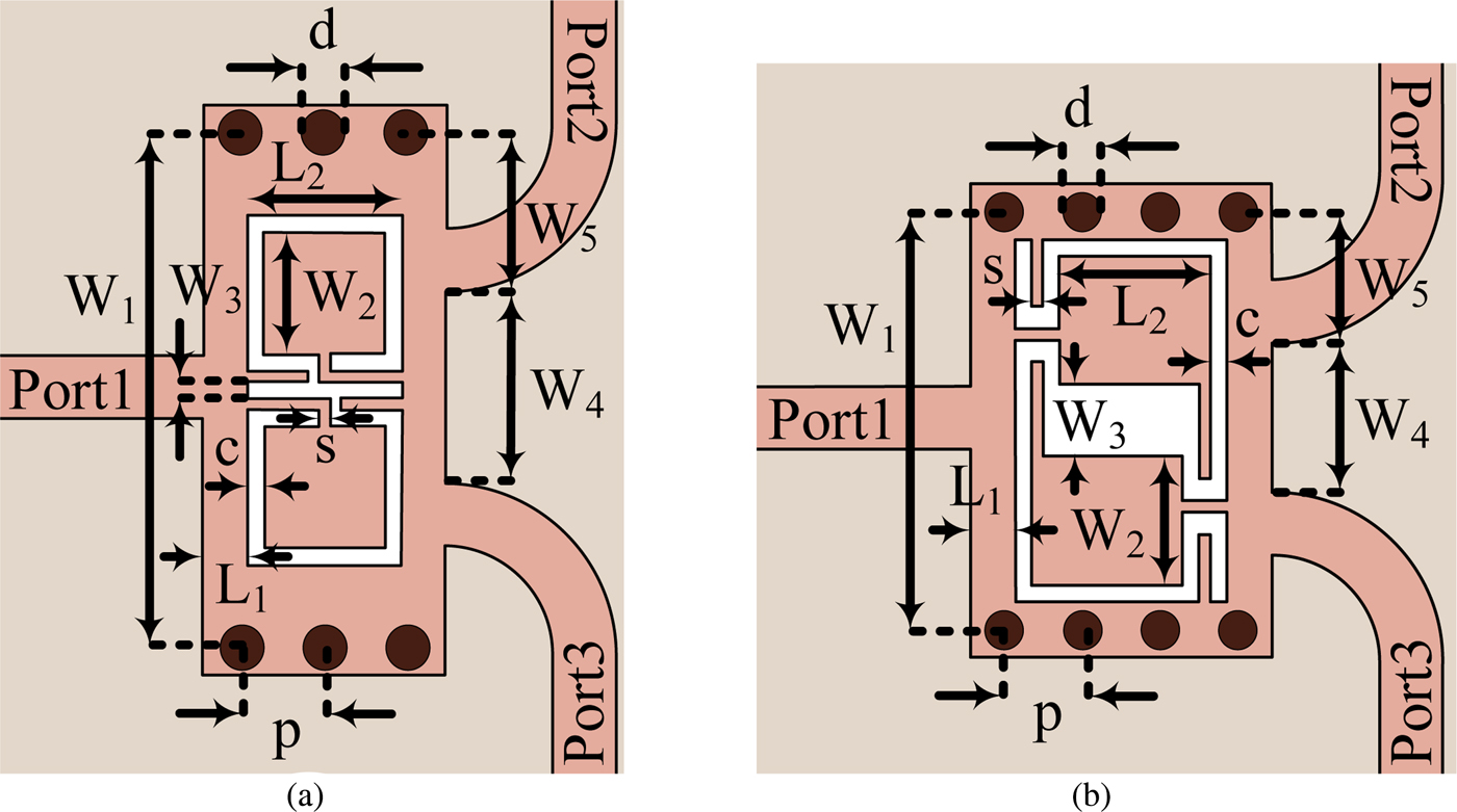
The configurations of the proposed power dividers are shown in Fig. 3. To design the SIW structures, d (diameter of vias) and p (distance between two adjacent vias) are limited by p ≤ 2d [Reference Wu, Deslandes and Cassivi17]. In these structures, the dominant mode of the SIW is TE 10, which its cutoff frequency can be achieved by using the formula reported in [Reference Pozar18]:
 $$f_{c10} = \displaystyle{c \over {2W_{eff}\sqrt {\mu _r\varepsilon _r}}}. $$
In (1), c is the velocity of light in the free space, μ r is the relative permeability of the substrate, ε r is the relative permittivity of the substrate, and W eff is the equivalent width of the SIW, which is presented in [Reference Xu and Wu19]. Nevertheless, the proposed power dividers have an additional passband below the SIW cutoff frequency.
Layout of the proposed power dividers: (a) type I, (b) type II.
B) OCSRR unit cells design
As can be seen in Fig. 3, type I structure is achieved by etching a pair of OCSRRs oriented face-to-face, and type II structure is obtained by etching a pair of OCSRRs oriented side-by-side reversely. The OCSRRs are modeled as a shunt resonator tank with inductance L r and capacitance C r . Accordingly, the resonance frequency of the OCSRR is obtained from [Reference Ferran20]:
 $$f_r = \displaystyle{1 \over {2\pi \sqrt {L_rC_r}}}. $$
In the layout of the proposed power dividers, the parameters of c, s, L 2, and W 2 are the key parameters of the OCSRR unit cells. By resizing these parameters, the amount of inductance L r and capacitance C r are changed and the resonance frequency of the passband can be easily changed. Therefore, the frequency response of the proposed power dividers can be easily moved. It is important to note that these parameters have not effect on the power division ratio.
C) Filter design
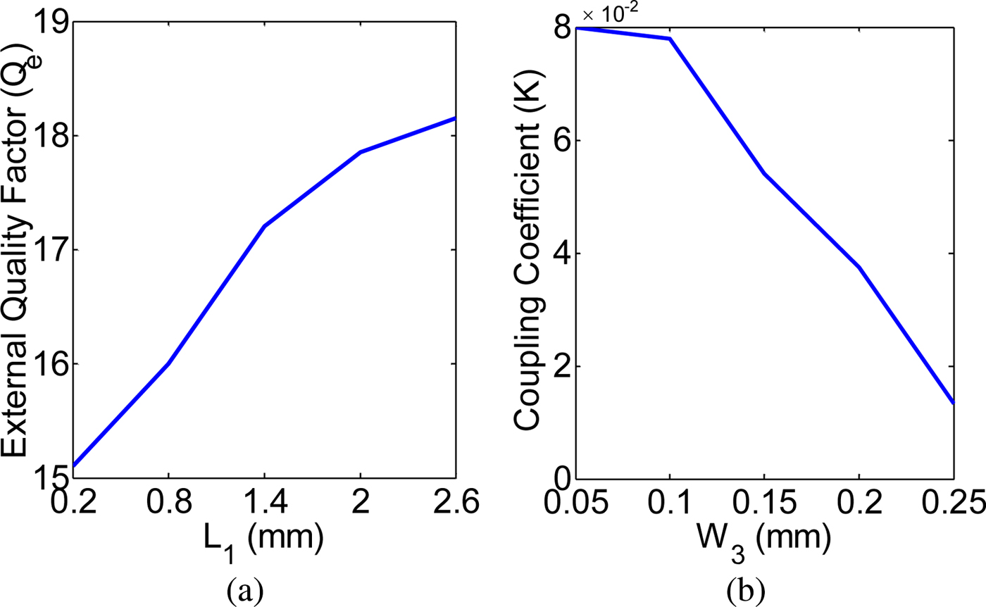
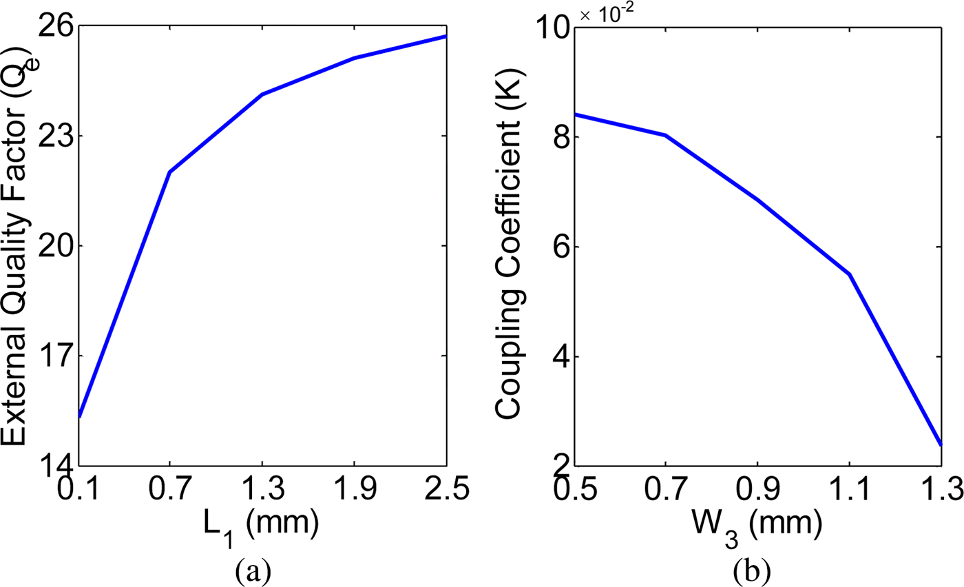
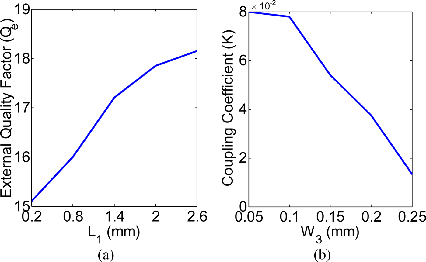
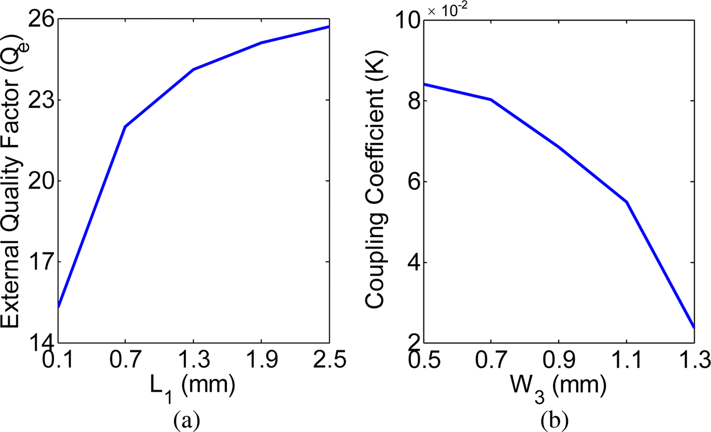
To design the desired bandpass filter response applied in the proposed power dividers, the external quality factor and coupling coefficient are specified by the circuit elements of a low-pass prototype filter at first [Reference Hong and Lancaster21]. Then, the physical parameters of L 1 (length of the SIW structure between the OCSRRs and input/output ports) and W 3 (width of the removed metal strip line in the middle of the two OCSRRs) are varied in a three-dimensional electromagnetic simulator to determine the relationship between them and the external quality factor and coupling coefficient. The external quality factor and coupling coefficient for types I and II are shown in Figs 4 and 5, respectively, which are achieved by following equations [Reference Hong and Lancaster21]:
 $$Q_e = \displaystyle{{2f_0} \over {BW}},$$
 $$K = \displaystyle{{f_1^2 - f_2^2} \over {f_1^2 + f_2^2}}, $$
where f 0 is the resonance frequency, BW is the 3 dB bandwidth, and f 1 and f 2 are the higher and lower resonant frequencies of the coupled resonators. According to Figs 4 and 5, the parameters of L 1 and W 3 can be obtained. As can be seen, the external quality factor can be increased by increasing L 1, and coupling coefficient can be decreased by increasing W 3. In this design, the considered external quality factor and coupling coefficient are 16 and 0 for type I structure and 22 and 0.025 for type II structure.
(a) External quality factor of the proposed power divider (type I) as a function of L 1, (b) coupling coefficient of the proposed power divider (type I) as a function of W 3.
(a) External quality factor of the proposed power divider (type II) as a function of L 1, (b) coupling coefficient of the proposed power divider (type II) as a function of W 3.
D) Analysis of power division ratio
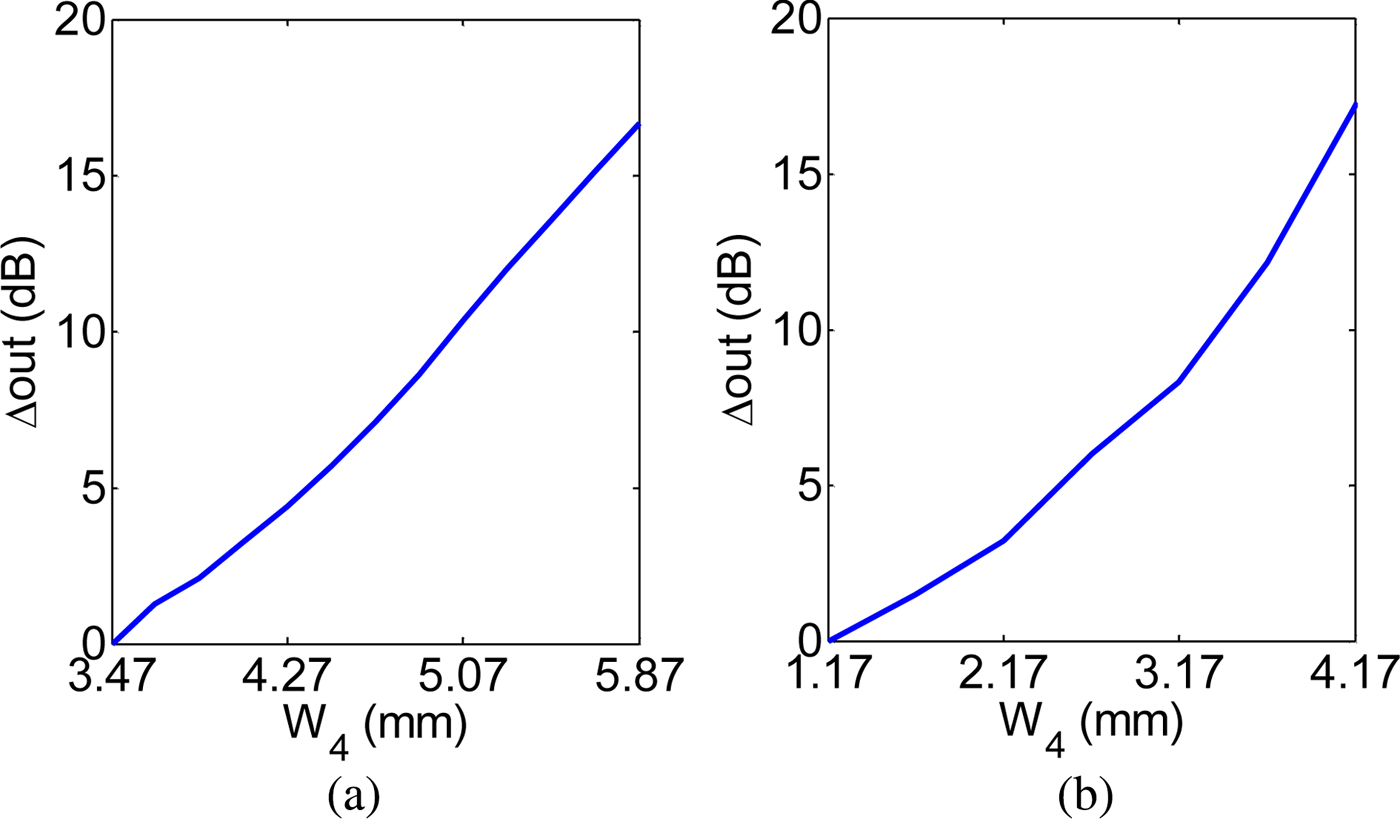
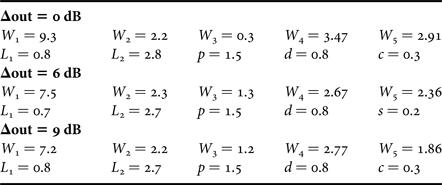
As shown in Fig. 6, the power division ratio of the proposed structures can be adjusted by altering the value of W 4 (distance between the two output ports). For both cases, the power division ratio can be increased by raising W 4. It should be mentioned that when the output ports are symmetry, type I structure has the power division ratio of 1:1 (because of the symmetry of the OCSRRs loaded face-to-face oriented), and type II structure has the power division ratio of 1:4 (because of the asymmetry of the OCSRRs loaded side-by-side reversely oriented). In this paper, a power divider with power division ratio of 1:1 is presented by type I structure, and two power dividers with power division ratios of 1:4 and 1:8 are realized by type II structure. The design parameters of the proposed power dividers are listed in Table 1.
The Δout of the proposed power dividers as a function of W 4: (a) type I, (b) type II.

Design parameters of the proposed power dividers; dimensions in millimeters.

III. EXPERIMENTAL RESULTS
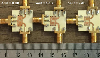
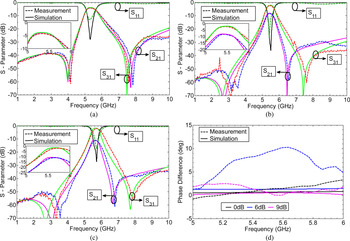
The photograph of the fabricated power dividers with power division ratios of 1:1, 1:4, and 1:8 is shown in Fig. 7. The applied substrate for three power dividers is Rogers RO4003C substrate with a thickness of 0.508 mm, dielectric permittivity of 3.55, and loss tangent of 0.0027. The simulated and measured results are summarized in Fig. 8. As can be seen, the measured results are in good agreement with the simulated results. According to this figure, the equal power divider has a 3 dB bandwidth of 740 MHz in 5.02–5.76 GHz frequency band. The measured in-band insertion loss and return loss are 1.3 dB and better than 13 dB, respectively. Moreover, the measured results illustrate Δout is <0.05 dB (Δout is the imbalance in the magnitude of the two output ports) and Δphase is <2°. The unequal power divider with Δout = 6 dB has a 3 dB bandwidth of 460 MHz in 5.24–5.7 GHz frequency band. The measured in-band insertion loss and return loss are 1.4 dB and better than 26 dB, respectively. In addition, the measured results illustrate Δout is <Δout ± 5% and Δphase is <10°. The unequal power divider with Δout = 9 dB has a 3 dB bandwidth of 510 MHz in 5.43–5.94 GHz frequency band. The measured in-band insertion loss and return loss are 1.6 dB and better than 17 dB, respectively. Moreover, the measured results illustrate Δout is <Δout ± 7.5% and Δphase is <1°.
Photograph of the fabricated power dividers.

S-parameters of the proposed power dividers with power division ratios of: (a) 1:1, (b) 1:4, (c) 1:8, and (d) differential phase of the proposed power dividers with power division ratios of 1:1, 1:4, and 1:8.

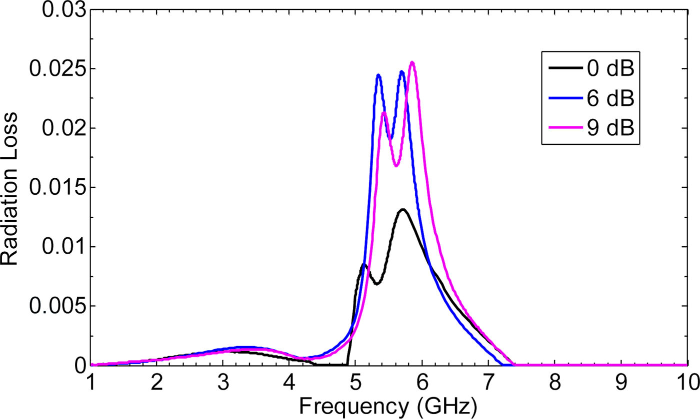
The radiation loss for three power dividers is appeared due to the slots patterned on the top conducting surface of the SIW structure. The normalized radiation loss for these power dividers can be calculated by:
 $$R_r = 1 - S_{11}S_{11}^* - S_{21}S_{21}^* - S_{31}S_{31}^*, $$
under the conditions of lossless substrate and metal. Figure 9 shows the radiation losses of the proposed power dividers (1:1, 1:4, and 1:8), which are negligible and <0.013, 0.024, and 0.025, respectively.
Radiation loss of the proposed power dividers.

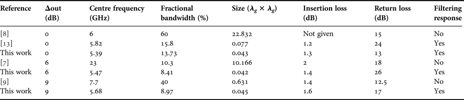
A performance comparison with the previous power dividers is given in Table 2. As can be seen, the proposed power dividers have an advantage in terms of selectivity and size. The proposed power dividers (1:1, 1:4, and 1:8) have the overall sizes of 0.31λ g × 0.14λ g , 0.25λ g × 0.17λ g , and 0.25λ g × 0.18λ g , respectively.
Comparison between relative power dividers.

IV. CONCLUSION
In this paper, a miniaturized SIW power divider with embedded filter response and arbitrary power-dividing ratio loaded by OCSRRs has been proposed. A design procedure is established for the filter design and power adjustment of the proposed power dividers. Three SIW power dividers with bandpass response and different power division ratios of 1:1, 1:4, and 1:8 are fabricated and tested to verify the validity of the above design method. The measured results show reasonable agreement with the simulated results. The dimensions of the presented power dividers compared with other power dividers have been much reduced, which verified the ability of the reported filtering SIW power dividers in the size reduction.
 Mostafa Danaeian was born in Yazd, Iran, in 1985. He received the B.Sc. degree in Electrical Engineering from Yazd University, Yazd, Iran, in 2008, the M.S. degree in Electrical Engineering from Shahid Bahonar University of Kerman, Kerman, Iran, in 2011, and is currently working toward the Ph.D. degree at the Shahid Bahonar University of Kerman, Kerman, Iran. His research interests are MTM, RF/microwave circuits design. He is currently involved with microwave filters based on CRLH and ARLH structures.
 Ali-Reza Moznebi received the B.S. degree from O.T.F. University, Fars, Iran, in 2013, and the M.S. degree from the Shahid Bahonar University of Kerman, Kerman, Iran, in 2016, both in Electrical Engineering. He is currently working toward the Ph.D. degree in Electrical Engineering at Shahid Bahonar University of Kerman. His research interests include microwave/millimeter-wave power-dividing technology and microwave/millimeter-wave devices, circuits, and systems. He is also the recipient of the Outstanding Student Award in the Faculty of Engineering in 2016.
 Kambiz Afrooz was born in Baft, Iran, in 1983. He received the B.Sc. degree from the Shahid Bahonar University of Kerman, Kerman, Iran, in 2005, the M.Sc. and Ph.D. degrees from the Amirkabir University of Technology (Tehran Polytechnic), Tehran, Iran, in 2007 and 2012, all in Electrical Engineering. In May 2011, he joined the CIMITEC group, University Autonoma de Barcelona (UAB), Barcelona, Spain, as a Visiting Student. He is currently an Associate Professor with the Electrical Engineering Department, Shahid Bahonar University of Kerman, Kerman, Iran. His research interests are in the areas of computer-aided design of active and passive microwave devices and circuits, computational electromagnetic, modeling and simulation of high-speed interconnects, metamaterial transmission lines, and substrate-integrated waveguide structures. He is also the recipient of the Electrical Engineering Department Outstanding Student Award in 2007.
 Ahmad Hakimi was born in Rafsanjan, Iran, in 1961. He received his B.Sc. degree in Electrical Engineering from Technical College of Shahid Bahonar University of Kerman, Kerman, Iran, in 1986. Using the scholarship granted by the Ministry of Higher Education of Iran and Istanbul Technical University (ITU) in 1987, he has been studying for his M.Sc. and Ph.D. degrees in the Faculty of Electrical and Electronic Engineering at the ITU. He received his M.Sc. and Ph.D. degrees from ITU in 1996 and 1995 in the field of High-Frequency Electronics. His research interests include design and analysis of non-linear RF circuits, numerical analysis and advanced engineering mathematics, analog filter design, and linear integrated circuits. He is currently with the Scientific and Industrial Research Center, Kerman, Iran, and the Department of Electrical Engineering, Shahid Bahonar University of Kerman, Kerman, Iran.