I. INTRODUCTION
Mesoporous single crystals have been a matter of discussion in the last years in the context of solar hydrogen generation, since it is expected that this material class can contribute significantly to the improved design of highly efficient solar cell devices. Reference Ducati1 Especially in photocatalysis or photoelectrochemistry, high surface area and good charge transport properties are central prerequisites for enhanced device performance. Reference Walter, Warren, McKone, Boettcher, Mi, Santori and Lewis2,Reference Hisatomi, Kubota and Domen3 The best conductivity for a given material is usually provided by defect free structures, such as large single crystals, but the specific surface area is small. High surface area, however, is reached best by an agglomeration of nanoparticles. In consequence, the conductivity is low because of multiple grain or particle boundaries. One possibility to achieve performance improvement consists in the fabrication of nanostructured thin films with high crystalline quality, where the surface is enhanced, but the charge transport is not affected. The effects of different kinds of nanostructuring procedures on the photoelectrochemical performance, in comparison to single crystals or nanoparticles, have been studied extensively on the example of Fe2O3 electrodes by Kay et al., Reference Kay, Cesar and Grätzel4 and have been summarized by Osterloh. Reference Osterloh5 Finding a better trade-off between large surface area and undiminished charge transport properties is still considered as one of the most important parameters to obtain better device performance. Reference Hisatomi, Kubota and Domen3,Reference Tilley, Cornuz, Sivula and Grätzel6,Reference Landsmann, Maegli, Trottmann, Battaglia, Weidenkaff and Pokrant7 Recently a new concept has been proposed: the synthesis of micrometer-sized mesoporous single crystals. Reference Crossland, Noel, Sivaram, Leijtens, Alexander-Webber and Snaith8 The superior conductivity of mesoporous TiO2 single crystals in comparison to nanocrystalline material has been shown as well as their increased surface area. Following this concept, we have investigated a different material class, very well known for its favorable photocatalytic and photoelectrochemical properties: the oxynitrides, Reference Maeda9 specifically the perovskite-related LaTiO2N (LTON).
One of the synthesis methods to transform precursor oxide powders into oxynitrides is the thermal ammonolysis, a solid gas-phase reaction. Reference Ebbinghaus, Abicht, Dronskowski, Müller, Reller and Weidenkaff10 Several groups have observed that pores are formed in some of the compounds during ammonolysis, if the reaction is carried out without flux, for example in LaTaON2, Reference Park and Kim11 EuTi(O,N)3, Reference Sagarna, Rushchanskii, Maegli, Yoon, Populoh, Shkabko, Pokrant, Lezaic, Waser and Weidenkaff12 TaON, and Ta3N5. Reference Higashi, Domen and Abe13 At present, LTON is the material, which has been studied most intensively in terms of morphology and its influence on the photocatalytic properties in addition to a thorough physical and chemical characterization. Reference Zhang, Yamakata, Maeda, Moriya, Takata, Kubota, Teshima, Oishi and Domen14–Reference Maegli, Hisatomi, Otal, Yoon, Pokrant, Graetzel and Weidenkaff17 In all material systems mentioned above the shape and the size distributions of the precursor oxide particles were preserved during ammonolysis without flux, independent of the crystalline quality and the average size range of the precursor. Reference Park and Kim11,Reference Higashi, Domen and Abe13,Reference Zhang, Yamakata, Maeda, Moriya, Takata, Kubota, Teshima, Oishi and Domen14 Under synthesis conditions without flux mesopores or nanopores were observed as a function of the precursor oxide. Reference Maegli, Pokrant, Hisatomi, Trottmann, Domen and Weidenkaff15 In the case of LTON, mainly two different precursor oxide morphologies have been used for the thermal ammonolysis of La2Ti2O7 (LTO). On the one hand, large brick shaped single crystalline LTO particles were synthesized via a solid state (SS) chemistry route with an average size larger than 1 µm leading to porous single crystalline SS-LTON particles. Reference Maegli, Pokrant, Hisatomi, Trottmann, Domen and Weidenkaff15,Reference Feng, Luo, Fang, Lv, Wang, Gao, Liu, Yu, Li and Zou16 Wagata et al. studied the influence of different flux types and quantities on the growth of SS-LTO to obtain LTO and consequently LTON particle shapes with higher aspect ratios. Reference Wagata, Zettsu, Yamaguchi, Nishikiori, Yubuta, Oishi and Teshima18 On the other hand, small LTO particles (50–300 nm) with lower crystalline quality were obtained via a polymerized complex (PC) route leading to porous PC-LTON particles in the same size range as the precursor PC-LTO. Reference Maegli, Pokrant, Hisatomi, Trottmann, Domen and Weidenkaff15 As expected, the micrometer-sized single-crystalline SS-LTON achieved superior results in terms of photocatalytic and photoelectrochemical properties compared to PC-LTON. Reference Maegli, Pokrant, Hisatomi, Trottmann, Domen and Weidenkaff15,Reference Feng, Luo, Fang, Lv, Wang, Gao, Liu, Yu, Li and Zou16 In the photoelectrochemical case, three reasons for the success of SS-LTON were mentioned: first, the enhanced surface area due to the presence of mesopores. Second, for the same electrode thickness the electrons need to cross less interparticle boundaries to reach the back contact, since SS-LTON consists of large micrometer-sized particles. Third, the brick-like shape which allowed for better stacking of the particles within the electrode. Reference Landsmann, Maegli, Trottmann, Battaglia, Weidenkaff and Pokrant7,Reference Feng, Luo, Fang, Lv, Wang, Gao, Liu, Yu, Li and Zou16 It was assumed that the enhanced contact area facilitated charge transfer and contributed hence to the improved performance. Therefore, investigating the shape of the precursor SS-LTO and shining light on the transformation mechanism of SS-LTO to SS-LTON is an important task, since it has the potential to control the pore size and the particle shape of SS-LTON and hence influence the device efficiency of photoeletrochemically active electrodes for solar water-splitting.
Up to now, the transformation from monoclinic PC-LTO to orthorhombic PC-LTON has been studied in detail with several transmission electron microscopy (TEM) methods. Reference Pokrant, Cheynet, Irsen, Maegli and Erni19 It was found that the pores in PC-LTON were faceted belonging to the {200} and the {121} plane families of the orthorhombic structure with Imma space group. Reference Yashima, Saito, Nakano, Takata, Ogisu and Domen20 It was proposed that the pores were formed to compensate for the unit cell volume reduction taking place during the transformation from PC-LTO to PC-LTON. The size and the number of pores were assumed to be connected to the crystal defect density. In this context SS-LTON was mentioned which showed faceted pores with faces parallel to the same crystal plane families as in PC-LTON. Reference Pokrant, Cheynet, Irsen, Maegli and Erni19 But the pores in SS-LTON were larger, since less crystal defects were present in the micrometer-sized monocrystalline particles than in polycrystalline PC-LTON particles with about only one 10th of the size.
In this work, we aim for an in-depth study of particle shape and pores in SS-LTON. Based on TEM, scanning-TEM (STEM), and electron diffraction, we will show which SS-LTON particle shapes in terms of aspect ratio and which types of pores and pore morphologies can be obtained out of SS-LTO particles during thermal ammonolysis and give an explanation for the formation mechanism.
II. EXPERIMENTAL SECTION
SS-LTO was prepared out of La2O3 (Alfa Aesar, Ward Hill, Massachusetts, ≥99.99%), and TiO2 (Anatase, Sigma–Aldrich, St. Louis, Missouri, >99%) powders which were dried for 4 h at 500 °C. NaCl (VWR, Radnor, Pennsylvania, >99.9%) was used as flux. The oxides were added in stoichiometric ratios to the flux (100 Eq based on TiO2) and all ingredients were mechanically mixed for 3 h. The mixed powder was heated to 500 °C at 10 K/min and further to 1200 °C at 1 K/min where it was calcined for 10 h. Afterward, the mixed powders were cooled to 500 °C at 2.5 K/min and then to room temperature. The powder was washed with deionized water and ethanol and dried at 100 °C for 12 h.
To obtain SS-LTON, SS-LTO was heated under NH3 flow (200 mL/min, Messer, dry, ≥99.998%) in an alumina cavity reactor at 950 °C for 16 h. The samples were cooled to room temperature under NH3 flow by removing the reactor from the furnace. The powder was ground in an agate mortar and dried at 200 °C for 2 h.
Scanning electron microscopy (SEM) was performed on a NovaNanoSEM from FEI (Hillsboro, Oregon) with an Everhart-Thornley detector at 10 kV on platinum coated samples to reduce charging.
For TEM sample preparation, the as-synthesized powders were suspended in ethanol and deposited on a copper grid with a holey carbon thin film (Plano, Germany). A TEM with an acceleration voltage of 200 kV (JEM 2000FS TEM/STEM, JEOL, Tokyo, Japan) equipped with a high angle annular dark field (HAADF) detector and with an in-column Omega-type energy filter was used to assess the morphology and the crystallinity of the samples by low magnification imaging, selected area electron diffraction (SAD), high resolution electron microscopy (HREM) imaging, and HAADF-STEM imaging. HREM images were acquired in one of the holes of the carbon thin film.
Experimental diffraction patterns close to a zone axis were compared to diffraction patterns simulated by the JEMS software Reference Stadelmann21 and indexed accordingly. The pattern simulation was performed in the two wave approximation for thin samples. Small intensity deviations between simulation and experimental diffraction spots are due to the influence of sample thickness. For this study, the data set corresponding to the orthorhombic structure with Imma space group reported by Yashima et al. Reference Yashima, Saito, Nakano, Takata, Ogisu and Domen20 was used for SS-LTON, while for the monoclinic LTO structure with space group P1121 the unit cell published by Gasperin et al. Reference Gasperin22 was used as simulation input.
3D crystallographic images were generated with the vesta code. Reference Momma and Izumi23
III. RESULTS AND DISCUSSION
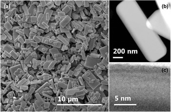
In Fig. 1(a), an overview SEM image of SS-LTO particles is shown. They exhibit a platelet-like rectangular shape with a high in-plane aspect ratio [see Fig. 1(b)] of 2.4 ± 0.5 over 11 particles. Sharp edges indicate a high crystallinity up to the edge of the particle. This is confirmed by HREM imaging as displayed in Fig. 1(c).
LTO particles: (a) SEM overview image (b) HAADF-STEM image of one particle (c) HREM image of a particle edge in [010]-direction.

Highly dispersed particles on the TEM grid were mostly deposited with the shortest particle dimension out-of-plane and the two longer particle axes in-plane of the TEM-grid. Almost all particles lying flat on the TEM grid were electron transparent for 200 kV electrons. Taking this into account and measuring the shortest particle axis on some exceptionally tilted particles in agglomerations (see Fig. S1), we estimated the shortest particle axis to be around 100–200 nm, while the in-plane dimensions range from 0.5 to 2 µm.
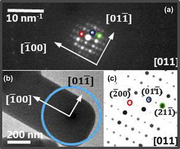
Similar to Wagata et al., Reference Wagata, Zettsu, Yamaguchi, Nishikiori, Yubuta, Oishi and Teshima18 we observed that the LTO-particles were monocrystals. Investigating the SAD patterns of six isolated particles, which were deposited with the shortest particle axis out of plane, we found four times the [011] direction, one time each the [031] and the [010] direction. One example of a SAD pattern in [011] direction, the simulated pattern and the corresponding particle area in image mode is displayed in Fig. 2. All of these orientations have in common that they are closely related to the [010] axis. LTO is part of the perovskite related [110] phases Reference Ebbinghaus, Aguiar, Weidenkaff, Gsell and Reller24 with La and O rich layers parallel to the (010) plane. These layers are dominated by weak bonds and are known as planes for easy cleavage in macroscopic monocrystals, Reference Gasperin22 explaining the short dimension of the out-of-plane particle thickness. In this particular monoclinic structure it is to be expected that the out-of-plane axis observed by SAD is not in all cases the [010], since the angle between the {010} planes and the [010] axis is unequal 90° with a value of 98° (see Fig. 3). The [010] axis can be observed only if the particle is slightly tilted. The same is true for the [031] and the [011] axis orientations. When the [011] axis was observed, the particles were situated at the edges of a hole in the carbon film, explaining the relatively high tilt angle away from the [010] axis. Taking into account the knowledge about cleavage planes in LTO and the experimental evidence collected by SAD, the out-of-plane particle axis was associated with the [010] axis.
(a) SAD pattern in [011] direction from the LTO particle as shown in (b). The blue circle indicates the position of the SAD aperture. (c) shows the simulated electron diffraction pattern in [011] direction.

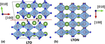
(a) Monoclinic unit cell of LTO with space group P 1 1 21. (b) Orthorhombic unit cell of LTON with space group Imma. Green spheres indicate the La positions, blue spheres the O positions and orange spheres the N positions; the red spheres in the center of the octahedral coordination polyhedron are Ti atom. The red line indicates the cleavage plane parallel to the (010) plane.

Correlating the high aspect ratio of the in-plane particle shape with the crystallographic information obtained by SAD, it was possible to associate in all observed cases the long in-plane axis of the particle with the [100] axis and the short axis with the [001] axis or a related axis, as indicated in Fig. 2(b). These results on LTO coincide with the SAD patterns shown by Wagata et al. Reference Wagata, Zettsu, Yamaguchi, Nishikiori, Yubuta, Oishi and Teshima18 and are summarized in Fig. 6(a) for a typical LTO particle shape.
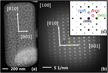
In a similar way SS-LTON platelets were analyzed after thermal ammonolysis, since they are known to be monocrystalline and conserve the shape of the oxide. Reference Wagata, Zettsu, Yamaguchi, Nishikiori, Yubuta, Oishi and Teshima18,Reference Pokrant, Cheynet, Irsen, Maegli and Erni19 This was confirmed by measuring the in-plane aspect ratio, which was found to be similar to SS-LTO with 2.2 ± 0.9 over 11 particles. The SS-LTON platelets showed an out-of-plane axis in [100] direction, a long in-plane axis in [010] direction and a short axis in [001] direction measured over four particles. One example is displayed in Fig. 4. Comparing these findings with the results for LTO, one can conclude that the [001]LTO transformed to [001]LTON, the [100]LTO to [010]LTON and the [010]LTO to [100]LTON, as summarized in Fig. 6.
SS-LTON particle: (a) HAADF-STEM image (b) SAD pattern of the same particle and the simulated diffraction pattern in [100] direction.

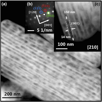
The contrast observed in the HAADF image [Fig. 4(a)] of SS-LTON indicates the presence of pores which seem to be randomly distributed. However, some of the tilted particles, which were not deposited flat on the grid due to particle agglomerations, showed elongated pores with about 14 nm in width and a large range of different length between 100 and 1000 nm [Figs. 5(a), 5(c), and S2]. For some of the cases SAD patterns could be obtained and indexed. They showed hexagonal patterns characteristic for [210] and related directions, revealing orientations mostly in the [210] direction [Fig. 5(b)]. Correlating the SAD pattern of Fig. 5(b) with the STEM-image displayed in Fig. 5(c) the channel side faces are parallel or equal to the (001) plane, while the elongation direction is observed along the [120] axis. The same observation was repeated on other LTON particles (see Fig. S2).
(a) HAADF-STEM image of a SS-LTON particle viewed in [210] direction. Elongated pores with around 14 nm in width, 30-40 nm in spacing and several hundreds of nm are shown. (b) SAD pattern of particle area as displayed in (c). The channel walls are planes parallel to the (001) plane.

However, analyzing Figs. 5(a) and 5(c) more closely, contrast fluctuations within the channels are visible. One interpretation is that elongated pores can be found in directions other than the [210] directions, which form mostly 60° or 120° angles, as outlined in Fig. S3(a). Moreover, it was observed by HREM [Fig. S3(b)] that the pores were faceted and hexagonally shaped indicating that all side facets belonged to the same plane family. These results coincided very well with studies on PC-LTON,
Reference Pokrant, Cheynet, Irsen, Maegli and Erni19
where all observed pores showed likewise a hexagonal shape, when viewed from the [210] direction or from a related one. In the orthorhombic Imma structure, four directions are available in total which give rise to hexagonal plane configurations: the [210], [012],
 $\left[ {0\bar 12} \right]$
, and
 $\left[ {2\bar 10} \right]$
directions, which are perpendicular to the faces of the oxygen/nitrogen coordination octahedron around the central Ti atoms. For illustration the projection of a typically-shaped LTON model particle along the [210] direction built up from unit cells is displayed in Fig. S4. The model particle outline and the thickness increase in
 $\left[ {\bar 120} \right]$
direction throughout the particle correspond very well to the experimentally observed features in Figs. 5(c) and S2, confirming the validity of the model LTON particle shape and projection direction. Therefore, we propose that a complex mesoporous three dimensional network was formed between pores potentially elongated in one of the in-plane directions of the octahedron faces like the [120] direction [Figs. 5(c) and 6(b)] and with pore walls parallel to the (100), (001), (121),
 $\left( {\bar 121} \right)$
,
 $\left( {12\bar 1} \right)$
, or
 $\left( {1\bar 21} \right)$
plane. It is conceivable that this network viewed from the [100] direction looks nonordered or random [Fig. 4(a)].
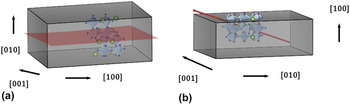
(a) Sketch of a LTO particle shape with crystal directions. The LTO unit cell is depicted in the interior. The red (010) plane indicates the area where the reactive gas can penetrate during ammonolysis. (b) Sketch of a LTON particle with crystalline axis. The red arrow indicates the elongation direction of the pores [120]. Both particles contain the same number of La and Ti atoms. The difference in particle height between LTO and LTON visualizes the volume change caused by the unit cell contraction.

For PC-LTON, it has been shown that the origin of pore formation lies in the reduction of the unit cell volume during the transformation from LTO to LTON by removing the O and La rich plane in the middle of the unit cell (see Figs. 3 and 6). This is the same plane where the reactive gas penetrates into the particle during thermal ammonolysis. Reference Pokrant, Cheynet, Irsen, Maegli and Erni19,Reference Ebbinghaus, Aguiar, Weidenkaff, Gsell and Reller24 This shrinkage of the unit cell does not lead to a reduction of particle size, but to pore formation, because of the limited mobility in SS-gas phase reactions like thermal ammonolyis. Reference Pokrant, Cheynet, Irsen, Maegli and Erni19 We assume that the driving force behind the pore formation in SS-LTON is the same, since the larger particle size of SS-LTO in comparison to PC-LTO is even less likely to promote the reduction of particle size instead of pore formation. From Fig. 3, it becomes apparent that the transformation from LTO to LTON is a complex process where collective translation and replacement of atoms have to occur at the same time as the rotation of the Ti–O octahedron, as indicated by arrows. This could be the explanation, why the pore facets are connected to planes containing the octahedra edges in directions tilted away from the simple (010)LTO or (100)LTON plane, where the reactive gas penetrates and where one could have expected that pores are formed (Fig. 6). The fact that very long channels were observed indicates that large sections of the LTO particles transform collectively.
From an application point of view in photoelectrochemistry or photocatalysis, the most important aspect is the observation of the extremely elongated mesopores, almost channel-like, as shown in Fig. 5(a), which are created during thermal ammonlysis of SS-LTO. By now, SS-LTON already shows the best performance out of several LTON morphologies because of the enhanced surface area due to the presence of mesopores in large single crystals. Reference Landsmann, Maegli, Trottmann, Battaglia, Weidenkaff and Pokrant7,Reference Maegli, Pokrant, Hisatomi, Trottmann, Domen and Weidenkaff15 If they are prolonged even further, a significant enhancement of the active surface area could be obtained by creating a perforated structure almost like a honeycomb. This could be achieved for example by changing the precursor LTO shape, adapting the type and quantity of flux used during synthesis, or by varying the ammonolysis conditions to enhance atom mobility.
IV. CONCLUSION
Monocrystalline particles of SS-LTO exhibited a platelet-like morphology. The particle axes were associated with crystal axes: the [010] as out-of-plane axis, the [100] as the long and the [001] as the short in-plane axis. The particle shape and monocrystallinity were conserved upon transformation of SS-LTO to SS-LTON by thermal ammonolyis. The particle axes of SS-LTON were associated with the [100] direction as out-of-plane axis, the [010] direction as long and the [001] as short in-plane axis. The shrinkage of the unit cell from LTO to LTON is accommodated with the creation of pores. These hexagonally shaped pores are linked to the faces of the oxygen/nitrogen coordination octahedron around the central Ti atoms. In some directions, like the [120] direction, highly elongated pores with several hundred nm in length and 14 nm in width were observed. Although SS-LTON shows already the best performance in photocatalysis and photoelectrochemical applications compared to other morphologies due to increased surface area established by mesopores, a further extension of the elongated pores to a honeycomb like structure has the potential to enhance this effect and lead to even better photoelectrochemical or photocatalytic activity.
Supplementary Material
To view supplementary material for this article, please visit http://dx.doi.org/10.1557/jmr.2016.9.
STEM-image of the shortest (=out-of-plane) axis of the LTO platelets (Fig. S1). LTON particle with elongated pores viewed in [210] direction (Fig. S2). HAADF-STEM image and HREM image of porous region in SS-LTON (Fig. S3). Projection of a monocrystalline LTON particle in [210] direction (Fig. S4). This material is available free of charge via the internet.
ACKNOWLEDGMENTS
The Swiss National Science Foundation (SNSF) is gratefully acknowledged for funding this research within the PrecoR Project 20PC21_155667. The authors thank C. Battaglia for proof-reading of the manuscript.