Introduction
In satellite communications, circularly polarized (CP) antennas are highly demanded due to their several unique advantages, such as ability to overcome the Faraday effect in ionosphere [Reference Checcacci and Spalla1] and polarization distortion elimination [Reference Volakis2]. In particular, dual-CP shared-aperture antenna arrays have received extensive attention because of their compact aperture area and low system costs, which can save valuable space resources of satellite system [Reference Zhang, Yin, Kong, Wang, Zhu, He and Sun3–Reference Xia, Liu, Zhu and Fu6]. Microstrip antenna arrays can be competitive candidate due to their low profile [Reference Liu, Cao, Chen and Yan7–Reference Zhang, Lin, Sun and Yin11]. However, the axial ratio beamwidth (ARBW) of elements is usually limited, which may restrict the scanning coverage. Cavity-backed antennas with wide ARBW were proposed [Reference Yan, Jiao, Cheng and Zhang12, Reference Ji, Dong, Wen and Fan13], while they typically need relatively large horizontal dimensions, making it difficult to meet the element spacing requirement for wide-scanning array. Shorting PINs loaded on the radiating patch can control the beamwidth [Reference Zhang, Zhu and Liu14, Reference Luo, Chu and Zhu15]. Nevertheless, electronic components are normally not recommended for being exposed in the harsh space environment. In addition, poor cross-polarization level (XPL) can be a problem due to the regular arrangement of antenna elements. Rotated technique such as sequentially rotated technique (SRT) [Reference Huang16–Reference Smolders and Johannsen18] is normally adopted to achieve a better scanning performance.
In this paper, a low-profile L-band dual-CP antenna array using spiral sequential rotation (SSR) technique is proposed. Stacked antenna element with wide 3-dB ARBW of 206° is presented to realize right-hand CP (RHCP) for downlink frequency band (1710–1730 MHz) and left-hand CP (LHCP) for uplink frequency band (1800–1820 MHz). Extremely small size of 0.005λ3 is achieved by using the ceramic substrate with high dielectric constant. Furthermore, the SSR technique is applied to achieve low XPL across a large scanning angle. A 6 × 6 array prototype was fabricated and measured for validation. Measured results show that a wide 3-dB AR scanning angle of ± 55° is realized for LHCP as well as RHCP radiation. Additionally, low XPL with gain fluctuation less than 4 dB is achieved over wide-scanning angle of −55° ∼ + 55°. Moreover, the array has successfully passed the mechanical test and the thermal vacuum test (−90° ∼ + 90°). With the dual-CP radiation capability, ultra-low profile of 0.06λ, wide 3-dB AR scanning angle, and low XPL, the proposed dual-CP SSR array is a highly attractive candidate for satellite communication applications.
Antenna design
Antenna structure
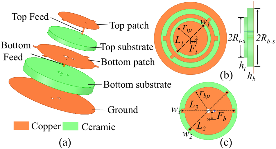
Figure 1 shows the configuration of the proposed L-band dual-CP antenna, which consists of double-layer dielectric, two radiation patches, two feeding probes with a radius of 0.15 mm and a ground plane. And its detailed dimension parameters are shown in the figure caption. As shown in Figure 1, each of the radiation patch consists of a circular radiator with several slender rectangular structures. The upper radiator generates RHCP radiation at higher frequency and the lower radiator generates LHCP radiation, respectively. The substrates chosen for this antenna are ceramic substrates with the dielectric constant of 14 ∼ 16 (upper layer) and 7 ∼ 9 (lower layer), respectively.
(a) Exploded view, and (b) top and side views of the proposed dual-CP element, and (c) top view of bottom patch (rtp = 12.2 mm, rbp = 17.1 mm, Rt-s = 14.6 mm, Rb-s = 21.1 mm, L1 = 28 mm, L2 = 40.8 mm, L3 = 39 mm, w1 = w2 = 2 mm, w3 = 3 mm, Ft = 4.3 mm, Fb = 5.5 mm, ht = 2.5 mm, hb = 4.5 mm).

Working principle
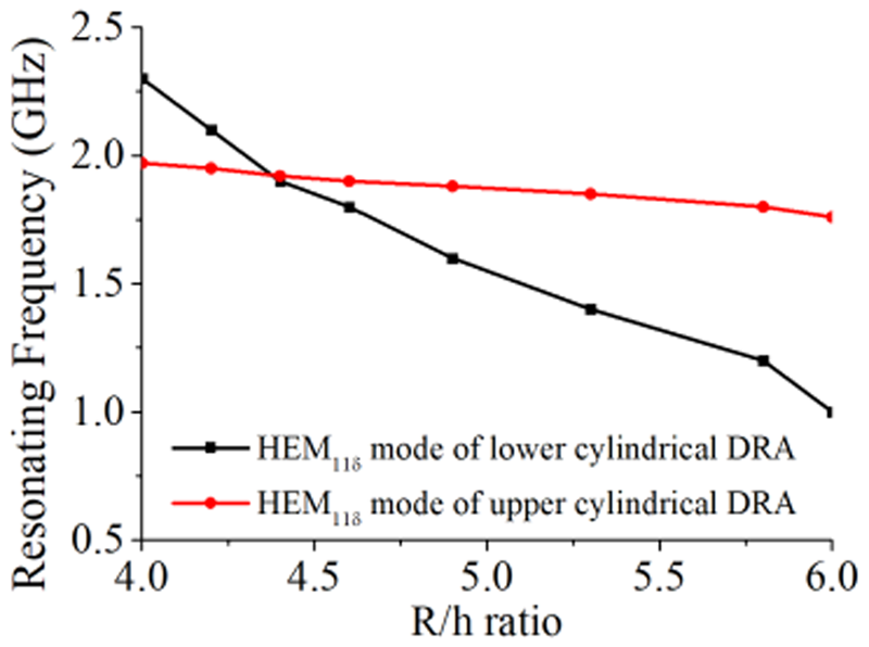
The antenna’s operation is based on a combination of the dielectric resonator antenna (DRA) and the microstrip antenna. The ceramic substrates with high dielectric constant laid on the ground can be taken as a cylindrical DRA working in HEM11δ mode. As Figure 2 illustrates, the resonant frequencies of the cylindrical DRAs decrease as the ratio of R/h increases [Reference Deyoung and Long19], which can be optimized to align the resonant frequency with the desired operating frequency. Figure 3 shows the influence of the circular patch covering the top of the dielectric. On the one hand, it can lower the resonant frequency by acting as a parallel capacitor. On the other hand, the patch itself works as a microstrip radiator and excites the TM01 mode. Therefore, as the patch radius increases, the working frequency of TM01 decreases. As a result, the frequency difference between the HEM11δ and TM01 modes becomes smaller. Consequently, the impedance bandwidth is broadened when the two frequencies are brought close to each other.
Simulated resonant frequencies versus R/h ratio of the bottom and top cylindrical DRAs.

S-parameters versus frequency for different radius of (a) bottom patch and (b) top patch.

Circular polarized properties
The slender rectangular structures on the circular radiator are presented to achieve CP radiation. Characteristic mode analysis (CMA) is employed to explain the operating principle. Figure 4 compares the simulated modal weighting coefficients (MWCs) excited by the feed probes for the configurations without and with the slender rectangular structures. As shown in Figure 4(a) and (c), the bottom feed probe (P1) only excites mode 4 while the top feed probe (P2) only excites mode 5 without the slender rectangular structures. However, with the introduction of the slender rectangular, P1 excites both modes 3 and 4 concurrently, and P2 excites both modes 5 and 6 simultaneously. According to the characteristic-mode theory in [Reference Garbacz20], circular polarization is obtained when two modes have analogous modal significance and phase difference close to 90°. As shown in Figure 5, the current directions of modes 3 and 4 are orthogonal at 1720 MHz, as well as modes 5 and 6 at 1810 MHz, which represents that the CP radiation can be achieved.
MWCs at 1720 MHz excited by P1 (a) without and (b) with slender rectangular structures. MWCs at 1810 MHz excited by P2 (c) without and (d) with slender rectangular structures.

Modal surface currents at (a) 1720 MHz excited by P1 and (b) 1810 MHz excited by P2.

Parameters study
Key parameters are investigated to optimize the impedance matching and the CP performance listed in Table 1. First, as discussed in Section B, the ratio of R/h and radius of patch are critical in determining the operating frequency. Consequently, the inherent resonant frequency of the bottom DRA is 1.81 GHz, and the operating band is 1.71–1.73 GHz when patch radiator covers the dieletric, while the top DRA resonates at 1.93 GHz and has an operating band of 1.80–1.82 GHz with patch radiator covered. Furthermore, the values of Ft and Fb could be adjusted to optimize the impedance matching for a better impedance bandwidth (BW10 dB). Second, the values of L1, L2, and L3, lengths of the slender rectangular structures on the circular radiators, are tuned to improve AR performance. As can be seen in Figure 6, increasing L1, L2, and L3 generally achieves a better AR but has a negligible impact on the impedance property. However, these lengths are constrained by the substrate radius, as the rectangular structures must maintain a sufficient distance from the substrate edge to ensure dimensional accuracy during fabrication. Therefore, L1, L2, and L3 are optimized for a tradeoff between the AR property and processing feasibility.
Effects of different values of L1, L2, and L3 on S-parameters and ARs of (a) bottom element and (b) top element.

Influences and values of the key parameters

Simulated and measured results
To verify the performance of the design, a prototype was fabricated and measured. Figure 7 presents photographs of the prototype and a plot of the simulated and measured gain, AR, and reflection coefficients. The proposed antenna has an extremely small size of 0.005λ3(0.29λ × 0.29λ × 0.06λ), making it particularly suitable as an array element with low inter-element coupling characteristics.
Photograph of fabricated antenna. (a) Top view without and with radome. (b) Back view. (c) Simulated and measured gain and AR. (d) S-parameters.

The measured radiation efficiencies range from 57.6% to 67.2% in the downlink band and from 63.1% to 68.6% in the uplink band. And the measured BW10 dB are 2.9% and 3.3% at downlink and uplink bands, respectively. The isolation between the low-band probe P1 and the high-band probe P2 exceeds 12 dB over the operating band. Owing to the high dielectric constant of ceramic substrate, the 3-dB axial ratio bandwidths are 1.2% and 0.83% at downlink and uplink bands, respectively. The measured gains are above 4.5 dBi, and the gain fluctuation is within 0.6 dB across the entire BW10 dB.
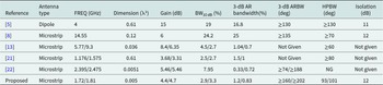
The 3-dB ARBW and radiation patterns are presented in Figure 8. For the down-link band at 1720 MHz, the measured half-power beamwidths (HPBWs) are 98° at φ = 0° plane and 93°at φ = 90° plane, and the corresponding 3-dB ARBW are 160° and 167°, respectively. Similarly, for the up-link band at 1810 MHz, the HPBWs reach 101° at φ = 0° plane and 106° at φ = 90° plane, with 3-dB ARBW extending to 202° and 206°, respectively. Table 2 shows the performance comparison between other dual-CP antennas and the proposed antenna. It can be observed that among the listed designs, the proposed antenna has both the widest 3-dB ARBW and the smallest size.
Simulated and measured radiation patterns at (a) 1720 MHz and (b) 1810 MHz. Simulated and measured results are in a relatively good agreement.

Comparison of the proposed and dual-CP reference antennas

Array implementation and performance
Array configuration
The SSR can overcome the problem of high XPL and high SLL during wide-angle scanning by disrupting the periodic phase distribution [Reference Kang, He, Xiao and Liang23]. In this paper, we composed the array using SSR as shown in Figure 9. The rotation angle is 360°/36. To improve the aperture efficiency, the elements are regularly arranged in a triangular configuration rather than a conventional square way, with an inter-element distance of 0.56λ at the highest resonance frequency of 1820 MHz. Correspondingly, the spacing between the array elements is about 0.52λ at the lowest frequency of 1710 MHz. For comparative analysis, we additionally simulated an SRT array, which was composed of 2 × 2 antenna subarrays with conventional sequential rotation angles of 0°, 90°, 180°, and 270°. Figure 10 shows the compensated phase matrices and as can be seen that there is a large and regular phase oscillation between 0° and 360° for SRT, while the phases of each element are scattering around the array of SSR, which could disrupt the periodic oscillation.
Layout and rotated angles of the 6 × 6spiral sequentially rotated L-band dual-CP microstrip antenna array.

Representation of layout and compensated phase matrices at 1720 and 1810 MHz on (a) the conventional SRT and (b) the SSR.

The RHCP/LHCP arrays demonstrate similar performance characteristics when employing the identical sequential rotation techniques. Taking the RHCP array as an example, the corresponding co-polarized (COP) and cross-polarized (XP) patterns at 1810 MHz are shown in Figure 11. When the antenna array was arranged in a square way, poor XPL at the diagonal-plane (D-plane, defined as φ = 45° plane) was a major issue for SRT [Reference Smith24]. However, the triangular configuration shifts this high XPL region to the H-plane (φ = 90° plane). It is evident from Figure 11(a) and (b) that when the main beam is steered to (θ = 50°,φ = 90°). For the SRT array, the XP pattern exhibits prominent grating lobe in the H-plane with its level almost as high as the main lobe of COP. For the SSR array, the grating lobe in the H-plane has been eliminated while achieving a remarkable 12 dB improvement in cross-polarization suppression (from 4.1 to 16.1 dBc), which verifies the effectiveness of the SSR array to enhance the cross-polarization suppression.
Top views of the full-wave simulated XP and COP patterns when the main beam is steered to (a) θ = 50°, φ = 90°, (b) θ = 50°, φ = 45° by the SRT, and (c) θ = 50°, φ = 90°, (d) θ = 50°, φ = 45° by the SSR at 1810 MHz.

Prototype and experimental result
To verify the simulated results, as shown in Figure 12, a 6 × 6-element low-profile dual-CP antenna array using the SSR technique was fabricated and measured. To evaluate the scanning performance, an RF network, which consists of a 1:36 power divider and 36 phase-shifters, is applied to provide required excitation phase of each element for beam steering after channel calibration. Figure 13 presents the measured S-parameters over operating frequency band. Only the isolations between the central array element (element E1 in Figure 12) and its adjacent elements (E2-E7) are measured, which are all larger than 22 dB. The measured patterns are shown in Figure 14 and summarized in Table 3.
Photograph of (a) fabricated 36-element L-band dual-CP SSR array and (b) measurement scenario.

Measured S-parameters of (a) high-band probes and high-band probes, (b) high-band probes and low-band probes, and (c) low-band probes and low-band probes over working frequency.

Measured and simulated radiation patterns versus beam steering at (a) 1720 MHz and (b) 1810 MHz. Simulated and measured results are in a good agreement.

Comparison of the proposed and reference dual-CP arrays

The SSR can effectively solve the grating lobe problem in H-plane as mentioned before. For the down-link band at 1720 MHz, the measured XPLs at E-plane (φ = 0°), H-plane (φ = 90°), and D-plane (φ = 45°) are −19.8, −22.4, and −18.7 dB, respectively. Moreover, for the up-link band at 1810 MHz, the measured XPLs at E-plane, H-plane, and D-plane are −18.1, −19.6, and −19.2 dB, respectively. The simulated and measured axial ratio and boresight gain versus beam steering are presented in Figure 15, while Figure 16 shows the cross-polarization suppression and radiation efficiency versus frequency. The proposed array can maintain the boresight gain fluctuation within 1.6 dB over the operating frequency band and the scan loss at θ = 55° is less than 4 dB. For the low-band probe, the measured gain is between 17.46 and 18.64 dB, with cross-polarization suppression between 23.2 and 28.8 dBc. Meanwhile, for the high-band probe, the corresponding values are 18.4–19.03 dB for gain and 24.7–31.2 dBc for suppression. Additionally, its 3-dB AR scanning angle was from −55° to +55° over the operational band, which has a good CP wide-angle scanning characteristic. Furthermore, the measured radiation efficiencies during beamforming are 52.2%–59.3% in the downlink and 56.6%–64.1% in the uplink bands, which are slightly lower than that of a single antenna due to the coupling losses.
Simulated and measured (a) axial ratio and (b) boresight gain versus beam steering.

Co-/cross-polarization gain (dBi) and radiation efficiency versus frequency over (a) downlink band and (b) uplink band.

Finally, a comparison between our work and previous dual-CP for wide-scanning works is provided in Table 3. In contrast, our proposed array has the lowest profile as well as XPL over the 3-dB scanning angle. All the merits make our proposed dual-CP array an attractive candidate for the wide-angle coverage satellite system. However, as these systems typically employ frequency-division duplexing and the third-order inter-modulation product falls close to the received band, it is recommended to use transceiver filters connected after the antenna to suppress interference effectively.
Conclusion
A low-profile dual-CP antenna array using the SSR technique is proposed for satellite communication in this work. The array element consists of two stacked CP patches and double-layer ceramic substrate with high dielectric constant. Dual CP radiations are accomplished by the slender rectangular structures on the radiators, which can excite two orthogonal characteristic modes. Moreover, extremely small size of 0.005λ3 and wide 3-dB ARBW of 206° are achieved. Furthermore, a prototype of a 6 × 6 SSR array was fabricated and measured. Measured results show that a wide 3-dB AR scanning angle of ± 55° is realized for LHCP as well as RHCP radiation. Additionally, low XPL less than −18.1 dB with gain fluctuation less than 4 dB are achieved over −55° ∼ + 55°. All the merits of dual-CP radiation, ultra-low profile, wide 3-dB AR scanning angle, and low XPL make our proposed dual-CP SSR array be highly attractive candidate for satellite communication applications.
Acknowledgements
The authors declare no competing interests.
Funding
This work was supported by the CAS Key Technology Talent Program under Grant E0293006.

Zhanyu Kang is with the Innovation Academy for Microsatellites, Chinese Academy of Sciences (IAMCAS), Shanghai 201304, China, and also with the University of Chinese Academy of Sciences (UCAS), Beijing 100049, China (e-mail: bbppshiwo@126.com).

Lianxing He is with the Innovation Academy for Microsatellites, Chinese Academy of Sciences (IAMCAS), Shanghai 201304, China (e-mail: 13816474811@139.com).

Dongliang Fei is with the Innovation Academy for Microsatellites, Chinese Academy of Sciences (IAMCAS), Shanghai 201304, China (e-mail: feidl@microsate.com).

Guang Liang is with the Innovation Academy for Microsatellites, Chinese Academy of Sciences (IAMCAS), Shanghai 201304, China (e-mail: hnlg219@163.com).

Shaokang Pan is with the School of Information Science and Technology, ShanghaiTech University, Shanghai 201210, China, and also with the Innovation Academy for Microsatellites, Chinese Academy of Sciences (IAMCAS), Shanghai 201304, China. (e-mail: panshk@shanghaitech.edu.cn).