Nomenclature
- EI
Emission index
- EI(CO)
Emission index of CO
- EI(NOx)
Emission index of NOx
- LBO
Lean blowout
- PIV
Particle image velocimetry
Symbols
-
 ${\bar T_c}$
average temperature at multi-point thermocouple
-
$\phi$
equivalence ratio
- T d
temperature at dump plane


1. Introduction
Owing to emerging environmental problems caused by exhaust gases, regulations on exhaust gas (such as NOx and CO) emissions are being applied across various industries, and these regulations are becoming increasingly stringent. In the field of gas turbines, which are widely used in power generation and aviation propulsion, strict emission regulations are being imposed [Reference Lee, Fahey, Forster, Newton, Wit, Lim, Owen and Sausen1, Reference Liu, Sun, Sethi, Nalianda, Li and Wang2]. Among emission gases, NOx emission is mostly prominent in gas turbines. Therefore, the development of low-NOx combustors is crucial for satisfying the regulations.
In gas turbines operated via burning fuel, most of the generated NOx is thermal NOx formed in high-temperature and post-flame regions [Reference Lefebvre and Ballal3]. In high-temperature regions, nitrogen and oxygen molecules are segregated into atomic units, and NOx is formed via the Zeldovich mechanism [Reference Turns4, Reference Dagaut, Glarborg and Alzueta5]. Because these reactions are endothermic processes, the NOx formation are accelerated as the temperature increases. To fully understand mechanisms of emissions and reduce emissions, emission characteristics have been investigated extensively for development of low-NOx combustors.
Joo et al. analysed the effect of hydrogen content in fuel on the emission characteristics of a syngas-fueled single-nozzle partially premixed combustor. According to them, as the hydrogen content in fuel increased, NOx emission increased owing to the higher flame temperature [Reference Joo, Kwak and Yoon6]. Bulat et al. conducted large eddy simulations on NO and CO formation in an industrial gas turbine combustor. The mechanisms of NO and CO formation were analysed with respect to the flame and temperature distribution inside the combustor [Reference Bulat, Jones and Marquis7]. In addition to the abovementioned studies, several experimental [Reference Yin and Gangoli Rao8, Reference Han, Kim, Kim and Jeon9] and numerical [Reference Andreini, Facchini, Innocenti and Cerutti10, Reference Farokhipour, Hamidpour and Amani11] studies analysing emission characteristics have been conducted.
The most widely used strategy for reducing NOx emissions is a lean premixed combustion, where premixed fuel and air are burned under fuel-lean conditions near the lean blowout (LBO) limit to achieve flame temperatures that are lower than those achieved under stoichiometric condition. Therefore, the LBO limit is a crucial parameter in developing low-NOx combustors, and changes of the LBO limit with respect to various parameters such as fuel [Reference Xiao and Huang12, Reference Muthuselvan, Suryanarayana Rao, Iyengar, Pulumathi, Thirumalachari and Srinivasan13] and combustor geometry [Reference Wang, Zhang, Hui, Lin and Li14] have been investigated extensively.
However, because the analyses performed in most studies pertain to combustors with one nozzle, the emission characteristics of real gas turbines, which have multiple nozzles, are difficult to fully comprehend those mechanisms. Typically, in real gas turbines, multiple nozzles are installed in the same combustion chamber; therefore, the interaction between flames from each nozzle is inevitable. Interacting flames, in which several flames interact with each other, exhibit different combustion characteristics as compared to the single flames [Reference Lee, Park, Han and Kim15, Reference Chen, Culler, Peluso, Santavicca and O’Connor16]. Therefore, the emission and LBO limit characteristics in multi-nozzle combustors must be investigated.
Cho et al. performed numerical simulations pertaining to the change in NOx emission based on the distance between two nozzles in a swirl-stabilised combustor with two nozzles. They reported that the distance between the nozzles can significantly affect NOx emissions, as discussed based on the change in temperature distribution inside the combustor with respect to the distance between nozzles [Reference Cho, Sohn, Cho and Kim17]. Dolan et al. experimentally observed that the change in NOx emissions with respect to the distance between the nozzles contributed primarily to the change in flame distribution, which induced a change in NOx emission [Reference Dolan, Gomez, Zink, Pack and Gutmark18]. Kwong et al. experimentally measured the change in the LBO limit at various distances between nozzles. They showed that the change in the flow field due to the change in the distance between nozzles significantly affected the LBO characteristics [Reference Kwong and Steinberg19]. Although several studies pertaining to multi-nozzle combustors have been conducted, the detailed mechanisms of emission and LBO characteristics in multi-nozzle combustors are yet to be elucidated. Therefore, in this study, comparisons of emission characteristics and LBO limit between single- and dual-nozzle combustors were conducted to reveal the effect of flame-flame interaction. A more comprehensive understanding on the effects of the flame-flame interaction will facilitate the development of low-NOx combustors.
2. Experimental methods
2.1 Gas turbine combustors and instruments
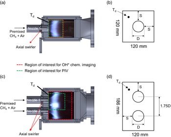
Experiments were performed in both single- and dual-nozzle combustors, and detailed views of the combustion chamber are shown in Figs. 1(a) and 1(c). Room-temperature (∼20°C) air and gaseous methane were used as the oxidiser and fuel, respectively. Perfectly premixed fuel and air were supplied through an axial swirling nozzle. The swirling nozzle comprised six swirl vanes inclined at 45°. The swirl number of the nozzle was approximately 0.8, and the nozzles were located at 45mm upstream of the dump plane. Downstream of the dump plane, a 200mm-long quartz plate was equipped to visualise flames, and the quartz plate was cooled with high-pressure air jets to prevent thermal damage caused by the high temperature of the flames.
Detailed views of the combustion chamber and its cross-section: (a) and (b) for the single-nozzle combustor and (c) and (d) for the dual-nozzle combustor (Td: thermocouple at the dump plane, D: nozzle diameter, and S: distance between nozzle edge and combustor wall).

OH* chemiluminescence imaging and particle image velocimetry (PIV) measurements were performed to observe the characteristics of the flame structure and the flow field inside the combustion chamber. For the OH* chemiluminescence imaging, an intensified CMOS camera (LaVision, HighSpeedStar 8 with HighSpeed-Intensified Relay Optics), a Cerco UV lens (f = 100mm, f/2.8), and a bandpass filter (320
 ${\rm{ \pm }}$
20nm) were used. For the PIV measurement, a CMOS camera (LaVision, HighSpeedStar 8) with a lens (f = 50mm, f/1.4) and a band-pass filter (527
 ${\rm{ \pm }}$
5nm) and a dual-cavity Nd:YLF laser (Photonics, DM20-527, 1.7mJ/pulse at 527nm) were employed. TiO2 particles with a nominal diameter of 5μm were used as seeding particles. The particles were seeded into the air supply line at far upstream of the dump plane, maintaining a constant total air flow rate. Pairs of two images for vector calculation were captured at 25μs intervals. The velocity vectors were calculated using a fast Fourier transform-based cross-correlation analysis with an interrogation window of 32 × 32 pixel2.
The region of interest for both OH* chemiluminescence imaging and PIV are also shown in Figs. 1(a) and 1(c). The region of interests for the former were set to the entire area of the quartz plate (120 × 120mm2 for the single-nozzle combustor and 186 × 120mm2 for the dual-nozzle combustor) in both combustors. The region of interest for PIV was the same as that for OH* chemiluminescence imaging in the single-nozzle combustor. However, in the dual-nozzle combustor, the region of interest for PIV was reduced to the upper region of the quartz tube (120 × 120mm2) to obtain an appropriate signal-to-noise ratio of the Mie scattering signal from the particles.
The combustion chamber of both combustors had a rectangular cross section, and the nozzle diameter in both combustors was the same, i.e. 42.6mm. Figures 1(b) and 1(d) present the cross-sectional shape of each combustor. The single-nozzle combustor had a square cross section measuring 120 × 120mm2, and the dual-nozzle combustor had a rectangle cross section measuring 186 × 120mm2, in which the cross section of the single-nozzle combustor was stretched in the vertical direction. In the dual-nozzle combustor, the distance between the nozzle and combustor wall (S
 $\approx$
0.9D) was maintained constant as the distance at the single-nozzle combustor because the distance between the nozzle and combustor wall is a crucial factor determining combustion characteristics (such as the flammable region and combustion dynamics) [Reference De Rosa, Peluso, Quay and Santavicca20]. In addition, the distance between the two nozzles was set to be approximately 1.75 times of the nozzle diameter to ensure appropriate interactions between the flames from the two nozzles.
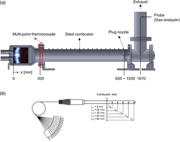
A detailed view of the downstream region of the combustion chamber is shown in Fig. 2(a). The combustion chamber of both the single- and dual-nozzle combustors were connected to the same circular water-cooled steel combustor, which had an inner diameter of 130 mm. At the end of the steel combustor, a movable plug nozzle was installed. Using the plug nozzle, the combustor length can be varied from 600 to 1,500mm.
Detailed views of (a) downstream of the combustion chamber and (b) the multi-point thermocouple.

The temperature was measured at two locations: at the dump plane and 300mm downstream of the dump plane. A K-type thermocouple was installed at the dump plane to measure the temperature at the dump plane (T d). Measurement ports of Td in the combustors are presented in Figs. 1(b) and 1(d), where the port in the single-nozzle combustor was located at 40mm side and 55mm above from the nozzle centre, and the port in the dual-nozzle combustor was located at 35mm side and 20mm above from the centre of the upper nozzle. The tip of the thermocouple was located 10mm upstream of the dump plane. At 300mm downstream of the dump plane, where the rectangular combustion chamber and circular steel combustor were connected, a multi-point thermocouple was installed to measure the temperature distribution in the radial direction. The multi-point thermocouple comprises five K-type thermocouples, and the installation positions are shown in Fig. 2(b). Only a 65mm rod containing thermocouples was exposed from the combustor wall (combustor liner) to the centre of the combustor, and the temperature was measured at five points at intervals of 15mm from the centre. The K-type thermocouples can measure up to approximately 1,370°C with an uncertainty of ±1°C and a resolution of 0.1°C. The temperatures were measured using a data acquisition system (NI 9211) with a repetition rate of 10Hz.
After burning fuels in the combustion chamber, flue gases were discharged through a chimney behind the plug nozzle. A stainless-steel probe for measuring the concentrations of NOx, CO, and O2 was installed at the chimney to ensure that chemical equilibrium was achieved. Before the exhaust gas entered the gas analyser (TESTO, model 350K), it was filtered and dried to eliminate impurities and water vapour. The measurable area and resolution of the gas analyser for various species were as follows; NO: 0–4000 parts per million by volume (ppmv)/0.1 ppmv (0–300ppmv), 1ppmv (>300ppmv), NO2: 0–500ppmv/0.1ppmv, CO: 0–10000ppmv/1ppmv, and O2: 0%–25%/0.01%. In addition, the gas analyser had an uncertainty for emission gases; NO: ±5ppmv, NO2: ±5ppmv, CO: ±10ppmv, and O2: ±0.8% in our measuring region (NO < 100ppmv, NO2 < 100ppmv, CO < 200ppmv, and O2 < 25%). The measured concentrations of NOx and CO can be measured differently based on the operating environment. Therefore, the measured NOx and CO were corrected to values under 15% O2 to compare the emission gas concentration with the same standard in various combustion systems [Reference ElKady, Evulet, Brand, Ursin and Lynghjem21, Reference Baukal and Eleazer22]. All NOx and CO concentrations presented herein are corrected concentrations, and the equation used for correcting the emission gas concentration is presented in Equation (1).
 \begin{align}{\left( {{\rm{N}}{{\rm{O}}_{\rm{x}}},{\rm{\;CO}}} \right)_{@\;15\% \;{{\rm{O}}_2}}} = {\left( {{\rm{N}}{{\rm{O}}_{\rm{x}}},{\rm{\;CO}}} \right)_{{\rm{measured}}}} \times \frac{{\left( {20.95 - 15\;} \right)}}{{\left( {20.95 - {{\rm{O}}_2}_{{\rm{measured}}}} \right)}}\end{align}
where
 ${{\rm{(N}}{{\rm{O}}_{\rm{x}}}{\rm{,\;CO)}}_{{\rm{@\;15\% \;}}{{\rm{O}}_{\rm{2}}}}}$
corresponds to the corrected concentration to 15% O2, (NOx, CO)measured the measured concentration, and
 ${{\rm{O}}_{\rm{2}}}_{{\rm{measured}}}$
means measured O2 concentration on a dry basis.
2.2 Experimental conditions
Air and methane were controlled using mass flow controllers (Bronkhorst F-206BI with an uncertainty of
 ${\rm{ \pm }}$
0.8% for air, and Bronkhorst Mass-stream D-6361A with an uncertainty of
 ${\rm{ \pm }}$
1% for fuel). The experiments for the dual-nozzle combustor were conducted under three heat load conditions (40, 50, and 60kW), and the heat loads were calculated based on the lower heating value of methane (35.82MJ/Nm3). In each heat load condition, the equivalence ratio (
 $\phi$
) was varied from the LBO limit to the stoichiometric condition (
 $\phi$
= 1.0). We changed
 $\phi$
at intervals of 0.02 to observe distinct differences on flame structure and emissions in each
 $\phi$
because used mass flow controllers had some uncertainties. In the single-nozzle combustor, experiments were performed under half heat load conditions as compared with the dual-nozzle combustor to maintain a constant exit velocity of the nozzle in both combustors; this is because NOx emission is highly affected by the residence time, which correlates with the exit velocity at the nozzle [Reference Hsieh, Dahm and Driscoll23].
Under all experimental conditions, the emission gas and temperature were measured in a dynamically stable state, where the amplitude of dynamic pressure inside the combustor was lower than 0.1% of the static pressure inside the combustor. In addition, the emission gas concentrations and temperatures were measured after approximately 30s after changing flow rates, which had elapsed under condition to ensure a steady state. The experimental conditions are listed in Table 1.
Experimental conditions

3. Results and discussion
The effect of flame-flame interaction on the LBO limit was determined before analysing its effect on the emission characteristics, because most low-NOx combustors are operated near the LBO limit. Therefore, analyses of the LBO limit are presented in the first subsection of this section, and details regarding the emission characteristics are presented in the latter subsection.
3.1 LBO limit
Herein, the LBO limit is defined as
 $\phi$
, at which the flame is extinguished. In gas turbine combustors, low-frequency instability due to the repeated blowout and reattachment of flames typically occurs near the LBO limit [Reference Dhanuka, Temme and Driscoll24]. In our combustors, low-frequency instability at approximately 70Hz also occurred near the LBO limit and disappeared at a certain
 $\phi$
when the
 $\phi$
increased. Therefore, we defined
 $\phi$
as the stable limit where the instability disappeared. In addition, premixed flames can sustain in the region where the flow velocity and flame speed are equal [Reference Turns4]. Therefore, we analysed the changes in the LBO according to the heat load conditions and combustor type based on the relationship between the injection flow velocity at the nozzle exit and flame speed.
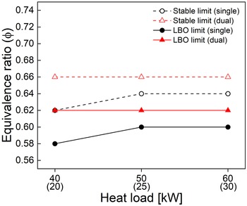
Figure 3 shows LBO and stable limits under various heat load conditions in the single- and dual-nozzle combustors. The limits of the single- and dual-nozzle combustors are indicated in black and red, respectively, and the LBO and stable limits are shown as solid and dashed lines, respectively. In both combustors, the
 $\phi$
at the LBO limit was lower than that of the stable limit. In terms of the LBO limit, as the heat load increased, the LBO limit increased to a high
 $\phi$
or remained constant. Under high heat load conditions,
 $\phi$
at the LBO limit increases owing to the higher flow velocity compared to the low heat load conditions because a higher flame speed is needed for sustaining the flame. However, in this study, the difference in the LBO limit due to the change in the heat load was not shown clearly because the change of the flame speed is large under low
 $\phi$
conditions [Reference Chong and Hochgreb25] and we changed the
 $\phi$
condition at 0.02 intervals, which was a considerably large interval for observing differences in LBO limits. In addition, the fact that the flame speed increase caused by increase in Reynold number in high heat load conditions [Reference Morones, Ravi, Plichta, Petersen, Donohoe, Heufer, Curran, Güthe and Wind26] was contributed to no distinct change of LBO limit with respect to increase of heat input.
LBO and stable limits with respect to heat load condition in the single- and dual-nozzle combustors (in x-axis, number in parentheses indicates the heat load of the single-nozzle combustor).

A comparison of LBO limits between the combustors confirmed that LBO limits of the single-nozzle combustor were lower than those of the dual-nozzle combustor. To determine the reason for this difference in the LBO limit between the two combustors, flow-field measurements were performed at
 $\phi$
= 0.68, in which a stable flame was formed in both combustors. Only the measured flow fields at the heat inputs of 50kW in the dual-nozzle combustor and 25kW in the single-nozzle combustor are presented because the flow fields exhibited similar trends for the three heat load conditions.
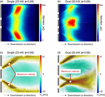
Figure 4 shows the average OH* chemiluminescence images and flow fields for both combustors. In the single-nozzle combustor, a diverging main flow was formed from the dump plane, and a flame was formed downstream of the main flow. Furthermore, a backflow region was formed in a central region due to a recirculation zone. These features are typical characteristics of swirl-stabilised combustors with a single nozzle, as demonstrated in previous studies [Reference Joo, Kwak, Kim, Lee and Yoon27–Reference Fanaca, Alemela, Hirsch and Sattelmayer29]. In addition, the flame structure and flow field of the dual-nozzle combustor are different from those of the single-nozzle combustor, as shown in Figs. 4(b) and 4(d). The flame in the dual-nozzle combustor exhibited its maximum chemiluminescence intensity in the region where the two flames interacted. In addition, in this interaction region, a region with a higher axial velocity than that in the main flow region in the single-nozzle combustor was formed because of the merged flow from the two nozzles. The maximum velocities at the single- and dual-nozzle combustors were approximately 15.2m/s and 21.7m/s, respectively, and the maximum velocity points at both combustors are marked as a red hollow circle in Figs. 4(c) and 4(d). Therefore, it was more difficult to stabilise the flame in the dual-nozzle combustor than in the single-nozzle combustor owing to the region of a higher velocity in the interacting region, where the two main flows from the nozzles collide. Hence, the LBO limits in the dual-nozzle combustor are higher than those in the single-nozzle combustor, as shown in Fig. 3. The emission characteristics of the two combustors are compared in the following sections. If the flame is not well-stabilised, the emission characteristics may be biased. Therefore, the emission measurements were conducted in stable states under higher
 $\phi$
conditions than the stable limits.
Average OH* chemiluminescence images and flow fields at
 $\phi$
= 0.68: (a) and (c) for the single-nozzle combustor at 25kW and (b) and (d) for the dual-nozzle combustor at 50kW (red hollow circles in the average flow field correspond to the maximum velocity point).

3.2 Temperature and emission characteristics
In this section, the emission characteristics (particularly for NOx) of the single- and dual-nozzle combustors are analysed. The measurements were conducted under various
 $\phi$
conditions by changing the air flow rate for each heat load condition. As mentioned above, most of the NOx generated in gas turbine combustors corresponds to thermal NOx generated via the Zeldovich mechanism in the high-temperature region. Hence, the temperature is an important parameter when analysing NOx emission characteristics.
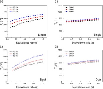
The changes in T
d and combustor temperature (
 ${\bar T_c}$
) under various
 $\phi$
conditions are presented in Fig. 5. The temperatures of the single- and dual-nozzle combustors are presented as filled and hollow circles, respectively.
 ${\bar T_c}$
was the average value of five measured temperatures using the multipoint thermocouple located at 300 mm downstream of the dump plane.
 ${\bar T_c}$
was regarded as an indirectly measured temperature of flame because the measurement location of
 ${\bar T_c}$
was the nearest location to the flame in our configuration. In both combustors, T
d and
 ${\bar T_c}$
gradually increased at each heat load condition as the
 $\phi$
increased, and the temperatures reached their maximum values under stoichiometric conditions (
 $\phi$
= 1.0). This was because of the increase in the adiabatic flame temperature with an increase in
 $\phi$
. In addition, because the flame shifted gradually to the dump plane under high
 $\phi$
conditions owing to the higher flame speed and lower injection velocity at the nozzle than under low
 $\phi$
conditions, the increase in T
d was larger than that of
 ${\bar T_c}$
. Under the same
 $\phi$
conditions, T
d and
 ${\bar T_c}$
increased as the heat load increased in both combustors. This was caused by the heat transfer between the combustor and the environment. Ideally, if the combustor is completely insulated from the environment, the measured temperature will be the same. However, in an actual combustor, heat loss to the environment occurs naturally through the quartz plate and the combustor wall. Therefore, the temperature rise as the heat load increased under the same
 $\phi$
conditions because cooling air and water were supplied at a constant flow rate throughout the entire measurement despite the increases in the heat load.
Td and combustor temperature (
 ${\bar T_c}$
) values with respect to
 $\phi$
in the single and dual-nozzle combustors: (a) and (b) for the single-nozzle combustor and (c) and (d) for dual-nozzle combustor.

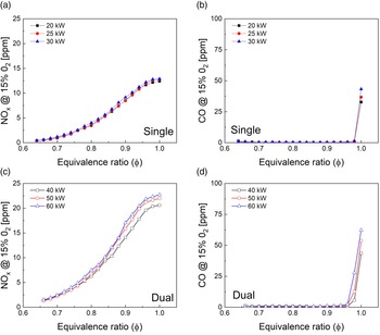
Figure 6 shows changes in the NOx and CO concentrations under various
 $\phi$
conditions. In both single- and dual-nozzle combustors, the NOx concentrations increased exponentially as
 $\phi$
increased. Because T
d and
 ${\bar T_c}$
increased monotonically as
 $\phi$
increased, as shown in Fig. 5, it can be determined that the NOx concentrations were exponentially proportional to the flame temperature (T
d and
 ${\bar T_c}$
). This relationship between flame temperature and NOx concentrations has been confirmed in several previous studies [Reference Williams, Shaddix and Schefer30, Reference Liu, Tan, Gao, Wang and Wan31]. In terms of the CO concentration, CO rarely formed under
 $\phi$
conditions lower than the stoichiometric condition; however, it increased rapidly near the stoichiometric condition. Typically, CO is produced when combustion reactions are not fully completed, either owing to low mixing or a low amount of excess oxygen [Reference Turns4]. Therefore, the CO concentration increased rapidly owing to low amounts of excess air near the stoichiometric condition.
Changes in NOx and CO concentrations at 15% O2 with respect to
 $\phi$
: (a) and (b) for the single-nozzle combustor and (c) and (d) for the dual-nozzle combustor.

In addition, both NOx and CO concentrations in the dual-nozzle combustor were higher than those in the single-nozzle combustor, based on a comparison of the emission gas concentrations between the two combustors. The flame-flame interaction in the dual-nozzle combustor may cause these differences between the combustors because the other primary conditions (
 $\phi$
, exit velocity, and distance between the nozzle and wall) were maintained constant at the two combustors. Similar effects of the flame-flame interaction on the emission characteristics have been demonstrated in the previous studies [Reference Cho, Sohn, Cho and Kim17, Reference Dolan, Gomez, Zink, Pack and Gutmark18]. However, detailed reasons for the large amount of emissions in the dual-nozzle combustor compared with those in the single-nozzle combustor were not addressed in those studies. Therefore, in the next section, we elucidate the effect of flame-flame interaction on the emission characteristics of the dual-nozzle combustor.
3.3 Effects of flame-flame interaction on emission characteristics
The emissions under heat load conditions of 40, 50, and 60kW in the dual-nozzle combustor were compared with those under heat load conditions of 20, 25, and 30kW in the single-nozzle combustor. We converted emission concentration to an emission index (EI) because different amounts of fuel were burned between two combustors. The EI, which is a conventional index defined by the total amount of emission gas produced (in grams) when 1kg of fuel is burned, is used for comparison [Reference Driscoll, Chen and Yoon32]. EI was calculated using Equation (2), as follows:
 \begin{align}{\rm{EI}}\left( {{\rm{N}}{{\rm{O}}_{\rm{x}}},{\rm{\;CO}}} \right) = \;0.001\left( {\frac{{{\rm{M}}{{\rm{W}}_{{\rm{N}}{{\rm{O}}_{\rm{x}}},{\rm{\;\;CO}}}}}}{{{\rm{M}}{{\rm{W}}_{{\rm{C}}{{\rm{H}}_4}}}}}} \right) \times {X_{{\rm{N}}{{\rm{O}}_{\rm{x}}},{\rm{\;\;CO}}}} \times \frac{1}{2}\left( {1 + \frac{{4.76}}{\phi }} \right)\end{align}
where, MWs are the molecular weights of the emitted gas or fuel; X is the concentration of the emitted gas, and
 $\phi$
is the corresponding equivalence ratio. Next, we compare the EI of NOx (EI(NOx)) and that of CO (EI(CO)) between the two combustors.
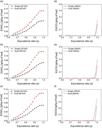
Figure 7 presents the changes in EI(NOx) and EI(CO) under three heat load conditions. The increase in EI(NOx) with respect to an increase in
 $\phi$
was consistent with the results for NOx emissions, as shown in Fig. 6. In addition, the EI(NOx) of the dual-nozzle combustor was higher than that of the single-nozzle combustor under all the
 $\phi$
conditions. Because the exit velocity at the nozzle was maintained in the two combustors and there was a significant difference between the two combustors despite small changes in
 ${\bar T_c}$
(as shown in Fig. 5), the differences in EI(NOx) shown in Fig. 7 can be considered to be caused by the interaction between the two flames in the dual-nozzle combustor.
Comparisons of EI(NOx) and EI(CO) at three heat load conditions between single- and dual-nozzle combustors: (a)-(c) for EI(NOx) and (d)-(f) for EI(CO).

The EI(CO) for both combustors showed low values under most
 $\phi$
conditions except near the stoichiometric condition similar to the results shown Fig. 6. In
 $\phi$
conditions near the stoichiometric condition, CO2 in the combustion product can be dissociated into CO through the water-gas shift reaction (CO + H2O ↔ CO2 + H2) in high-temperature environment. The dissociation of CO2 accelerates as the temperature increases because the reaction is exothermic. Therefore, the CO emissions in the dual-nozzle combustor were larger than those in the single-nozzle combustors only near the stoichiometric condition as shown in Figs. 7(d)-7(f). However, CO emissions were very low under most
 $\phi$
conditions except for some
 $\phi$
conditions near the stoichiometric condition and even in a few
 $\phi$
conditions where CO was discharged. It was insufficient to confirm the effect of flame-flame interaction on CO emissions. Therefore, we did not conduct further analyses on CO emissions.
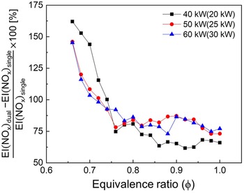
Based on the results shown in Figs. 7(a)-7(c), the increase ratio of EI(NOx) in the dual-nozzle combustor was calculated and the results are shown in Fig. 8. Under all
 $\phi$
conditions, the increase ratio is higher than 50% and it implies that NOx concentrations at the dual-nozzle combustor are much higher than those at the singe-nozzle combustor, when the same amount of fuel is burned. Additionally, the difference in EI(NOx) between the two combustors is larger under high
 $\phi$
conditions (shown in Fig. 7); however, the increase ratios under high
 $\phi$
conditions is smaller than those under low
 $\phi$
conditions.
Increase ratio of EI(NOx) between the single- and dual-nozzle combustors.

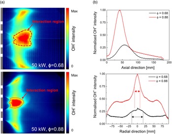
The flame and temperature distributions at downstream of the flame were investigated to elucidate the effect of the flame-flame interaction on the NOx emission characteristics. Flames at the heat load of 50kW were investigated; notably, flames under other heat load conditions showed similar changes. Furthermore, 0.68 and 0.88 were selected as representative examples of high and low
 $\phi$
conditions, respectively. The average flame images (Fig. 9(a)) and the axial and radial distributions (Fig. 9(b)) under these two
 $\phi$
conditions are shown in Fig. 9. The OH* chemiluminescence intensity under these two
 $\phi$
conditions was integrated into the axial and radial directions; subsequently, the integrated profiles were normalised to the maximum intensity.
(a) Average OH* chemiluminescence images at
 $\phi$
= 0.68 (black) and 0.88 (red) in the dual-nozzle combustor and (b) normalised OH* chemiluminescence intensity distribution in the axial and radial direction.

As shown in Fig. 9(a), a high-intensity flame-interacting region between two flames appeared in the middle of the combustor. To clearly depict this high-intensity region, which was defined as a region with an intensity higher than 70% of its maximum intensity, the boundary of the interacting region is delineated with a dashed red line. According to a previous study, the OH* chemiluminescence intensity is proportional to the heat release rate in premixed flames [Reference Lee and Santavicca33]. Therefore, the high-intensity region induced a local high-temperature region, which resulted in higher NOx emissions at the dual-nozzle combustor compared to those at the single-nozzle combustor.
Additionally, we compared the axial and radial flame distributions of the two flames at
 $\phi$
= 0.68 and 0.88 in the dual-nozzle combustor as shown in Fig. 9(b). In the axial direction, the flame at
 $\phi$
= 0.88 exhibits a more compact distribution near the dump plane as compared with the flame at
 $\phi$
= 0.68. This was caused by the increased flame speed and low velocity due to the increase in
 $\phi$
. The same difference is observed in the axial distribution, as shown in Fig. 9(a). In the radial direction, a high-intensity flame-interacting region is observed, showing a high chemiluminescence intensity compared with the other radial locations. The width of the interacting region is indicated by arrows with dotted lines in Fig. 9(b). The flame at
 $\phi$
= 0.68 exhibits a wider interacting region compared with the flame at
 $\phi$
= 0.88.
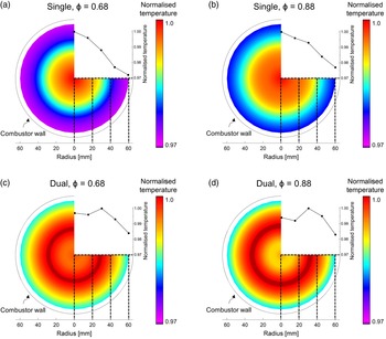
The temperature distributions were compared to determine the difference in the increase ratio of EI(NOx) based on the difference in the width of the interacting region. Two-dimensional (2D) temperature distributions were reconstructed based on five temperatures measured at the multipoint thermocouple, which was located at 300mm downstream of the dump plane. To reconstruct the temperature distributions, it was assumed that the temperature distribution was axisymmetric. Although not presented herein, it was confirmed that the five measured temperatures at different installation angles of the multipoint thermocouple exhibited the same tendency. All temperatures presented herein are normalised with those maximum temperatures.
The reconstructed temperature distributions at
 $\phi$
= 0.68 and 0.88 in both single- and dual-nozzle combustors are depicted in Fig. 10. The five measured temperatures used for reconstruction are shown in the first quadrant of the pie graphs, representing the temperature distribution in radial direction. The distributions for the single-nozzle combustor (Figs. 10(a) and 10(b)) show the maximum temperature at the centre of the combustor and the temperature decreases toward the combustor wall. However, for the dual-nozzle combustor (Figs. 10(c) and 10(d)), the high-temperature region is relatively wider than that of the single-nozzle combustor, and the maximum intensity is detected in the region with a radius of approximately 30mm. This wider high-temperature region in the dual-nozzle combustor contributes to the difference in the NOx concentration in the dual-nozzle combustor. In other words, the flame-flame interaction widened the high-temperature region at downstream of the flame, resulting in a higher EI(NOx) of the dual-nozzle combustor as compared with that of the single-nozzle combustor.
Reconstructed 2D temperature distribution at x = 300mm: (a) and (b) for the single-nozzle combustor and (c) and (d) for the dual-nozzle combustor.

In addition, in the dual-nozzle combustor, a more distributed high-temperature region is formed at
 $\phi$
= 0.66 than that at
 $\phi$
= 0.88. At
 $\phi$
= 0.68, the temperature at the combustor centre is similar to the maximum temperature, but at
 $\phi$
= 0.88, the temperature at the combustor centre is lower than the maximum temperature. The wider and more distributed interacting region at
 $\phi$
= 0.66 than that at
 $\phi$
= 0.88, as shown in Fig. 9, induces this difference in temperature distribution. Therefore, the discrepancy in the increase ratio of EI(NOx) is caused by the different distributions of the high-temperature region between
 $\phi$
= 0.66 and 0.88 in the dual-nozzle combustor.
Based on comparisons between single- and dual-nozzle flames, we confirmed that the temperature distribution at downstream of the flame primarily contributed to the NOx concentrations in the single- and dual-nozzle combustors, and the flame-flame interaction significantly affected the temperature distribution. In addition, when the flame-flame interaction occurs, the temperature distribution at the dual-nozzle combustor is significantly affected by
 $\phi$
conditions and it induces the discrepancy in the increase ratio of EI(NOx) between the high and low
 $\phi$
conditions.
4. Conclusion
We compared the characteristics of LBO limits and emissions between the single- and dual-nozzle combustors. All measurements were conducted while maintaining the other parameters (i.e. nozzle size, exit velocity, and distances between nozzle and walls) except for a flame-flame interaction. OH* chemiluminescence imaging, PIV, and multipoint thermocouples were employed to elucidate the effect of flame-flame interaction on the LBO limit and emission concentration.
First, the effect of flame-flame interaction on the LBO limit was investigated. Unlike in the single-nozzle combustor, the two flames merged in a region where the two main flows from each nozzle collided in the dual-nozzle combustor. An interacting region, where the two flows collide, featured a local high-velocity region, which was not indicated in the single-nozzle combustor. Because this interacting region hindered flame stabilisation owing to the high velocity, LBO limits of the dual-nozzle combustor were higher than those of the single-nozzle combustor.
Comparing the EIs of the emission gases (NOx and CO) between the combustors, no significant difference was observed in EI(CO) under most
 $\phi$
conditions, except for a few
 $\phi$
conditions near the stoichiometric condition, where rapid increases in EI(CO) were detected because of low amounts of access air. However, EI(NOx) indicated a significant difference at the same
 $\phi$
condition between the single- and dual-nozzle combustors. In addition, a discrepancy in the increase ratio of EI(NOx) between the low (
 $\phi$
= 0.68) and high (
 $\phi$
= 0.88)
 $\phi$
conditions was observed in the dual-nozzle combustor.
Based on measurements of the flame and temperature distributions, it was confirmed that the flame-flame interaction in the dual-nozzle combustor created a wider high-temperature region, which significantly affected NOx emissions, compared to that of the single-nozzle combustor. Additionally, the different distribution of high-temperature region between the low (
 $\phi$
= 0.68) and high (
 $\phi$
= 0.88)
 $\phi$
conditions induced the discrepancy in the increase ratio of EI(NOx) in the dual-nozzle combustor.
In conclusion, we demonstrated a cause-and-effect relationship, in which the flame-flame interaction induced a higher NOx concentration owing to a stronger and wider high-temperature region in the dual-nozzle combustor than that in the single-nozzle combustor. We hope that this study will facilitate the development of low-NOx multi-nozzle combustors.
Acknowledgements
This work was supported by the National Research Foundation of Korea (NRF) grant funded by the Korea government (MSIT) (No. NRF-2019R1C1C1009739, 2021R1A2C2003759, and 2021M1A3B8075809).