1 Introduction
Thin liquid films flowing down vertical fibres exhibit complex and interesting interfacial dynamics, including the formation of droplets and travelling wave patterns (Quéré Reference Quéré1990; Kalliadasis et al. Reference Kalliadasis, Ruyer-Quil, Scheid and Velarde2011). Such dynamics is an important consideration in various applications (Chinju, Uchiyama & Mori Reference Chinju, Uchiyama and Mori2000; Zeng et al. Reference Zeng, Sadeghpour, Warrier and Ju2017) that take advantage of extended interfacial areas afforded by thin liquid films. A recent experimental study (Sadeghpour, Zeng & Ju Reference Sadeghpour, Zeng and Ju2017) observed three distinct regimes of interfacial patterns by simply varying the diameters of the nozzles feeding the fluid. This was quite unexpected because other experimental conditions (flow rate, fibre radius and fluid), which were thought to primarily govern interfacial dynamics, remained the same. These experimental results motivate us to revisit the existing modelling studies in the literature and extend them for an improved understanding of the physics involved.
The Rayleigh–Plateau instability and the effects of gravity modulation that lead to the rich variety of dynamical behaviours, including droplet formation, sliding droplets of constant speed and irregular wave patterns, have been extensively studied (Kliakhandler, Davis & Bankoff Reference Kliakhandler, Davis and Bankoff2001, KDB). A key physical feature of films falling down vertical fibres is that the surface tension plays both a stabilizing and destabilizing role due to the axial and azimuthal curvatures of the interface, respectively (Craster & Matar Reference Craster and Matar2009). Frenkel (Reference Frenkel1992), Kalliadasis & Chang (Reference Kalliadasis and Chang1994) and Chang & Demekhin (Reference Chang and Demekhin1999) investigated a weakly nonlinear thin-film model under the assumption that the film thickness is much smaller than the fibre radius. These studies reveal that the system can exhibit interesting dynamics with large-magnitude waves. A thick-film (KDB) model was later proposed by Kliakhandler et al. (Reference Kliakhandler, Davis and Bankoff2001), which utilizes fully nonlinear curvature terms for the case where the film thickness is larger than the fibre radius. However, their model was not derived asymptotically and overestimated the bead velocity. Craster & Matar (Reference Craster and Matar2006, CM) revisited this problem and derived an asymptotic (CM) model using a low-Bond-number, surface-tension-dominated theory. These two studies focused on cases with relatively small flow rates and developed single evolution equations. To study the case of moderate flow rates, Trifonov (Reference Trifonov1992) firstly formulated a system of evolution equations for both the film thickness and volumetric flow rate. This model was then reformulated by Sisoev et al. (Reference Sisoev, Craster, Matar and Gerasimov2006) using the integral boundary layer method. It was more recently revisited by Ruyer-Quil et al. (Reference Ruyer-Quil, Treveleyan, Giorgiutti-Dauphiné, Duprat and Kalliadasis2008), Duprat, Ruyer-Quil & Giorgiutti-Dauphiné (Reference Duprat, Ruyer-Quil and Giorgiutti-Dauphiné2009) and Ruyer-Quil & Kalliadasis (Reference Ruyer-Quil and Kalliadasis2012).
In Kliakhandler et al. (Reference Kliakhandler, Davis and Bankoff2001), with decreasing mass flow rates, three different flow regimes were observed from experiments: (a) convective regime where faster-moving droplets collide into slower-moving ones, (b) Rayleigh–Plateau regime where a stable travelling wave propagates without any collisions, and (c) isolated droplet dripping regime where widely spaced travelling beads are separated by smaller droplets.
Regimes (b) and (c) were qualitatively captured by both the KDB and CM models using travelling wave solutions but the calculated bead velocities were overestimated by more than
 $40\,\%$
. Moreover, the CM theory led to a conclusion that regime (b) would be a transient rather than a steady-state phenomenon. These discrepancies were further investigated by Duprat et al. (Reference Duprat, Ruyer-Quil, Kalliadasis and Giorgiutti-Dauphiné2007) and Smolka, North & Guerra (Reference Smolka, North and Guerra2008). However, quantitative models that can resolve the reported discrepancies are still lacking, motivating further studies.
In the present paper, we report a combination of experimental and numerical results for flows in the Rayleigh–Plateau regime (regime (b)), in particular under flow conditions where the film thickness is comparable to or larger than the fibre radius. The recent work by Sadeghpour et al. (Reference Sadeghpour, Zeng and Ju2017) showed that one can observe all three flow regimes under a fixed flow rate and a fixed fibre radius by simply varying the nozzle diameter. We leverage their study to examine the characteristics of nonlinear travelling waves that dominate flow dynamics downstream of the nozzle. We incorporate, into a lubrication model, the slip condition, the fully nonlinear curvature term and a film stabilization term for the dynamic pressure. We examine their influences on the wave propagation velocity and the dynamic transition from regime (b) to regime (c).
Most of the previous models summarized above employed the classical no-slip boundary condition at the solid–liquid interface. Haefner et al. (Reference Haefner, Benzaquen, Bäumchen, Salez, Peters, McGraw, Jacobs, Raphaël and Dalnoki-Veress2015) incorporated slip boundary conditions into a thin-film model and showed that slippage strongly affects the growth rate of undulations when gravitational effects are neglected. Halpern & Wei (Reference Halpern and Wei2017) later demonstrated that slip effects promote droplet formation and provided a plausible explanation for the discrepancy between the predicted and experimentally obtained critical Bond number for droplet formation. More recently, Chao, Ding & Liu (Reference Chao, Ding and Liu2018) reported that wall slippage also enhances the size and speed of droplets for thin liquid films flowing down a uniformly heated (cooled) cylinder. All of these past slip models assumed that the liquid film thickness is much smaller than the fibre radius, which is not true in our case. We quantitatively investigate the slip effects for the first time on flow dynamics where the fluid film thickness is comparable to the fibre radius.
To describe the wetting behaviour of a liquid on a solid substrate, intermolecular forces such as van der Waals interactions and Born repulsion are usually modelled by adding a disjoining pressure in lubrication equations. Different forms of the disjoining pressure representing a combination of long-range and short-range intermolecular forces can be used to characterize hydrophobic or hydrophilic phenomena. For a well-wetting liquid studied in Reisfeld & Bankoff (Reference Reisfeld and Bankoff1992), these forces favour a thick film, and the disjoining pressure can be described as
 $\unicode[STIX]{x1D6F1}(h)=-A/h^{3}$
with a positive Hamaker constant
 $A>0$
. In contrast, for a dewetting liquid, the purely destabilizing intermolecular forces modelled by
 $\unicode[STIX]{x1D6F1}(h)=A/h^{3}$
can lead to finite-time rupture in the film thickness. For partially wetting liquids, a combination of stabilizing and destabilizing molecular interactions are involved and the disjoining pressure takes the form
 $\unicode[STIX]{x1D6F1}(h)=-A/h^{3}(1-b/h)$
(Thiele Reference Thiele2011). For an extensive review of this topic, we refer the readers to de Gennes (Reference de Gennes1985), Bonn et al. (Reference Bonn, Eggers, Indekeu, Meunier and Rolley2009) and Israelachvili (Reference Israelachvili2011). The role of the intermolecular forces in slowly withdrawing a thin fibre out of a bath of wetting liquid has been studied in Quéré, di Meglio & Brochard-Wyart (Reference Quéré, di Meglio and Brochard-Wyart1989) and Quéré (Reference Quéré1999). The dynamics of a non-isothermal liquid film with van der Waals interactions on a horizontal cylinder was considered in Reisfeld & Bankoff (Reference Reisfeld and Bankoff1992) and Thiele (Reference Thiele2011). To the best of our knowledge, the stabilization of the coating film in dynamics of liquid flowing down vertical fibres has not been discussed in the literature. In this paper we propose a film stabilization model to account for thin undisturbed layers of well-wetting silicone oil found in our experiments.
The stability of the travelling beads plays a key role in the flow regime transition. For the case of thin films of liquid, the classical theory developed by Kalliadasis & Chang (Reference Kalliadasis and Chang1994), Chang & Demekhin (Reference Chang and Demekhin1999) and Yu & Hinch (Reference Yu and Hinch2013) and experiments by Quéré (Reference Quéré1990) show that the behaviour of the well-separated pulses is determined by the local undisturbed film thickness connecting these pulses. For the case where the undisturbed film is thicker than a critical value
 $h_{c}$
, the pulse grows by collecting fluid from the undisturbed liquid layer in between the pulses (regime (c)); while for thinner films, a stable travelling wave propagates at a constant speed (regime (b)). In this study, we focus on the case where the fibre is coated with relatively thick films of liquid compared to the fibre radius, and show that the inclusion of the film stabilization term allows us to better capture the undisturbed liquid layer and thereby the regime transition.
The structure of this paper is as follows. The experimental set-up and observations in the Rayleigh–Plateau regime are presented in § 2. In § 3, the model for viscous thin films flowing down a wetting fibre that incorporates wall slippage, nonlinear curvature and a film stabilization term is formulated. The travelling wave pattern that appears in the model is examined in § 4. In this section, we also discuss the influences of the film stabilization term on the moving speed and profile of sliding droplets. In addition, the stability of the spatially uniform solutions and travelling wave solutions for the film stabilization model is explored. New experimental results, parametrized by varying nozzle diameters, are compared with theory in § 5. These comparisons reveal that the discrepancy between experiment and theory in the moving speed of droplets, for regimes (b) and (c), can be reasonably resolved by including the film stabilization term. Concluding notes and discussion of the remaining open questions are presented in § 6.
2 Experiments
2.1 Methods
Figure 1 shows a schematic of the set-up we used to experimentally study the characteristics of a liquid film flowing down a vertical string. We use a programmable syringe pump to introduce a working liquid into the nozzle and generate flows. The high-speed camera is mounted on a translation stage for focusing and positioning and is operated at a frame rate of 1000 frames per second.
Experimental set-up.

The working fluid is a well-wetting liquid of low surface energy, Rhodorsil silicone oil v50, with density
 $\unicode[STIX]{x1D70C}=963~\text{kg}~\text{m}^{-3}$
, kinematic viscosity
 $\unicode[STIX]{x1D708}=50~\text{mm}^{2}~\text{s}^{-1}$
, surface tension
 $\unicode[STIX]{x1D70E}=20.8~\text{mN}~\text{m}^{-1}$
at
 $20\,^{\circ }\text{C}$
, and capillary length
 $l_{c}=1.5~\text{mm}$
. We use stainless-steel nozzles with the nozzle inner diameter (
 $ID$
) ranging from 0.6 mm to 2.5 mm and the wall thickness ranging from 0.1 mm to 0.2 mm. The experiments are performed using 0.6 m long nylon strings of diameter
 $0.2$
and 0.43 mm, both smaller than the capillary length. A weight is attached to vertically align the string. Two
 $X$
–
 $Y$
stages are used to centre the string with respect to the nozzle. The liquid mass flow rate, monitored using a weight scale connected to a computer, is varied from
 $0.02~\text{g}~\text{s}^{-1}$
to
 $0.09~\text{g}~\text{s}^{-1}$
.
2.2 Data analysis
We use image processing tools to extract parameters such as the average bead speed, period
 $L^{\ast }$
, maximum film thickness
 $h_{m}^{\ast }$
, and mass contained in each bead. In order to characterize the liquid bead profile, we use the longitudinal distance between the fibre and the maximum curvature point along the liquid. We utilize the colour contrast on the image to extract the contour of the fluid and the fibre to thereby determine the liquid film thickness
 $h^{\ast }$
. A local least-squares smoothing is performed to account for pixelation noise. From this profile, we determine the average period
 $L^{\ast }$
as the distance between two adjacent maxima. Integrating the profile over the chosen domain, we find the mass constraint value
 $M_{0}$
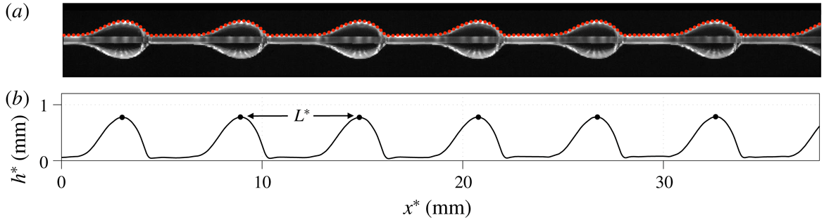
as defined later in § 3. Figure 2 shows a representative experimental frame and the film profile produced after the data are processed.
Experimental frame (a) and processed data analysis (b) for fibre radius
 $R^{\ast }=0.1~\text{mm}$
, nozzle inner diameter
 $ID=0.8~\text{mm}$
, and flow rate
 $Q_{m}^{\ast }=0.04~\text{g}~\text{s}^{-1}$
, shown at a distance 8–10 mm from the nozzle. The red dots superimposed on the experimental frame correspond to the extracted film profile and the black dots on the bottom plot correspond to the locations of the maxima. The average distance between two maxima is
 $L^{\ast }=5.92~\text{mm}$
and the film thickness between the drops ranges from 0.095 to 0.120 mm.

The uncertainties in the parameters obtained from our image processing are estimated in terms of a single pixel scaling and the selection of the colour value for the contour. The estimated uncertainty is
 $\pm 0.08~\text{mm}$
for the streamwise length and
 $\pm 0.10~\text{mm}$
for the bead height. Using a total of 1000 images for each run, we measure the averages for maximum fluid height, mass, bead speed and distance between two subsequent beads.
3 Model formulation
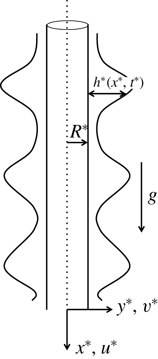
We consider a flow of two-dimensional axisymmetric Newtonian fluid down a vertical cylinder of radius
 $R^{\ast }$
(see figure 3). The liquid properties, including the surface tension
 $\unicode[STIX]{x1D70E}$
, density
 $\unicode[STIX]{x1D70C}$
and kinematic viscosity
 $\unicode[STIX]{x1D708}$
, are all assumed to be constant. This model formulation does not include the nozzle size as a system parameter because we are interested in the flow downstream where the nozzle does not affect the dynamics. Instead, we consider the scales for frequency and mass of the droplets, which depend on the nozzle size (Sadeghpour et al.
Reference Sadeghpour, Zeng and Ju2017). We will discuss this dependence later in appendix B. We review below the derivation of the governing equations and boundary conditions by Ruyer-Quil et al. (Reference Ruyer-Quil, Treveleyan, Giorgiutti-Dauphiné, Duprat and Kalliadasis2008) and Craster & Matar (Reference Craster and Matar2006) and discuss our inclusion of additional physics related to slip, curvature and wetting properties.
Schematic of a thin liquid film flowing down a vertical cylindrical fibre.

The dimensional Navier–Stokes equations for axisymmetric flows are
 $$\begin{eqnarray}\displaystyle & \displaystyle u_{t^{\ast }}^{\ast }+u^{\ast }u_{x^{\ast }}^{\ast }+v^{\ast }u_{y^{\ast }}^{\ast }=-\frac{1}{\unicode[STIX]{x1D70C}}(p_{x^{\ast }}^{\ast }+\unicode[STIX]{x1D6F1}_{x^{\ast }}^{\ast })+g+\unicode[STIX]{x1D708}\left(u_{x^{\ast }x^{\ast }}^{\ast }+\frac{u_{y^{\ast }}^{\ast }}{y^{\ast }}+u_{y^{\ast }y^{\ast }}^{\ast }\right), & \displaystyle\end{eqnarray}$$
 $$\begin{eqnarray}\displaystyle & \displaystyle v_{t^{\ast }}^{\ast }+v^{\ast }v_{y^{\ast }}^{\ast }+u^{\ast }v_{x^{\ast }}^{\ast }=-\frac{p_{y^{\ast }}^{\ast }}{\unicode[STIX]{x1D70C}}+\unicode[STIX]{x1D708}\left(\frac{v_{y^{\ast }}^{\ast }}{y^{\ast }}+v_{y^{\ast }y^{\ast }}^{\ast }-\frac{v^{\ast }}{y^{\ast 2}}+v_{x^{\ast }x^{\ast }}^{\ast }\right), & \displaystyle\end{eqnarray}$$
where
 $t^{\ast }$
represents the time,
 $u^{\ast }$
and
 $v^{\ast }$
represent the axial and radial components of the velocity,
 $p^{\ast }$
is the pressure and
 $g$
is the gravitational acceleration. We adopt the functional form of the disjoining pressure used in Reisfeld & Bankoff (Reference Reisfeld and Bankoff1992) and introduce the film stabilization term
 $\unicode[STIX]{x1D6F1}^{\ast }(h^{\ast })$
,
 $$\begin{eqnarray}\unicode[STIX]{x1D6F1}^{\ast }(h^{\ast })=-\frac{A^{\ast }}{{h^{\ast }}^{3}},\end{eqnarray}$$
where
 $A^{\ast }$
is a stabilization parameter. The equation of continuity is given by
 $$\begin{eqnarray}v_{y^{\ast }}^{\ast }+\frac{v^{\ast }}{y^{\ast }}+u_{x^{\ast }}^{\ast }=0.\end{eqnarray}$$
Along the fibre, at the interface between the solid substrate and the fluid
 $y^{\ast }=R^{\ast }$
, we impose the Navier slip and no-penetration boundary conditions:
 $$\begin{eqnarray}v^{\ast }=0,\quad u^{\ast }=\unicode[STIX]{x1D706}^{\ast }u_{y^{\ast }}^{\ast }\quad \text{at }y^{\ast }=R^{\ast },\end{eqnarray}$$
where
 $\unicode[STIX]{x1D706}^{\ast }>0$
is the slip length in standard slip models (Münch, Wagner & Witelski Reference Münch, Wagner and Witelski2005; Haefner et al.
Reference Haefner, Benzaquen, Bäumchen, Salez, Peters, McGraw, Jacobs, Raphaël and Dalnoki-Veress2015). The no-slip boundary condition corresponds to
 $\unicode[STIX]{x1D706}^{\ast }=0$
. Typical slip lengths for polymeric liquids such as silicone oil range from
 $1$
to
 $10~\unicode[STIX]{x03BC}\text{m}$
(Quéré Reference Quéré1990; Halpern & Wei Reference Halpern and Wei2017). The normal and shear stress balances on the free surface
 $y^{\ast }=R^{\ast }+h^{\ast }$
are given by
 $$\begin{eqnarray}\displaystyle & \displaystyle p^{\ast }=\frac{2\unicode[STIX]{x1D707}}{1+h_{x^{\ast }}^{\ast 2}}(h_{x^{\ast }}^{\ast 2}u_{x^{\ast }}^{\ast }-h_{x^{\ast }}^{\ast }(v_{x^{\ast }}^{\ast }+u_{y^{\ast }}^{\ast })+v_{y^{\ast }}^{\ast })+\frac{\unicode[STIX]{x1D70E}}{(1+h_{x^{\ast }}^{\ast 2})^{3/2}}\left(\frac{1+h_{x^{\ast }}^{\ast 2}}{R^{\ast }+h^{\ast }}-h_{x^{\ast }x^{\ast }}^{\ast }\right),\quad & \displaystyle\end{eqnarray}$$
 $$\begin{eqnarray}\displaystyle & \displaystyle (1-h_{x^{\ast }}^{\ast 2})(v_{x^{\ast }}^{\ast }+u_{y^{\ast }}^{\ast })+2h_{x^{\ast }}^{\ast }(v_{y^{\ast }}^{\ast }-u_{x^{\ast }}^{\ast })=0, & \displaystyle\end{eqnarray}$$
where
 $\unicode[STIX]{x1D707}$
is the dynamic viscosity, and
 $\unicode[STIX]{x1D70E}$
scales the total curvature which consists of a destabilizing azimuthal curvature term and a stabilizing axial curvature term. We then complete the system by including the kinematic boundary condition on the free surface
 $y^{\ast }=R^{\ast }+h^{\ast }$
,
 $$\begin{eqnarray}h_{t^{\ast }}^{\ast }+u^{\ast }h_{x^{\ast }}^{\ast }=v^{\ast }\quad \text{at }y^{\ast }=R^{\ast }+h^{\ast }.\end{eqnarray}$$
The next step is to choose the appropriate dimensionless parameters in order to non-dimensionalize the model. Following Duprat et al. (Reference Duprat, Ruyer-Quil and Giorgiutti-Dauphiné2009) we choose the scales for the system as follows: the length scale in the radial direction
 $y$
is
 ${\mathcal{H}}$
, and the length scale in the streamwise direction
 $x$
is
 ${\mathcal{L}}={\mathcal{H}}/\unicode[STIX]{x1D716}$
. The scale ratio
 $\unicode[STIX]{x1D716}$
is set by the balance between the surface tension term
 $\unicode[STIX]{x1D70E}h_{x^{\ast }x^{\ast }x^{\ast }}^{\ast }$
, arising from
 $p_{x^{\ast }}^{\ast }$
, and the gravity
 $g$
, and is given by
 $\unicode[STIX]{x1D716}=(\unicode[STIX]{x1D70C}g{\mathcal{H}}^{2}/\unicode[STIX]{x1D70E})^{1/3}$
. This scale ratio is small (around
 $0.4$
) in typical experiments and can also be rewritten as
 $\unicode[STIX]{x1D716}=We^{-1/3}$
, where the Weber number
 $We=(l_{c}/{\mathcal{H}})^{2}$
compares the capillary length
 $l_{c}=\sqrt{\unicode[STIX]{x1D70E}/(\unicode[STIX]{x1D70C}g)}$
to the radial length scale
 ${\mathcal{H}}$
. Then the characteristic streamwise velocity is
 ${\mathcal{U}}=(g{\mathcal{H}}^{2})/\unicode[STIX]{x1D708}$
, and the pressure and time scales are given by
 $\unicode[STIX]{x1D70C}g{\mathcal{L}}$
and
 $(\unicode[STIX]{x1D708}{\mathcal{L}})/(g{\mathcal{H}}^{2})$
, respectively. With these scales, we drop the star superscript in (3.1) and write the non-dimensional Navier–Stokes equations using dimensionless variables in the form
 $$\begin{eqnarray}\displaystyle & \displaystyle \unicode[STIX]{x1D716}^{2}Re(u_{t}+uu_{x}+vu_{y})=-p_{x}-\unicode[STIX]{x1D6F1}_{x}+1+\frac{u_{y}}{y}+u_{yy}+\unicode[STIX]{x1D716}^{2}u_{xx}, & \displaystyle\end{eqnarray}$$
 $$\begin{eqnarray}\displaystyle & \displaystyle \unicode[STIX]{x1D716}^{4}Re(v_{t}+vv_{y}+uv_{x})=-p_{y}+\unicode[STIX]{x1D716}^{2}\left(\frac{v_{y}}{y}+v_{yy}-\frac{v}{y^{2}}\right)+\unicode[STIX]{x1D716}^{4}v_{xx}, & \displaystyle\end{eqnarray}$$
where the Reynolds number
 $Re={\mathcal{U}}{\mathcal{L}}/\unicode[STIX]{x1D708}$
. The dimensionless continuity equation is identical to (3.1d
) in form. The balances of normal and tangential stresses at
 $y=h+R$
are expressed as
 $$\begin{eqnarray}(1-\unicode[STIX]{x1D716}^{2}h_{x}^{2})(\unicode[STIX]{x1D716}^{2}v_{x}+u_{y})+2\unicode[STIX]{x1D716}^{2}h_{x}(v_{y}-u_{x})=0,\end{eqnarray}$$
 $$\begin{eqnarray}\displaystyle p & = & \displaystyle \frac{\unicode[STIX]{x1D6FC}}{\unicode[STIX]{x1D716}^{2}(1+\unicode[STIX]{x1D6FC}h)(1+\unicode[STIX]{x1D716}^{2}h_{x}^{2})^{1/2}}-\frac{h_{xx}}{(1+\unicode[STIX]{x1D716}^{2}h_{x}^{2})^{3/2}}\nonumber\\ \displaystyle & & \displaystyle +\,\frac{\unicode[STIX]{x1D716}^{4}}{1+\unicode[STIX]{x1D716}^{2}h_{x}^{2}}[h_{x}^{2}u_{x}-h_{x}v_{x}+\unicode[STIX]{x1D716}^{2}(-h_{x}u_{y}+v_{y})],\end{eqnarray}$$
where the dimensionless parameter
 $\unicode[STIX]{x1D6FC}={\mathcal{H}}/R^{\ast }$
is the aspect ratio of the characteristic radial length scale and the fibre radius, and the dimensionless fibre radius
 $R=R^{\ast }/{\mathcal{H}}$
. The slip and no-penetration boundary conditions on
 $y=R$
are
 $$\begin{eqnarray}v=0,\quad u=\unicode[STIX]{x1D706}u_{y},\end{eqnarray}$$
where the non-dimensional slip length
 $\unicode[STIX]{x1D706}=\unicode[STIX]{x1D706}^{\ast }/{\mathcal{H}}$
. The kinematic boundary condition remains unaltered in its form.
We next simplify the above set of governing equations by following Ruyer-Quil et al. (Reference Ruyer-Quil, Treveleyan, Giorgiutti-Dauphiné, Duprat and Kalliadasis2008). Under the lubrication approximation, the inertial contributions can be neglected since
 $Re=O(1)$
and
 $\unicode[STIX]{x1D716}\ll 1$
. Note that we do not assume the small ratio
 $\unicode[STIX]{x1D6FC}$
between the liquid film thickness and the fibre radius. Omitting the terms of order
 $O(\unicode[STIX]{x1D716}^{2})$
, we rewrite the leading-order non-dimensional reduced momentum and continuity equations for the velocity field
 $(u,v)$
and the dynamic pressure
 $p$
as
 $$\begin{eqnarray}\displaystyle & \displaystyle 1-\frac{\unicode[STIX]{x2202}p}{\unicode[STIX]{x2202}x}-\frac{\unicode[STIX]{x2202}\unicode[STIX]{x1D6F1}}{\unicode[STIX]{x2202}x}+\frac{\unicode[STIX]{x2202}^{2}u}{\unicode[STIX]{x2202}y^{2}}+\frac{u_{y}}{y}=0, & \displaystyle\end{eqnarray}$$
 $$\begin{eqnarray}\displaystyle & \displaystyle -\frac{\unicode[STIX]{x2202}p}{\unicode[STIX]{x2202}y}=0, & \displaystyle\end{eqnarray}$$
 $$\begin{eqnarray}\displaystyle & \displaystyle \frac{\unicode[STIX]{x2202}u}{\unicode[STIX]{x2202}x}+\frac{\unicode[STIX]{x2202}v}{\unicode[STIX]{x2202}y}+\frac{v}{y}=0. & \displaystyle\end{eqnarray}$$
The balance of tangential stresses at the free surface
 $y=h+R$
is reduced to
 $$\begin{eqnarray}u_{y}=0.\end{eqnarray}$$
The destabilizing azimuthal curvature and the stabilizing streamwise curvature terms in (3.2d
) are both important throughout the liquid film. For
 $\unicode[STIX]{x1D716}\ll 1$
a formal expansion of the azimuthal curvature term in (3.2d
) yields
 $$\begin{eqnarray}\frac{\unicode[STIX]{x1D6FC}}{\unicode[STIX]{x1D716}^{2}(1+\unicode[STIX]{x1D6FC}h)\sqrt{1+\unicode[STIX]{x1D716}^{2}h_{x}^{2}}}=\frac{\unicode[STIX]{x1D6FC}}{\unicode[STIX]{x1D716}^{2}(1+\unicode[STIX]{x1D6FC}h)}\left(1-\frac{1}{2}\unicode[STIX]{x1D716}^{2}h_{x}^{2}+O(\unicode[STIX]{x1D716}^{4})\right),\end{eqnarray}$$
which shows that this term is of order
 $O(\unicode[STIX]{x1D6FC}/\unicode[STIX]{x1D716}^{2})$
, for both cases
 $\unicode[STIX]{x1D6FC}h\ll 1$
and
 $\unicode[STIX]{x1D6FC}h=O(1)$
. At the steep front of a moving droplet, we have
 $h_{x}=O(1)$
, and the second term in the expansion contributes an additional
 $O(\unicode[STIX]{x1D6FC})$
term to the dynamic pressure. Similarly, for the streamwise curvature term in (3.2d
), we have
 $$\begin{eqnarray}\frac{h_{xx}}{(1+\unicode[STIX]{x1D716}^{2}h_{x}^{2})^{3/2}}=h_{xx}\left(1-\frac{3}{2}\unicode[STIX]{x1D716}^{2}h_{x}^{2}+O(\unicode[STIX]{x1D716}^{4})\right).\end{eqnarray}$$
At the front of the moving droplet, the
 $O(\unicode[STIX]{x1D716}^{2})$
term introduced by the nonlinear curvature is negligible. Therefore, we only keep a fully nonlinear azimuthal curvature term and use the linearized curvature in the streamwise direction. The balance of normal stresses at the free surface
 $y=h+R$
is then reduced to
 $$\begin{eqnarray}p=\frac{\unicode[STIX]{x1D6FC}}{\unicode[STIX]{x1D716}^{2}(1+\unicode[STIX]{x1D6FC}h)\sqrt{1+\unicode[STIX]{x1D716}^{2}h_{x}^{2}}}-\frac{\unicode[STIX]{x2202}^{2}h}{\unicode[STIX]{x2202}x^{2}}.\end{eqnarray}$$
It is important to note that the first term on the right-hand side of (3.3g
) accounts for the balance between the azimuthal and axial scales characterized by
 $\unicode[STIX]{x1D6FC}$
and
 $\unicode[STIX]{x1D716}$
. We will further discuss appropriate forms of this term for different cases later.
To derive the evolution equation for
 $h$
from above, we first consider a uniform Nusselt flow without any interfacial instabilities. The velocity field of this flow is obtained by balancing the viscosity and gravity acceleration in (3.2). That is, the streamwise velocity
 $u_{0}$
of the Nusselt flow satisfies the reduced system
 $$\begin{eqnarray}1+\frac{\unicode[STIX]{x2202}^{2}u_{0}}{\unicode[STIX]{x2202}y^{2}}+\frac{1}{y}\frac{\unicode[STIX]{x2202}u_{0}}{\unicode[STIX]{x2202}y}=0,\end{eqnarray}$$
with boundary conditions
 $$\begin{eqnarray}\frac{\unicode[STIX]{x2202}u_{0}}{\unicode[STIX]{x2202}y}=0\quad \text{at }y=h+R,\quad u_{0}=\unicode[STIX]{x1D706}\frac{\unicode[STIX]{x2202}u_{0}}{\unicode[STIX]{x2202}y}\quad \text{at }y=R.\end{eqnarray}$$
Solving (3.4) for
 $u_{0}$
leads to
 $$\begin{eqnarray}u_{0}(y)=-\frac{1}{4}(y^{2}-R^{2})+\frac{1}{2}(h+R)^{2}\ln \left(\frac{y}{R}\right)+h\unicode[STIX]{x1D706}\left(\frac{h}{2R}+1\right).\end{eqnarray}$$
The rescaled kinematic boundary conditions together with the slip and no-penetration boundary conditions (3.2e ) and the shear stress condition (3.3d ) lead to the mass conservation equation
 $$\begin{eqnarray}(1+\unicode[STIX]{x1D6FC}h)\frac{\unicode[STIX]{x2202}h}{\unicode[STIX]{x2202}t}+\frac{\unicode[STIX]{x2202}q}{\unicode[STIX]{x2202}x}=0,\quad \text{where }q=\frac{1}{R}\int _{R}^{h+R}uy\,\text{d}y.\end{eqnarray}$$
Following Ruyer-Quil et al. (Reference Ruyer-Quil, Treveleyan, Giorgiutti-Dauphiné, Duprat and Kalliadasis2008) where an approach based on a projection of the velocity field of a test function is used, we take the inner product of (3.3a
) with the Nusselt uniform solution
 $u_{0}$
, and obtain
 $$\begin{eqnarray}\int _{R}^{h+R}\left(1+u_{yy}+\frac{u_{y}}{y}\right)u_{0}y\,\text{d}y=\int _{R}^{h+R}(p_{x}+\unicode[STIX]{x1D6F1}_{x})u_{0}y\,\text{d}y.\end{eqnarray}$$
From equation (3.3b
), we see that the pressure
 $p$
is a function of
 $x$
only, and the right-hand side of the above equation becomes
 $p_{x}\bar{R}q_{0}$
. Note that the Nusselt solution
 $u_{0}$
satisfies (3.4). By integrating by parts and applying the slip and no-penetration boundary conditions (3.2e
) and the shear stress condition (3.3d
), we obtain
 $$\begin{eqnarray}q=\left(1-\frac{\unicode[STIX]{x2202}p}{\unicode[STIX]{x2202}x}-\frac{\unicode[STIX]{x2202}\unicode[STIX]{x1D6F1}}{\unicode[STIX]{x2202}x}\right)q_{0}.\end{eqnarray}$$
Here
 $q_{0}$
, the flow rate per unit circumference length for the uniform Nusselt layer, is
 $$\begin{eqnarray}q_{0}=\frac{1}{R}\int _{R}^{R+h}u_{0}y\,\text{d}y=\frac{h^{3}}{3}\unicode[STIX]{x1D719}(\unicode[STIX]{x1D6FC}h)+\frac{h^{2}}{4}(\unicode[STIX]{x1D6FC}h+2)^{2}\unicode[STIX]{x1D706},\end{eqnarray}$$
where the shape factor
 $\unicode[STIX]{x1D719}$
is a function defined by
 $$\begin{eqnarray}\unicode[STIX]{x1D719}(X)=\frac{3}{16X^{3}}[(1+X)^{4}(4\log (1+X)-3)+4(1+X)^{2}-1].\end{eqnarray}$$
Given a dimensional volumetric flow rate
 $Q_{m}^{\ast }$
and fibre radius
 $R^{\ast }$
, we define the volumetric flow rate per circumference unit
 $q_{0}^{\ast }$
as
 $q_{0}^{\ast }=Q_{m}^{\ast }/(2\unicode[STIX]{x03C0}\unicode[STIX]{x1D70C}R^{\ast })$
. From (3.9) the characteristic axial length scale
 ${\mathcal{H}}$
for a uniform Nusselt flow can then be obtained. For the no-slip case
 $\unicode[STIX]{x1D706}=0$
, equation (3.9) gives the Nusselt solution
 $h\equiv {\mathcal{H}}$
used in Ruyer-Quil et al. (Reference Ruyer-Quil, Treveleyan, Giorgiutti-Dauphiné, Duprat and Kalliadasis2008) and Duprat et al. (Reference Duprat, Ruyer-Quil and Giorgiutti-Dauphiné2009).
Finally, by rescaling the time scale
 $t\rightarrow t/\unicode[STIX]{x1D719}(\unicode[STIX]{x1D6FC})$
and combining (3.6), (3.9) and (3.8), we obtain the dimensionless governing equation
 $$\begin{eqnarray}\frac{\unicode[STIX]{x2202}}{\unicode[STIX]{x2202}t}\left(h+\frac{\unicode[STIX]{x1D6FC}}{2}h^{2}\right)+\frac{\unicode[STIX]{x2202}}{\unicode[STIX]{x2202}x}\left[{\mathcal{M}}(h)\left(1-\frac{\unicode[STIX]{x2202}p}{\unicode[STIX]{x2202}x}-\frac{\unicode[STIX]{x2202}\unicode[STIX]{x1D6F1}}{\unicode[STIX]{x2202}x}\right)\right]=0,\end{eqnarray}$$
where the mobility function takes the form
 $$\begin{eqnarray}{\mathcal{M}}(h;\unicode[STIX]{x1D706},\unicode[STIX]{x1D6FC})=\frac{h^{3}}{3}\frac{\unicode[STIX]{x1D719}(\unicode[STIX]{x1D6FC}h)}{\unicode[STIX]{x1D719}(\unicode[STIX]{x1D6FC})}+\frac{h^{2}(\unicode[STIX]{x1D6FC}h+2)^{2}\unicode[STIX]{x1D706}}{4\unicode[STIX]{x1D719}(\unicode[STIX]{x1D6FC})}.\end{eqnarray}$$
This choice of time scale leads to a normalized mobility function such that
 ${\mathcal{M}}=1/3$
for
 $h=1$
and
 $\unicode[STIX]{x1D706}=0$
. Moreover, in the limit of the aspect ratio
 $\unicode[STIX]{x1D6FC}\rightarrow 0$
, the mobility function becomes
 $$\begin{eqnarray}{\mathcal{M}}(h;\unicode[STIX]{x1D706},\unicode[STIX]{x1D6FC})=\frac{1}{3}h^{2}(h+3\unicode[STIX]{x1D706})+\frac{\unicode[STIX]{x1D6FC}}{3}h^{2}(h+3\unicode[STIX]{x1D706})(h-1)+O(\unicode[STIX]{x1D6FC}^{2}),\end{eqnarray}$$
and its leading-order term agrees with the mobility function used in the slip model proposed by Halpern & Wei (Reference Halpern and Wei2017). Substituting (3.3g
) into (3.11) yields an evolution equation for the film thickness
 $h(x,t)$
:

where
 ${\mathcal{Z}}(h)$
includes the destabilizing azimuthal curvature of the film and the film stabilization term. Comparing (3.14) and (3.11), and using (3.3g
) with a scaling parameter
 $\unicode[STIX]{x1D702}=\unicode[STIX]{x1D716}^{2}$
, we write the complete form of
 ${\mathcal{Z}}(h)$
as
 $$\begin{eqnarray}{\mathcal{Z}}(h)=p+h_{xx}+\unicode[STIX]{x1D6F1}=\frac{\unicode[STIX]{x1D6FC}}{\unicode[STIX]{x1D702}(1+\unicode[STIX]{x1D6FC}h)\sqrt{1+\unicode[STIX]{x1D702}h_{x}^{2}}}+\unicode[STIX]{x1D6F1}(h).\end{eqnarray}$$
Equation (3.14) is a fourth-order nonlinear partial differential equation (PDE) for the thickness
 $h(x,t)$
. This model accounts for the surface tension, gravity and azimuthal instabilities, but neglects inertia and streamwise viscous dissipation (Ruyer-Quil et al.
Reference Ruyer-Quil, Trevelyan, Giorgiutti-Dauphiné, Duprat and Kalliadasis2009). When the Rayleigh–Plateau instability dominates over the inertia and streamwise viscous dissipation, our model (3.14) is expected to provide a good agreement with experimental data.
Different forms of
 ${\mathcal{Z}}(h)$
appear in the literature to represent the azimuthal curvature of the film. For instance, Yu & Hinch (Reference Yu and Hinch2013) assumed that the film is much thinner than the fibre radius,
 ${\mathcal{H}}\ll R^{\ast }$
(which corresponds to
 $\unicode[STIX]{x1D6FC}\ll 1$
), and used a simple form
 ${\mathcal{Z}}(h)=-(\unicode[STIX]{x1D6FC}/\unicode[STIX]{x1D716})^{2}h$
where the leading-order constant term in the expansion of the azimuthal curvature is neglected. For thicker films that are of interest to the present study,
 $\unicode[STIX]{x1D6FC}=O(1)$
and
 $\unicode[STIX]{x1D6FC}h$
is at most
 $O(1)$
so we use (3.16) as the first form of
 ${\mathcal{Z}}$
,
 $$\begin{eqnarray}{\mathcal{Z}}_{CM}(h)=\frac{\unicode[STIX]{x1D6FC}}{\unicode[STIX]{x1D702}(1+\unicode[STIX]{x1D6FC}h)},\end{eqnarray}$$
following Craster & Matar (Reference Craster and Matar2006), Sisoev et al. (Reference Sisoev, Craster, Matar and Gerasimov2006) and Ruyer-Quil et al. (Reference Ruyer-Quil, Treveleyan, Giorgiutti-Dauphiné, Duprat and Kalliadasis2008, Reference Ruyer-Quil, Trevelyan, Giorgiutti-Dauphiné, Duprat and Kalliadasis2009). With
 ${\mathcal{Z}}_{{\mathcal{C}}{\mathcal{M}}}(h)$
in (3.16) and
 $\unicode[STIX]{x1D706}=0$
, the evolution equation (3.14) reduces to
 $$\begin{eqnarray}(\text{CM})\qquad \frac{\unicode[STIX]{x2202}}{\unicode[STIX]{x2202}t}\left(h+\frac{\unicode[STIX]{x1D6FC}}{2}h^{2}\right)+\frac{\unicode[STIX]{x2202}}{\unicode[STIX]{x2202}x}\left[\frac{h^{3}}{3}\frac{\unicode[STIX]{x1D719}(\unicode[STIX]{x1D6FC}h)}{\unicode[STIX]{x1D719}(\unicode[STIX]{x1D6FC})}\left(1-\frac{\unicode[STIX]{x2202}}{\unicode[STIX]{x2202}x}\left[\frac{\unicode[STIX]{x1D6FC}}{\unicode[STIX]{x1D702}(1+\unicode[STIX]{x1D6FC}h)}-h_{xx}\right]\right)\right]=0,\end{eqnarray}$$
which is consistent with the evolution equation derived by Craster & Matar (Reference Craster and Matar2006) except for a scaling difference. For the rest of this paper, we will refer to the model (3.17) as the Craster & Matar (CM) model.
To incorporate the slip effects under the framework of the CM model, we use the evolution equation (3.14) with the non-dimensional slip length
 $\unicode[STIX]{x1D706}>0$
, the mobility function (3.12) and the azimuthal curvature term (3.16). This will be referred to as the Slip Craster & Matar (SCM) model. We will show that this slip model promotes droplet formation and leads to an increased speed of propagation.
With the aspect ratio
 $\unicode[STIX]{x1D6FC}$
being of
 $O(1)$
, in the limit as
 $\unicode[STIX]{x1D702}\rightarrow 0$
, (3.16) becomes singular. To address this problem, in this paper we will consider two additional forms of
 ${\mathcal{Z}}(h)$
to reflect the balance between the azimuthal and axial scales under different flow conditions.
As the second form of
 ${\mathcal{Z}}$
, we define
 $$\begin{eqnarray}{\mathcal{Z}}_{FC}(h)=\frac{\unicode[STIX]{x1D6FC}}{\unicode[STIX]{x1D702}(1+\unicode[STIX]{x1D6FC}h)\sqrt{1+\unicode[STIX]{x1D702}h_{x}^{2}}}.\end{eqnarray}$$
This fully nonlinear azimuthal curvature term provides an
 $O(\unicode[STIX]{x1D6FC}/\unicode[STIX]{x1D702}^{3/2})$
contribution to the dynamic pressure near the advancing edge of the moving beads. It has been shown in many applications (Snoeijer Reference Snoeijer2006; Lopes, von Borries & Hazel Reference Lopes, von Borries and Hazel2018) that using the full expression for the curvature term can provide better accuracy for lubrication models, and this issue was recently reviewed in Thiele (Reference Thiele2018). We will show that the inclusion of the fully nonlinear curvature yields an increased speed of propagation of the travelling beads and partially improves agreement with our experimental results. Compared with the thick-film model proposed in Kliakhandler et al. (Reference Kliakhandler, Davis and Bankoff2001), where both curvature terms are fully nonlinear, our model has only a nonlinear azimuthal curvature term. The stabilizing axial curvature term is linearly approximated. For the remainder of this paper, we will refer to the evolution equation (3.14) with the mobility function (3.12) and the azimuthal curvature term (3.18) as the Full curvature model (FCM).
As the third form of
 ${\mathcal{Z}}$
, we include the film stabilization term to deal with the unbalanced azimuthal curvature term. Thus we replace (3.16) with
 $$\begin{eqnarray}{\mathcal{Z}}_{FS}(h)=\frac{\unicode[STIX]{x1D6FC}}{\unicode[STIX]{x1D702}(1+\unicode[STIX]{x1D6FC}h)}-\frac{A}{h^{3}}.\end{eqnarray}$$
The last term of (3.19) is motivated by the functional form of the long-range attractive part of the well-known apolar van der Waals model (de Gennes Reference de Gennes1985; Oron, Davis & Bankoff Reference Oron, Davis and Bankoff1997; Oron & Bankoff Reference Oron and Bankoff2001) for the well-wetting liquids used in our experiments. The stabilization parameter
 $A=(\unicode[STIX]{x1D6FC}^{2}\unicode[STIX]{x1D716}_{p}^{4})/(3\unicode[STIX]{x1D702}(\unicode[STIX]{x1D6FC}\unicode[STIX]{x1D716}_{p}+1)^{2})>0$
is expressed in terms of a dimensionless thickness
 $\unicode[STIX]{x1D716}_{p}$
, below which a thin uniform fluid layer on a fibre is stable. We will discuss this stability criterion further in § 4. The film stabilization term is found to significantly improve agreement with our experimental data as discussed in § 5. The model (3.14) with
 ${\mathcal{M}}(h)$
from (3.12) and the azimuthal curvature with film stabilization term (3.19) will be referred to as the film stabilization model (FSM).
A summary of the models using (3.14).

In summary, this paper considers four versions of the model (3.14) listed in table 1 to incorporate different physical effects. When contrasted with the CM model, which corresponds to the asymptotic model studied in Craster & Matar (Reference Craster and Matar2006), the other three new models take into consideration the slip effects, the nonlinear curvature and the film stabilization term, respectively.
4 Film stabilization model and stability analysis
In this section, we derive the stabilization parameter
 $A$
in (3.19) and study its effects. Using a stability analysis study, we show that
 $A>0$
is important to reproduce the stable travelling wave solutions (TWS) observed in experiments.
We begin by examining the linear stability of the uniform Nusselt solution. Following the approach in Craster & Matar (Reference Craster and Matar2006), we perturb the uniform film (
 $h_{0}=1$
) by an infinitesimal Fourier mode,
 $$\begin{eqnarray}h=h_{0}+\unicode[STIX]{x1D6FF}\text{e}^{\text{i}kx+\unicode[STIX]{x1D6EC}t},\end{eqnarray}$$
where
 $k$
is the wavenumber,
 $\unicode[STIX]{x1D6EC}$
describes the growth rate of the perturbation and
 $\unicode[STIX]{x1D6FF}$
 $(\ll 1)$
is the initial amplitude. Expanding PDE (3.14) then gives the dispersion relation:
 $$\begin{eqnarray}\unicode[STIX]{x1D6EC}=-\text{i}kc_{k}(\unicode[STIX]{x1D6FC},\unicode[STIX]{x1D706})+\frac{k^{2}}{3(1+\unicode[STIX]{x1D6FC})}\left(\frac{\unicode[STIX]{x1D6FC}^{2}}{(1+\unicode[STIX]{x1D6FC})^{2}\unicode[STIX]{x1D702}}-k^{2}-3A\right)\left(1+\frac{3(\unicode[STIX]{x1D6FC}+2)^{2}\unicode[STIX]{x1D706}}{4\unicode[STIX]{x1D719}(\unicode[STIX]{x1D6FC})}\right),\end{eqnarray}$$
where
 $c_{k}$
is the speed of linear kinematic wave solutions of (3.14) for small wavenumbers,
 $$\begin{eqnarray}c_{k}(\unicode[STIX]{x1D6FC},\unicode[STIX]{x1D706})=\frac{1}{\unicode[STIX]{x1D6FC}+1}\left(1+\frac{\unicode[STIX]{x1D6FC}\unicode[STIX]{x1D719}^{\prime }(\unicode[STIX]{x1D6FC})}{3\unicode[STIX]{x1D719}(\unicode[STIX]{x1D6FC})}\right)+\frac{(\unicode[STIX]{x1D6FC}+2)\unicode[STIX]{x1D706}}{\unicode[STIX]{x1D719}(\unicode[STIX]{x1D6FC})},\end{eqnarray}$$
and it increases linearly with the presence of slip. The real part of
 $\unicode[STIX]{x1D6EC}$
is the effective growth rate, and the thickness
 $h_{0}=1$
is long-wave unstable with respect to perturbations with
 $0<k<k_{c}$
, where the critical wavenumber
 $k_{c}=[\unicode[STIX]{x1D6FC}^{2}/((1+\unicode[STIX]{x1D6FC})^{2}\unicode[STIX]{x1D702})-3A]^{1/2}$
. For
 $A=0$
this cut-off wavenumber corresponds to the classical Rayleigh–Plateau (RP) mode for the capillary instability of a viscous jet, where
 $Re(\unicode[STIX]{x1D6EC})=0$
at
 $k=k_{c}$
. The most unstable mode occurs at
 $k_{m}=[\unicode[STIX]{x1D6FC}^{2}/(2(1+\unicode[STIX]{x1D6FC})^{2}\unicode[STIX]{x1D702})-(3A/2)]^{1/2}$
, where the largest growth rate
 $\unicode[STIX]{x1D6EC}_{m}$
is attained. Equation (4.2) also shows that the slip effects always enhance the RP instability, which agrees with the work by Halpern & Wei (Reference Halpern and Wei2017).
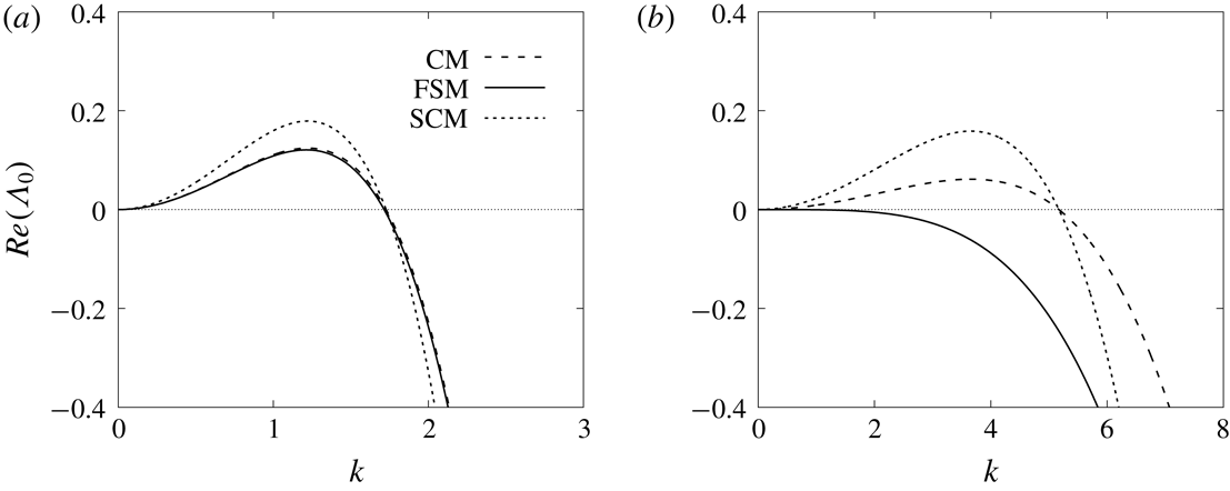
Dispersion relation plots of
 $Re(\unicode[STIX]{x1D6EC}_{0})$
against the wavenumber
 $k$
with the constant film thickness (a)
 $h_{0}=1$
and (b)
 $h_{0}=0.2$
for the CM model, the SCM with slip
 $\unicode[STIX]{x1D706}=0.1$
, and the FSM with
 $\unicode[STIX]{x1D716}_{p}=0.2$
, which corresponds to
 $A=0.027$
from (4.5). Other system parameters are
 $\unicode[STIX]{x1D6FC}=4.96$
and
 $\unicode[STIX]{x1D702}=0.23$
.

We repeat the above analysis for a uniform thin layer
 $h=h_{0}~({<}1)$
. The effective growth rate of disturbances with wavenumber
 $k$
is given by
 $$\begin{eqnarray}Re(\unicode[STIX]{x1D6EC}_{0})=\frac{k^{2}}{3h_{0}(\unicode[STIX]{x1D6FC}h_{0}+1)}\left(\frac{h_{0}^{4}\unicode[STIX]{x1D6FC}^{2}}{(\unicode[STIX]{x1D6FC}h_{0}+1)^{2}\unicode[STIX]{x1D702}}-k^{2}h_{0}^{4}-3A\right)\left(\frac{\unicode[STIX]{x1D719}(\unicode[STIX]{x1D6FC}h_{0})}{\unicode[STIX]{x1D719}(\unicode[STIX]{x1D6FC})}+\frac{3(\unicode[STIX]{x1D6FC}h_{0}+2)^{2}}{4h_{0}\unicode[STIX]{x1D719}(\unicode[STIX]{x1D6FC})}\unicode[STIX]{x1D706}\right).\end{eqnarray}$$
Figure 4 gives the dispersion relation (4.4) for the uniform Nusselt solution
 $h_{0}=1$
and a thinner undisturbed layer of
 $h_{0}=0.2$
under the CM, SCM and FSM models. The Nusselt solution
 $h_{0}=1$
is unstable for small wavenumbers for all three models. The finite slippage increases the growth rates of the unstable modes. For the CM and SCM models, the thinner undisturbed liquid layer (
 $h_{0}=0.2$
) is unstable over larger ranges of the wavenumber. In stark contrast, the FSM model saturates the unstable modes, rendering the thinner undisturbed layer linearly stable for all wavenumbers (see the solid curve in figure 4
b) for certain values of
 $A$
.
In the literature,
 $A$
is typically expressed as a Hamaker constant in terms of microscopic quantities (de Gennes Reference de Gennes1985). We instead choose the values of
 $A$
based on stable undisturbed liquid layers. Empirical observations of the thin-film layers between droplets indicate that these undisturbed liquid layers are comparable to the corresponding fibre radius
 $R^{\ast }$
. Therefore, we pick a coating thickness
 $\unicode[STIX]{x1D716}_{p}^{\ast }\approx R^{\ast }$
, obtained from experimental measurements. Using the dimensionless undisturbed layer thickness
 $\unicode[STIX]{x1D716}_{p}=\unicode[STIX]{x1D716}_{p}^{\ast }/{\mathcal{H}}$
and the dispersion relation in (4.4), we derive a formula for
 $\tilde{A}$
,
 $$\begin{eqnarray}\tilde{A}=\frac{\unicode[STIX]{x1D6FC}^{2}\unicode[STIX]{x1D716}_{p}^{4}}{3\unicode[STIX]{x1D702}(\unicode[STIX]{x1D6FC}\unicode[STIX]{x1D716}_{p}+1)^{2}}.\end{eqnarray}$$
For
 $A=\tilde{A}$
, any thin flat film of thickness less than the threshold value
 $\unicode[STIX]{x1D716}_{p}$
is linearly stable, i.e.
 $Re(\unicode[STIX]{x1D6EC}_{0})<0$
, for all wavenumbers.
We next examine the influences of the film stabilization terms (3.19) on the profiles and speeds of propagation of the travelling wave patterns governed by (3.14). We consider the model over a periodic domain
 $0\leqslant x\leqslant L$
and introduce a change of variables to the reference frame of the travelling wave,
 $$\begin{eqnarray}\unicode[STIX]{x1D709}=x-ct,\quad s=t,\quad h(x,t)=\tilde{h}(\unicode[STIX]{x1D709},s),\end{eqnarray}$$
where
 $c$
is the speed of the travelling wave. Then
 $\tilde{h}(\unicode[STIX]{x1D709},s)$
satisfies the PDE
 $$\begin{eqnarray}\frac{\unicode[STIX]{x2202}}{\unicode[STIX]{x2202}s}\left(\tilde{h}+\frac{\unicode[STIX]{x1D6FC}}{2}\tilde{h}^{2}\right)-c\frac{\unicode[STIX]{x2202}}{\unicode[STIX]{x2202}\unicode[STIX]{x1D709}}\left(\tilde{h}+\frac{\unicode[STIX]{x1D6FC}}{2}\tilde{h}^{2}\right)+\frac{\unicode[STIX]{x2202}}{\unicode[STIX]{x2202}\unicode[STIX]{x1D709}}\left[{\mathcal{M}}(\tilde{h})\left(1-\frac{\unicode[STIX]{x2202}}{\unicode[STIX]{x2202}\unicode[STIX]{x1D709}}[{\mathcal{Z}}(\tilde{h})-\tilde{h}_{\unicode[STIX]{x1D709}\unicode[STIX]{x1D709}}]\right)\right]=0.\end{eqnarray}$$
The travelling wave solution
 $H(\unicode[STIX]{x1D709})$
is a steady state of the PDE (4.7) and satisfies the fourth-order ordinary differential equation (ODE)
 $$\begin{eqnarray}c\frac{\text{d}}{\text{d}\unicode[STIX]{x1D709}}\left(H+\frac{\unicode[STIX]{x1D6FC}}{2}H^{2}\right)=\frac{\text{d}}{\text{d}\unicode[STIX]{x1D709}}\left[{\mathcal{M}}(H)\left(1-\frac{\text{d}}{\text{d}\unicode[STIX]{x1D709}}\left[{\mathcal{Z}}(H)-H_{\unicode[STIX]{x1D709}\unicode[STIX]{x1D709}}\right]\right)\right].\end{eqnarray}$$
This is a nonlinear eigenvalue problem, where the speed of propagation
 $c$
corresponds to the eigenvalue. The effects of slippage
 $\unicode[STIX]{x1D706}$
and full nonlinear curvature (3.18) will be studied in § 5.3. Newton’s method is used to solve the nonlinear ODE (4.8) where the speed
 $c$
is treated as an unknown variable. In order to achieve local uniqueness, we impose a constraint of mass conservation,
 $$\begin{eqnarray}\int _{0}^{L}H+\frac{\unicode[STIX]{x1D6FC}}{2}H^{2}\,\text{d}\unicode[STIX]{x1D709}=M_{0},\end{eqnarray}$$
for given values of mass
 $M_{0}$
and wavelength
 $L$
extracted from our experimentally obtained liquid film profiles. We also set
 $H(\unicode[STIX]{x1D709}_{0})=H_{0}$
for
 $0\leqslant \unicode[STIX]{x1D709}_{0}\leqslant L$
.
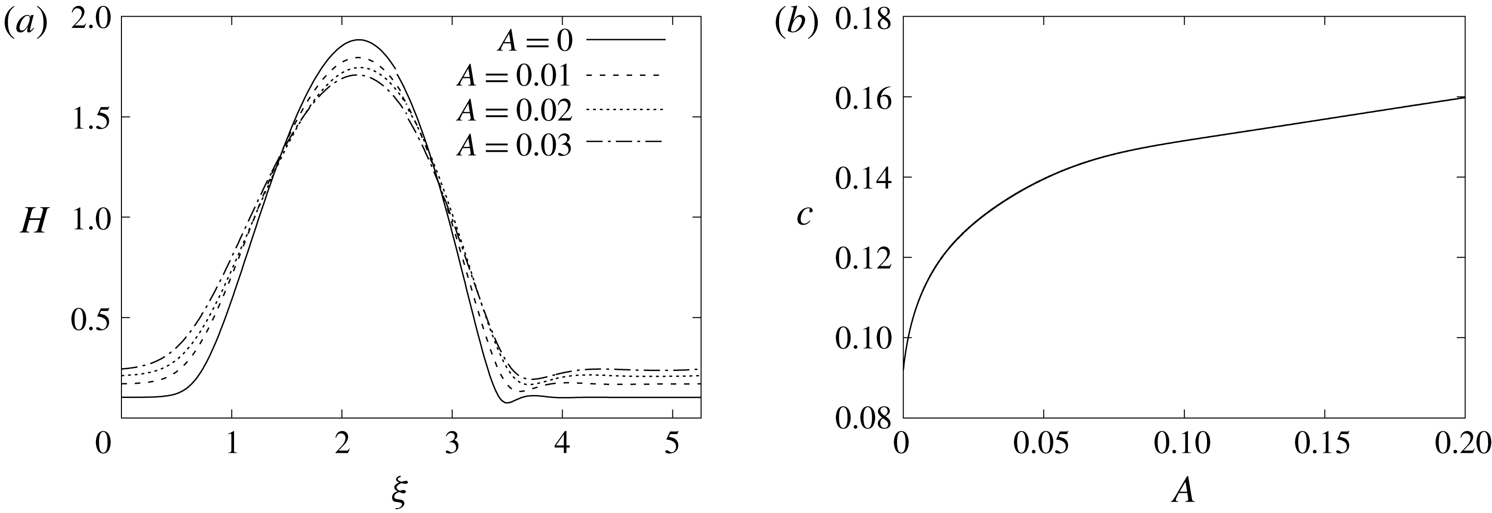
Numerical investigations reveal that including the film stabilization term in (3.19) enhances the moving speed of travelling wave solutions. In figure 5(a), we plot the profiles of travelling wave solutions with a varying stabilization parameter
 $A$
and identical mass constraint
 $M_{0}$
and period
 $L$
. Since a larger value of
 $A$
corresponds to a stronger wetting potential in the lubrication model, the near-flat coating thickness increases with increasing
 $A$
, as expected. Correspondingly, the height of the beads decreases as the coating thickness increases under the fixed overall mass constraint. That is, the presence of the film stabilization term saturates capillary instabilities and generates smaller moving beads. Figure 5(b) shows that the predicted velocity
 $c$
increases with the parameter
 $A$
superlinearly for small
 $A$
, and increases linearly as
 $A$
becomes larger. In § 5.1, we will show that, compared to the CM model (3.17), the FSM model with parameter
 $A$
given by (4.5) significantly improves predictions of the travelling wave velocity against experimental observations.
Travelling wave solutions of (4.8) with a varying stabilization parameter
 $A=0,0.01,0.02,0.03$
showing that (a) stronger regularization yields smaller droplet heights and thicker precursor layers and (b) the moving speed of drops is significantly increased with larger values of
 $A$
.

Earlier works have not reported a detailed stability analysis of the travelling wave. Therefore, we take a closer look at the linear stability of the travelling wave solutions in the film stabilization model. We consider a positive periodic travelling wave solution
 $H(\unicode[STIX]{x1D709})$
over the domain
 $0\leqslant \unicode[STIX]{x1D709}\leqslant L$
, and perturb it by setting
 $\tilde{h}(\unicode[STIX]{x1D709},s)=H(\unicode[STIX]{x1D709})+\unicode[STIX]{x1D6FF}\unicode[STIX]{x1D6F9}(\unicode[STIX]{x1D709})\text{e}^{\unicode[STIX]{x1D6EC}s}$
, where
 $\unicode[STIX]{x1D6FF}\ll 1$
and
 $\unicode[STIX]{x1D6F9}(\unicode[STIX]{x1D709})$
is also
 $L$
-periodic. Here we only focus on perturbations of the same period since the dynamics in both RP and isolated droplet regimes have fixed spatial periods. More complicated droplet dynamics (Kalliadasis & Chang Reference Kalliadasis and Chang1994) in the convective regime is not investigated here. We linearize equation (4.7) around the steady state
 $H(\unicode[STIX]{x1D709})$
and obtain the
 $O(\unicode[STIX]{x1D6FF})$
equation
 $$\begin{eqnarray}\unicode[STIX]{x1D6EC}\unicode[STIX]{x1D6F9}=\mathscr{L}\unicode[STIX]{x1D6F9},\end{eqnarray}$$
where the linear operator
 $\mathscr{L}$
is
 $$\begin{eqnarray}\displaystyle \mathscr{L}\unicode[STIX]{x1D6F9} & \equiv & \displaystyle c\left(\frac{\text{d}}{\text{d}\unicode[STIX]{x1D709}}+\frac{\unicode[STIX]{x1D6FC}H^{\prime }}{1+\unicode[STIX]{x1D6FC}H}\right)\unicode[STIX]{x1D6F9}+\frac{1}{1+\unicode[STIX]{x1D6FC}H}\frac{\text{d}}{\text{d}\unicode[STIX]{x1D709}}\left({\mathcal{M}}(H)\frac{\text{d}}{\text{d}\unicode[STIX]{x1D709}}[{\mathcal{Z}}^{\prime }(H)\unicode[STIX]{x1D6F9}-\unicode[STIX]{x1D6F9}^{\prime \prime }]\right)\nonumber\\ \displaystyle & & \displaystyle -\,\frac{1}{1+\unicode[STIX]{x1D6FC}H}\frac{\text{d}}{\text{d}\unicode[STIX]{x1D709}}\left({\mathcal{M}}^{\prime }(H)\left[1-\frac{\text{d}}{\text{d}\unicode[STIX]{x1D709}}({\mathcal{Z}}(H)-H^{\prime \prime })\right]\unicode[STIX]{x1D6F9}\right).\end{eqnarray}$$
Here
 $\unicode[STIX]{x1D6F9}(\unicode[STIX]{x1D709})$
is a normalized eigenmode associated with an eigenvalue
 $\unicode[STIX]{x1D6EC}$
and
 $\Vert \unicode[STIX]{x1D6F9}\Vert _{2}=1$
. If there are any eigenvalues
 $\unicode[STIX]{x1D6EC}$
with
 $Re(\unicode[STIX]{x1D6EC})>0$
to the problem (4.10), then the periodic travelling wave solution
 $H(\unicode[STIX]{x1D709})$
is unstable. For simplicity we only focus on the case where a one-period solution fits in the domain, and numerically calculate the spectrum and corresponding eigenfunctions for the eigenproblem.
(a) The dependence of dominant eigenvalues of
 $H(\unicode[STIX]{x1D709})$
on the stabilization parameter
 $A$
for the eigenproblem (4.10) where the unstable eigenvalues are plotted in dashed lines and the stable eigenvalues are in solid lines. (b) Corresponding travelling wave profile
 $H$
and unstable eigenmodes
 $\unicode[STIX]{x1D6F9}_{1}$
,
 $\unicode[STIX]{x1D6F9}_{2}$
,
 $\unicode[STIX]{x1D6F9}_{3}$
for the CM model (
 $A=0$
). The parameters
 $(L,M_{0})=(8.86,22.16)$
correspond to the experiment with flow rate
 $Q_{m}^{\ast }=0.04~\text{g}~\text{s}^{-1}$
, fibre radius
 $R^{\ast }=0.1~\text{mm}$
and nozzle diameter
 $1.06~\text{mm}$
.

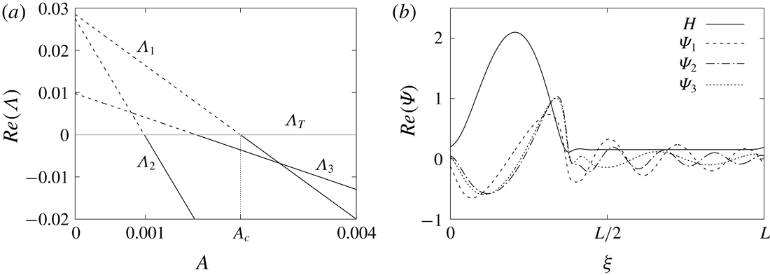
Figure 6(b) shows the unstable modes predicted by the CM model (
 $A$
= 0). These instabilities contradict the stable TWS from the corresponding experiment and generate small wavy patterns in the flat film connecting the moving beads. However, these instabilities can be saturated by the FSM model with an appropriate stabilization parameter
 $A$
. For a typical travelling wave solution
 $H(\unicode[STIX]{x1D709})$
to the FSM model, its dominant eigenvalues with a varying
 $A$
are plotted in figure 6(a). It shows that, without the film stabilization term (i.e.
 $A=0$
), the TWS is unstable. In addition to the translational eigenmode
 $\unicode[STIX]{x1D6EC}_{T}=0$
, the dominant unstable eigenvalues are given by complex conjugate pairs
 $\unicode[STIX]{x1D6EC}_{1}=0.0283\pm 0.756\text{i}$
,
 $\unicode[STIX]{x1D6EC}_{2}=0.0264\pm 1.006\text{i}$
, and
 $\unicode[STIX]{x1D6EC}_{3}=0.0097\pm 0.503\text{i}$
. Increasing the parameter
 $A$
yields three pairs of complex conjugate eigenvalues crossing the imaginary axis, suggesting three Hopf bifurcations occur at these crossing points. At each of these bifurcation points, a branch of time-periodic solution emerges corresponding to typical dynamics in the isolated droplet regime.
For
 $A>A_{c}$
all the eigenvalues of
 $H(\unicode[STIX]{x1D709})$
satisfy
 $Re(\unicode[STIX]{x1D6EC})<0$
and the travelling wave is stabilized. In § 5.2, we will show that the film stabilization term helps better arrest the stability transition from the RP regime to isolated droplet regime in experiments with different nozzle diameters.
5 Results
5.1 Experimental comparisons
Here, we present a comparison between physical experiments and two models, the film stabilization model (FSM) and the Craster & Matar (CM) model. Appendix A shows the range of nozzle sizes, fibre radii and flow rates for the experiments. For each experimental condition, we extract a characteristic period
 $L^{\ast }$
and bead liquid mass
 $M_{0}^{\ast }$
. We then use these as input parameters in our models. Appendix B describes how a unique travelling wave solution (TWS) is selected to compare with each experiment for both the FSM and CM models.
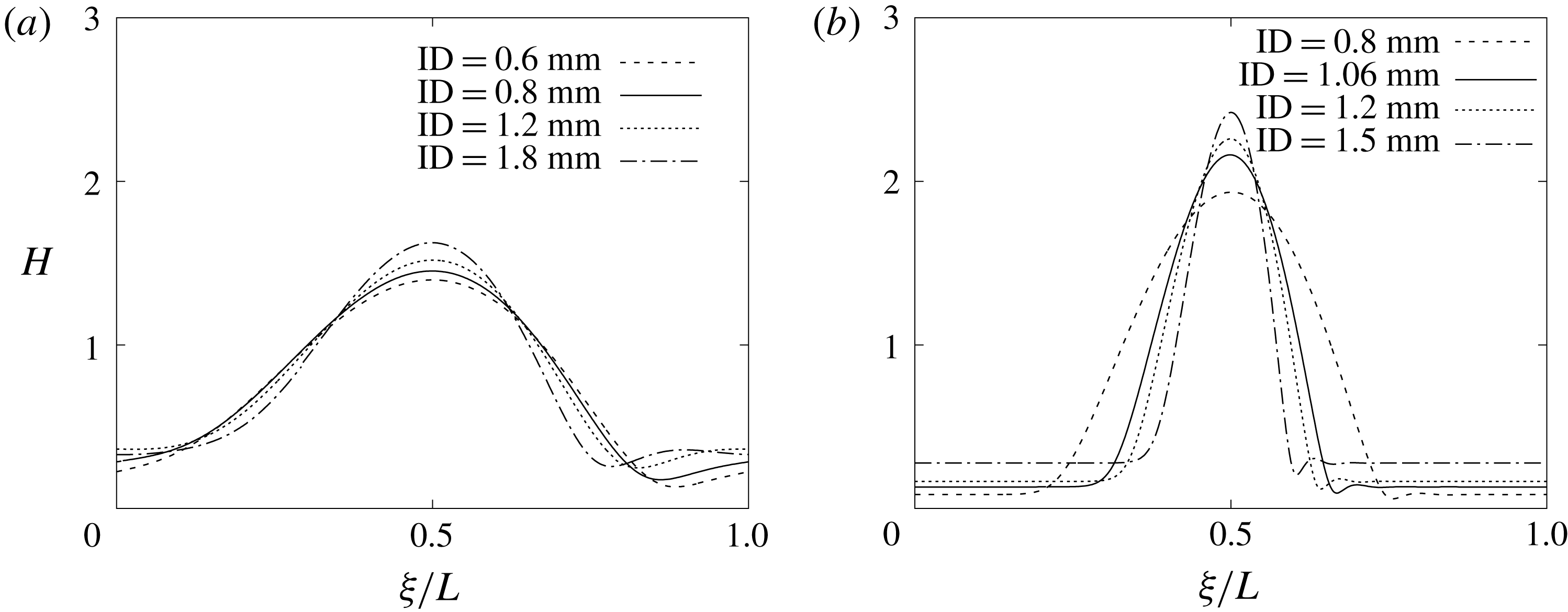
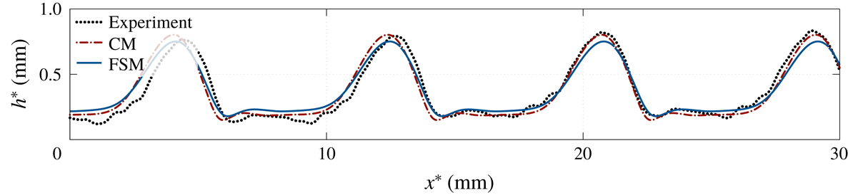
Figure 7 shows the different morphologies that arise when using a thick fibre versus a thin fibre. In the former case, the droplet height and width are close to the period length. In the latter case, the droplets appear more isolated. The profiles in figure 8 illustrate a direct comparison between the profiles predicted by both models, which are within the margin of error from the experimental film thickness.
Plots of rescaled travelling wave solutions
 $H(\unicode[STIX]{x1D709})$
obtained from (3.14) using
 $(L,M_{0})$
from experiments at flow rate
 $Q_{m}^{\ast }=0.04~\text{g}~\text{s}^{-1}$
and (a) thick fibre of radius
 $R^{\ast }=0.215~\text{mm}$
and (b) thin fibre of radius
 $R^{\ast }=0.1~\text{mm}$
, corresponding to different nozzle inner diameters (
 $ID$
). The slip length is set to be
 $\unicode[STIX]{x1D706}^{\ast }=7~\unicode[STIX]{x03BC}\text{m}$
.

Film thickness comparison between experiment and theory, for fibre size
 $R^{\ast }=0.215~\text{mm}$
, flow rate
 $Q_{m}^{\ast }=0.04~\text{g}~\text{s}^{-1}$
and nozzle inner diameter
 $ID=3.0~\text{mm}$
.

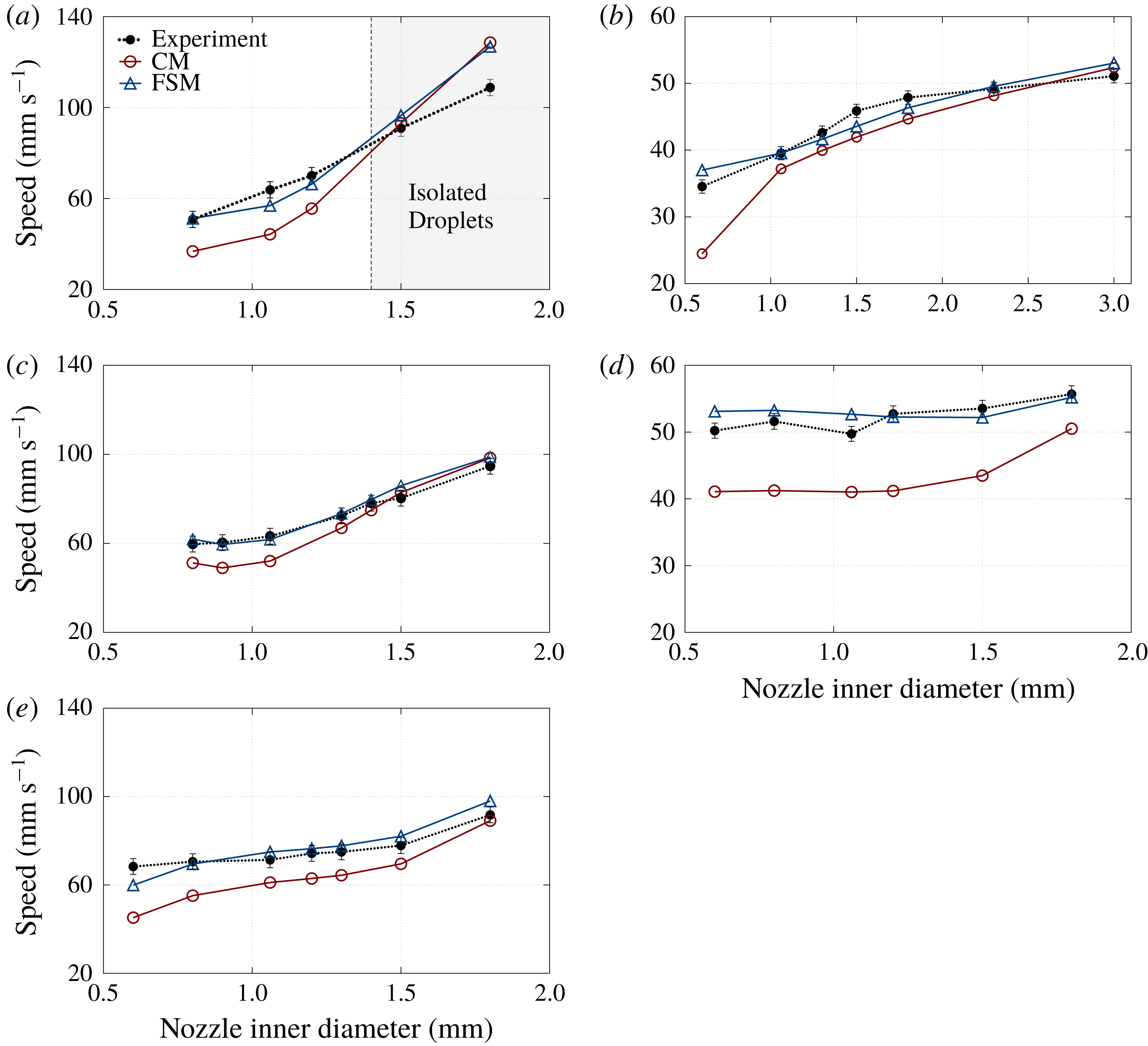
Average bead speed for fibre radius
 $R^{\ast }=0.1~\text{mm}$
(a,c,e) and
 $R^{\ast }=0.215~\text{mm}$
(b,d), and flow rates
 $Q_{m}^{\ast }=0.04$
(a,b), 0.06 (c,d) and
 $0.08~\text{g}~\text{s}^{-1}$
(e), compared to the proposed model (FSM) as blue diamonds and Craster & Matar (CM) as red circles. The last two data points in (a) are in the isolated droplet regime. There is no plot for
 $R^{\ast }=0.215~\text{mm}$
,
 $Q_{m}^{\ast }=0.08~\text{g}~\text{s}^{-1}$
, because in this case there is no TWS and the experiments lie in the convective regime.

The predicted speeds, however, have noticeable differences between the two models. In figure 9, we show plots of the observed and predicted speeds for varying nozzle sizes. The left panels indicate the thin fibre
 $R^{\ast }=0.1~\text{mm}$
whereas the right panels illustrate the thick fibre
 $R^{\ast }=0.215~\text{mm}$
, with the flow rate
 $Q_{m}^{\ast }$
increasing from top to bottom. The FSM model agrees quite well with the experimental observations across all of the data. In contrast, the CM model underestimates the speed. We do not show the case with the fibre radius
 $R^{\ast }=0.215~\text{mm}$
and the flow rate
 $Q_{m}^{\ast }=0.08~\text{g}~\text{s}^{-1}$
, because under those conditions the flow is in the convective regime and the bead speed cannot be uniquely defined. We note that for the FSM model, we choose
 $\unicode[STIX]{x1D716}_{p}^{\ast }$
to be 0.12 mm for the fibre of radius
 $R^{\ast }=0.1~\text{mm}$
, and
 $\unicode[STIX]{x1D716}_{p}^{\ast }=0.215~\text{mm}$
for the fibre of radius
 $R^{\ast }=0.215~\text{mm}$
.
Note in figure 9(a), the RP regime transitions to the isolated droplet regime, where the TWS is unstable and both models overpredict the speed, as expected. The following section discusses this transition in detail.
5.2 Regime transition
The emergence of instabilities in the thin liquid films between travelling droplets characterizes the transition from the RP regime to the isolated droplet (IS) regime. Guided by the stability analysis from § 4, we can explore these instabilities and the departure from the RP regime as the nozzle diameter varies. The IS regime gives rise to time-periodic dynamics that cannot be captured by the travelling wave solutions of (4.8). In this case, we need to solve the fully time-dependent model (3.14). The numerical solution and the experimental observation from the IS regime are plotted in figure 10(b). In contrast, the travelling wave solution for an RP experiment (
 $ID=0.8~\text{mm}$
) is plotted in figure 10(a). Our dynamic simulation captures a difference in the advancing and receding lines of the droplets, even though this difference is more pronounced in the experiment.
Experiments (black top halves) with parameters
 $R^{\ast }=0.1~\text{mm}$
,
 $Q_{m}^{\ast }=0.04~\text{g}~\text{s}^{-1}$
against the FSM (bottom halves) showing (a) the RP regime with nozzle
 $ID=0.8~\text{mm}$
and (b) the isolated droplet regime with nozzle
 $ID=1.8~\text{mm}$
.

The nonlinear PDE (3.14) was solved numerically using a fully implicit second-order finite difference method. Figure 11 shows the dynamics starting from a widely spaced travelling wave solution obtained from the ODE (4.8) with a small perturbation,
 $h_{0}(x)=H(x)+0.001\unicode[STIX]{x1D6F9}(x)$
. This simulation corresponds to the IS regime experiment with the fibre radius
 $R^{\ast }=0.1~\text{mm}$
, flow rate
 $Q_{m}^{\ast }=0.04~\text{g}~\text{s}^{-1}$
and the nozzle diameter
 $ID=1.8~\text{mm}$
. It demonstrates the effects of the unstable eigenmodes shown in figure 6(b). Such instabilities lead to interesting spatio-temporal pattern formation with small droplets appearing from the unstable long flat film between the large travelling beads.
Dynamic simulation showing the development of instabilities in the isolated droplet regime for parameters
 $R^{\ast }=0.1~\text{mm}$
,
 $Q_{m}^{\ast }=0.04~\text{g}~\text{s}^{-1}$
and nozzle size
 $ID=1.8~\text{mm}$
.

PDE simulations for (a) the FSM model (3.14) with
 $\unicode[STIX]{x1D716}_{p}^{\ast }=0.12~\text{mm}$
and (b) the CM model starting from
 $h_{0}(x)=H(x)$
with identical
 $(M_{0},L)$
and small perturbations, showing that the TWS to the FSM model is stable in time, while the one for the CM model is unstable and converges to a time-periodic solution at long times. The
 $(M_{0},L)$
values are obtained from the experiment with fibre radius
 $R^{\ast }=0.1~\text{mm}$
, flow rate
 $Q_{m}^{\ast }=0.04~\text{g}~\text{s}^{-1}$
and nozzle
 $ID=1.2~\text{mm}$
.

Plots of
 $\max (h^{\ast })$
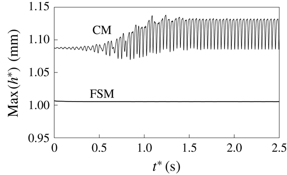
in time for the PDE simulations shown in figure 12.

The film stabilization model (FSM) correctly captures the bifurcation from the RP regime to the IS regime as the nozzle diameter increases. For small fibre size
 $R^{\ast }=0.1~\text{mm}$
at
 $Q_{m}^{\ast }=0.04~\text{g}~\text{s}^{-1}$
, experiments show that the regime transition occurs between nozzle inner diameters 1.2 mm and 1.5 mm (see figure 9
a). However, the CM model predicts the transition between 0.8 mm and 1.06 mm, contradicting experimental observations. That is, based on stability analysis, the travelling wave solutions of the CM model are unstable for all nozzles bigger than 0.8 mm. For example, for the case of the nozzle diameter
 $ID=1.2~\text{mm}$
, figure 12 shows a comparison of dynamic simulation results of the CM and the FSM models. The travelling wave in the FSM model propagates steadily with a constant speed and profile (see the bottom curve in figure 13). In contrast, the CM model simulation shows that the initially nearly flat coating layer quickly evolves into small waves ahead of the major sliding bead. As the major bead interacts with the small waves downstream, the maximum height of the film thickness oscillates in time (see the top curve in figure 13) since the main bead gains mass from these smaller waves. The dynamic solution eventually converges to a time-periodic solution that describes the case in the isolated droplet regime. A similar bifurcation occurs when keeping the nozzle diameter constant,
 $ID=1.8~\text{mm}$
, and changing the flow rate (not shown here). Again, just the FSM model correctly predicts regime transition between
 $Q_{m}^{\ast }=0.050~\text{g}~\text{s}^{-1}$
and
 $Q_{m}^{\ast }=0.055~\text{g}~\text{s}^{-1}$
, which agrees with experimental measurements. For larger fibre size
 $R^{\ast }=0.215~\text{mm}$
, both models produce a stable travelling wave for all nozzle sizes shown in figure 9, i.e. there is no isolated phenomenon predicted.
5.3 The effects of slip and curvature
We next study how the slip length
 $\unicode[STIX]{x1D706}$
affects the flow characteristics under the slip model (SCM). It has been shown in Halpern & Wei (Reference Halpern and Wei2017) that the presence of slip enhances capillary instability and promotes both droplet formation and the speed of the falling drops. Similar observations are also made in our study of travelling wave solutions for given
 $(L,M_{0})$
in figure 14. We observe that, compared with the no-slip case, the slip cases (
 $\unicode[STIX]{x1D706}\neq 0$
) have taller and narrower droplets. The dependence of the speed
 $c$
on the slip length
 $\unicode[STIX]{x1D706}$
in figure 14(b) agrees with the observation in Halpern & Wei (Reference Halpern and Wei2017). The speed of travelling wave solutions is of order
 $O(1)$
in the weak slip limit and grows linearly with
 $\unicode[STIX]{x1D706}$
in the strong slip limit. Since typical slip length
 $\unicode[STIX]{x1D706}^{\ast }$
is
 $1{-}10~\unicode[STIX]{x03BC}\text{m}$
for silicone oil, and typical Nusselt film thickness
 ${\mathcal{H}}$
is approximately 0.5 mm in our experiments, our experimental conditions are expected to be in the weak slip limit.
Travelling wave solutions of (4.8) for the SCM model with a varying slip length
 $\unicode[STIX]{x1D706}=0,0.05,0.1,1$
for
 $(L,M_{0})=(4.94,8.27)$
showing that (a) larger slip yields larger droplet heights and thinner precursor layers and (b) in the weak slip limit the moving speed of drops is
 $O(1)$
, and the speed increases linearly with slip length in the large slip limit.

A comparison of travelling wave solutions to (4.8) from the original Craster & Matar model (CM), the Slip Craster & Matar model (SCM), the Full curvature model (FCM) and the experimental observation showing that, while the solution profiles from each model are close, the estimated bead velocity predicted by the FCM matches the best with the experimental result. The bead profile is obtained from the thick fibre experiment with
 $R^{\ast }=0.215~\text{mm}$
, flow rate
 $Q_{m}^{\ast }$
 $=0.04~\text{g}~\text{s}^{-1}$
and the inner nozzle diameter
 $ID=1.06~\text{mm}$
. The corresponding non-dimensional constraints are given by
 $(L,M_{0})=(4.94,8.92)$
.

Average bead speed obtained from experiments with
 $R^{\ast }=0.1~\text{mm}$
and
 $Q_{m}^{\ast }=0.06~\text{g}~\text{s}^{-1}$
, compared to the speed predicted by the original CM model, the SCM model with
 $\unicode[STIX]{x1D706}^{\ast }=3~\unicode[STIX]{x03BC}\text{m}$
, and the FCM model with
 $\unicode[STIX]{x1D706}^{\ast }=3~\unicode[STIX]{x03BC}\text{m}$
.

Similar to the slip model, the inclusion of the fully nonlinear curvature term in the FCM model with
 ${\mathcal{Z}}(h)$
given by (3.18) also increases the moving speed of sliding droplets. Figure 15 shows a comparison of the experimental bead profile against those obtained from the Craster & Matar model (CM), the slip model (SCM) with the linear azimuthal term in (3.16), and the Full curvature model (FCM) with the full azimuthal curvature term in (3.18). Under the period and mass constraint, whereas the different models all yield solution profiles similar to the experimental result, the predicted speed obtained from the ODE (4.8) is increased when the slippage effects and full curvature term are included, and the FCM model with the slip length
 $\unicode[STIX]{x1D706}^{\ast }=7~\unicode[STIX]{x03BC}\text{m}$
provides the best agreement with the experiment.
While the slip and the full curvature do influence predicted wave propagation velocities, their corrections alone are not sufficient to improve agreement with the experimental data. Figure 16 shows that, for the thin fibre case (
 $R^{\ast }=0.1~\text{mm}$
), the CM and SCM models underestimate the bead velocities for all nozzle sizes. Even though the FCM model yields a good agreement with the experiment for small nozzles, it overestimates the speed for large nozzles. Similar trends are observed for the thick fibre case (
 $R^{\ast }=0.215~\text{mm}$
) (not shown here). In these cases, the film stabilization term becomes vital for correctly predicting speeds and the regime transition, as discussed in § 5.1.
6 Conclusion
We have performed a thorough study of viscous flow down vertical fibres, comparing a range of experimental results to different models of interest. We focus on understanding the Rayleigh–Plateau (RP) regime, where travelling wave solutions emerge, and its transition to the isolated droplet (IS) regime due to nozzle effects. We propose a full model that incorporates the stability of thin uniform layers by including a film stabilization (FSM) term to the pressure. In this paper, experiments are compared to versions of a lubrication model, showing the influences of slip effects, nonlinear azimuthal curvature and the FSM term on predicted bead velocities and film profiles. In addition, we perform a stability analysis of the travelling wave solutions (TWS) that confirms the importance of the FSM term to properly capture regime transitions. The model equations lead to both closely spaced wavy solutions and widely spaced droplet solutions which are affected by different fibre sizes, flow rates and nozzle geometry. The slip model (SCM) leads to an increased speed of propagation and promotes formation of droplets. The Full curvature model (FCM) also increases the magnitude of the bead velocity, while the FSM model stabilizes the thin undisturbed layer between consecutive droplets, which leads to a more accurate speed prediction. Our results show outstanding experimental agreement using the FSM’s TWS in the RP regime. In the isolated droplet regime, dynamic simulations of widely spaced droplet solutions agree very well with experiments.
For future work, we are interested in the nozzle effects on the global modes (Duprat et al. Reference Duprat, Ruyer-Quil, Kalliadasis and Giorgiutti-Dauphiné2007) of the absolutely unstable flows in RP and IS regimes. Of particular interest would be the selection of spacing between moving beads with a given nozzle diameter. Duprat et al. (Reference Duprat, Ruyer-Quil and Giorgiutti-Dauphiné2009) investigated the spatial response of a film flowing down a fibre to inlet forcing using a system of coupled equations for the flow rate and the film thickness. We anticipate that a similar model can be used to study the nozzle effects. Moreover, the nozzle effects in our experiments are also related to the dripping faucet problem (Dreyer & Hickey Reference Dreyer and Hickey1991; Coullet, Mahadevan & Riera Reference Coullet, Mahadevan and Riera2005), which studies the chaotic behaviour of a dripping faucet. Motivated by these theories, in the future we would like to further study the connection between the fluid dynamics near the nozzle and its influence on the downstream flow transitions.
In addition, our experimental observations with different fluids, not published here, show that the nonlinear dynamics can change quite drastically, and choosing the appropriate coating thickness
 $\unicode[STIX]{x1D716}_{p}^{\ast }$
is an interesting question for further study. For
 $\unicode[STIX]{x1D716}_{p}^{\ast }$
of the same order as the fibre radius, the value of the stabilization parameter
 $A^{\ast }$
is between
 $10^{-11}$
and
 $10^{-12}~\text{N}~\text{m}$
, which is much larger than typical values of Hamaker constant between
 $10^{-19}$
and
 $10^{-21}~\text{N}~\text{m}$
. This indicates that the film stabilization term in our model is stronger than typical van der Waals interactions, and the underlying physics still needs future investigation.
Acknowledgements
This work was supported by the Simons Foundation Math+X investigator award number 510776 and the National Science Foundation under grant CBET-1358034.
Appendix A. Nomenclature
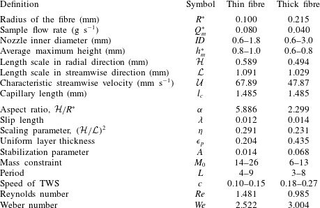
In table 2, we show the relevant nomenclature and the corresponding values given a sample flow rate for thin and thick fibres. The first portion of the table shows dimensional parameters and their units, while the bottom part of the table shows the selected non-dimensional scales.
Nomenclature and their sample values.

Appendix B. Nozzle effects
Motivated by the different regimes shown in figure 9, we review the details of the dependence of bead speeds on its spacing and mass constraint, and their relations to the nozzle diameters. It has been empirically shown in Sadeghpour et al. (Reference Sadeghpour, Zeng and Ju2017) that, when other experimental parameters are fixed, the nozzle diameter determines the spacing and mass constraint for the travelling beads. Typical ranges for the mass constraint and period with increasing nozzle inner diameter are shown in table 2.
(a) The experimentally measured relations between the dimensional
 $L^{\ast }$
,
 $M_{0}^{\ast }$
and the nozzle inner diameters for fibre radius
 $R^{\ast }=0.215~\text{mm}$
at flow rate
 $Q_{m}^{\ast }=0.04~\text{g}~\text{s}^{-1}$
. (b) The predicted speed of travelling wave solutions to the film stabilization model (FSM) in comparison with the corresponding experimental results (large dots) with varying
 $M_{0}^{\ast }$
and
 $L^{\ast }$
.

The plot in figure 17(b) shows the travelling wave speeds parametrized by a range of values for the dimensional period
 $L^{\ast }$
to examine the impact of large versus small bead spacings. We also use a range of values for
 $M_{0}^{\ast }$
to study the influence of bead sizes on its velocity. For each calculation with a given dimensional
 $(L^{\ast },M_{0}^{\ast })$
, the numerically obtained travelling wave speed from the film stabilization model is labelled by a small dot. For a fixed fibre radius at a given flow rate, the diameter of the nozzle feeding the fluid selects the
 $(L^{\ast },M_{0}^{\ast })$
pair. To illustrate this connection, figure 17(b) shows the experimental travelling bead velocities in large dots, for different nozzle sizes which correspond to specific
 $(L^{\ast },M_{0}^{\ast })$
pairs. These results refer to experiments with fibre radius
 $R^{\ast }=0.215~\text{mm}$
at flow rate
 $Q_{m}^{\ast }=0.04~\text{g}~\text{s}^{-1}$
, and the measured relations between
 $L^{\ast },~M_{0}^{\ast }$
and the nozzle inner diameter are shown in figure 17(a). The nozzle diameter ranges from 0.6 mm to 3.0 mm. The period
 $L^{\ast }$
and the mass
 $M_{0}^{\ast }$
both increase as the nozzle diameter increases, and the predicted travelling wave speeds show good agreement with the experimental results.