Introduction
Injuries and deterioration of native musculoskeletal tissues due to trauma, congenital factors, and aging have been shown to affect the quality of human life psychologically and physically.Reference Langer and Vacanti1, Reference Risbud2 This has led to the affected individuals’ inability to perform their daily activities. The injured or damaged sites can be soft tissues such as tendons, ligaments, and cartilages, hard tissues (bones), or a combination of both (e.g., osteochondral sites and maxillofacial tissues). The constituents of the native tissues, in general, are highly organized in a unique manner so that they can execute their specific functions.Reference Saltzman3, Reference Shier, Butler and Lewis4 Hence, under circumstances where the anatomical organization is disrupted and natural recovery with or without drug-based treatments or physical therapies are ineffective, surgical options such as autologous grafts, allogeneic grafts, and tissue engineering (TE) scaffolds serve as viable substitutes to restore tissue functions.Reference Griffith and Swartz5, Reference Vang6
In recent decades, TE, the application of principles of engineering and life sciences toward the development of biological substitutes that restore, maintain, or improve tissue function or a whole organ, has emerged to play an interdisciplinary role in the design and development of tissue replacements.Reference Langer and Vacanti1–Reference Lysaght9 The principles of TE application or regenerative medicine serve to eliminate the drawbacks of autologous and allogeneic transplantation, which include donor site deterioration, transplant rejection, and delayed/or inconsistent restoration outcomes of the repaired tissue.Reference Yeong, Chua, Leong and Chandrasekaran10–Reference Ma12 TE constructs, on the other hand, provide functional healing of the affected tissue site by providing the necessary structural and biological supports. With the progression toward using additive manufacturing (AM) or rapid prototyping (RP) technology and organ printing for tissue scaffold fabrication, the recovery duration for each patient is significantly reduced.Reference Bartolo, Chua, Almeida, Chou and Lim13–Reference Yang, Leong, Du and Chua16 Particularly, AM techniques such as selective laser sintering (SLS), fused deposition modeling (FDM), and three-dimensional printing (3DP)Reference Tan, Chua, Leong, Cheah, Cheang, Abu Bakar and Cha17–Reference Simpson, Wiria, Amis, Chua, Leong, Hansen, Chandrasekaran and Lee21 allowed for the construction of tissue scaffolds, which catered to the patient’s specific needs.Reference Peltola, Melchels, Grijpma and KellomÃki22, Reference Naing, Chua, Leong and Wang23 Such applications of AM technology for TE have become increasingly common over recent years due to (1) its ease of operation, (2) its ability to translate a patient’s scanned image to a computer-aided design (CAD) model, and (3) the possibility of automating the CAD generation process for scaffold customization.Reference Naing, Chua, Leong and Wang23–Reference Cheah, Chua, Leong, Cheong and Naing25 Existing literature on AM technology for TE applications has encouraged tissue engineers to develop advanced solutions for anatomically customized tissues, which has resulted in the evolution of functional TE scaffolds.Reference Hollister26 The enhancements made to AM technology include the introduction of nano-sized features for effective cell guidanceReference Duan, Wang, Zhou and Cheung27–Reference Comesaña, Lusquiños, del Val, López-Álvarez, Quintero, Riveiro, Boutinguiza, de Carlos, Jones, Hill and Pou32 and scaffold design optimization to provide the essential mechanical and biological properties for faster restoration of tissue function.Reference Hollister26, Reference Baino and Vitale-Brovarone33–Reference Singh, Berkland and Detamore35
Currently, scaffold design optimization has been identified as one of the key components toward achieving functional TE constructs. The optimization strategies have been carried out either by directly using AM techniques or through automated CAD-based models. The AM methods applied include fiber-based deposition or extrusion and particle-bonding techniques. In general, the resultant scaffolds obtained from these techniques exhibited controlled pore size gradient or structural anisotropy, which served to mimic the targeted tissue’s anatomical geometry and to achieve mechanical characteristics that meet the mechanical requirements of the affected tissue. FDM and in-house fiber deposition systems have shown promising potential in the production of functional TE scaffolds.Reference Zein, Hutmacher, Tan and Teoh36–Reference Liu, Xiong, Yan, Zhang, Wang and Jin38 These techniques, which melt and extrude material through a nozzle, have also shown improved cell proliferation and seeding efficiency under in vitro culture conditions compared to conventional tissue engineering methods.Reference Ozkan, Kalyon and Yu39, Reference Sobral, Caridade, Sousa, Mano and Reis40 However, the control of porosity was achieved by different 2D lay-down patterns and the rapid solidification of the extruded fibers that form the tissue constructs and often provide insignificant surface roughness for cell attachment and neo-vascularization.Reference Yeong, Chua, Leong and Chandrasekaran10 Although particle-bonding techniques such as SLS and 3DP are preferred AM approaches for incorporating CAD models with highly complex architecture,Reference Tan, Chua and Leong41, Reference Yeong, Chua, Leong, Chandrasekaran and Lee42 minimal studies have been conducted on producing scaffolds with a porosity gradient. Present studies associated with particle-bonding methods for the fabrication of functional TE scaffolds are limited to the variation of particle size and material proportions within the constructs.Reference Sherwood, Riley, Palazzolo, Brown, Monkhouse, Coates, Griffith, Landeen and Ratcliffe43, Reference SalmoriaI, Ahrens, KlaussI, PaggiI, OliveiraI and Lago44 In contrast to 3DP and fiber deposition techniques, SLS, which operates by selectively sintering thin layers of powder using a carbon dioxide laser beam to form 3D scaffolds (see the article by Duan and Wang in this issue), offers more advantages such as a wider range of processing materials without the use of toxic solvents.Reference Duan, Wang, Zhou and Cheung27–Reference Duan, Cheung and Wang29, Reference Wiria, Leong and Chua45
The early phase of automated CAD modeling facilitates the assembly of tissue primitives, also known as building blocks or unit cells, to form 3D TE constructs.Reference Chua, Leong, Cheah and Chua46–Reference Chua, Leong, Cheah and Chua50 The choice of tissue primitive is dependent on the intended function of the native tissue, and significant effort is needed to ensure the integrity of the interfaces between identical or dissimilar primitives chosen to build the construct.Reference Wettergreen, Bucklen, Sun and Liebschner51 However, these elementary CAD approaches, in combination with AM systems, will eventually produce tissue constructs with a porosity profile different from that of the native tissue and lead to compromising desirable mechanical characteristics. This therefore led to the emergence of CAD-based functional TE strategies, which aim to achieve CAD models, and subsequently 3D builds, which replicate the anatomical geometry and/or the mechanical properties of the native tissue. One of the strategies included the computational assessment of the desired microstructure using finite element analysis to obtain a tissue scaffold and regenerated tissue with effective stiffness that matches that of the native bone tissue.Reference Hollister, Maddox and Taboas52 The evaluated 3D physical builds were produced to verify its dimensional and mechanical resemblance to the native tissue, and further work was conducted to include the effects of biodegradability.Reference Adachi, Osako, Tanaka, Hojo and Hollister53 Another area of CAD-based functional TE was focused solely on mimicking the topology of the native tissues.Reference Schroeder, Regli, Shokoufandeh and Sun54–Reference Cai and Xi57
Current literature on scaffold design optimization has indeed provided great insight into functional TE. Nevertheless, the integration of the most suitable AM method and automated CAD models remain a major challenge in functional TE. This area is particularly important in bone TE since the anatomical geometry of bone is often described as having varied pore size distribution and varying mechanical properties in the radial direction.Reference Khoda, Ozbolat and Koc58, Reference Sudarmadji59 Thus, this work presents a computational model of a functionally graded scaffold (FGS) followed by the fabrication of a replacement femur bone segment model that meets both the geometrical and mechanical requirements of an osseous tissue.
Process flow of design automation for a radial FGS system
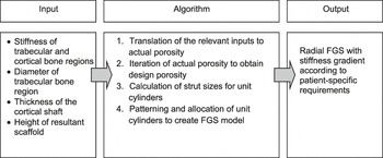
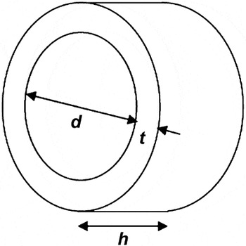
A general overview of the radial FGS system is presented prior to a detailed discussion on yielding the tissue scaffolds with desirable physical and mechanical properties. Human bone tissues can be differentiated into trabecular and cortical bone, which play significantly different roles in essential nutrient transportation and supporting physiological loadings, respectively.Reference Freeman and Rylander60, Reference Sudarmadji, Tan, Leong, Chua and Loh61 Similarly, soft tissues such as cartilage require zonal variations for the entrapment of chondrocytes (cells in cartilage), secretion of the tissue-specific extracellular matrix (ECM), and finally the formation of the neo-cartilage tissue.Reference Klein, Malda, Sah and Hutmacher34 The development of the radial FGS concept in this study aims to provide an effective anatomical environment for the biological and functional recovery of injured or damaged musculoskeletal tissues. The objective of the FGS approach is focused on the computational generation of bone tissue constructs with a stiffness gradient that mimics natural bones. The radial FGS model, which encompasses design automation, consists of three distinct steps: (1) input, (2) algorithm process, and (3) output (Figure 1). The input section involves the definition of the required parameters for the subsequent algorithm processing step. The inputs are the stiffness of the cortical and trabecular bone, the diameter of the trabecular bone (d), the thickness of the cortical bone (t), and the desired height of the resultant tissue scaffold (h) (Figure 2). These parameters are specifically derived from a patient’s native tissue, therefore leading to the possibility of customized tissue constructs. Following the input section, the data are translated to achieve the desired porosity of the fabricated scaffolds based on an established stiffness-porosity relationship. The varied pore size distribution, as displayed in native tissues, is achieved by the manipulation of the dimensions of the unit cells comprising the different bone regions.
A flowchart presenting the automated functionally graded scaffold process.

A schematic representation of the trabecular bone diameter (d), cortical shaft thickness (t), and scaffold height (h).

Briefly, as the design porosities are computed, the program will begin with the generation of the trabecular region using unit cylinders (or unit cells) that are arranged systematically in a concentric manner. The addition of unit cylinders will continue until the desired trabecular bone diameter is met. Unit cylinders of an appropriate size were then added to the outermost concentrically arranged ring, which closely corresponds to the porosity of the cortical region. The addition of the cortical rings is halted upon achieving the desired scaffold thickness. The series of concentric rings are duplicated and stacked on top of each other axially until the required scaffold height is reached. Finally, the output section presents a radial FGS with both cortical and trabecular stiffness variation that mimic the targeted native bone tissue. The FGS can be further processed to replicate the overall shape of the bone tissue.
Parameters and properties of the unit cylinder
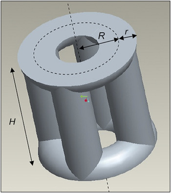
The bone tissue scaffolds in the present study are composed of concentric rings of unit cylinders (unit cells), with varying geometrical features according to the calculated design porosity. Each unit cylinder is comprised of four vertical cylindrical struts, with their ends connecting to two halves of a torus (Figure 3). In order to calculate the effective strut size for each unit cylinder, three parameters must be defined: the distance between the axis of the unit cylinder and the center of the torus tube (R), the radius of the torus tube (r), and the height of the unit cylinder (H). The radii of the cylindrical struts are the same as r.
A unit cylinder and its defining parameters. Center of the torus tube, R, the radius of the torus tube, r, and the height of the unit cylinder, H.

The volume of each unit cylinder has to be first formulated in order for the theoretical derivation of the design porosity. Considering the elementary torus and cylindrical strut units within the unit cylinder, the volume can be expressed as:

where V ht = volume of a half torus = π2 · R · r 2
V s = volume of a cylindrical strut = π · r 2 · H
V i = volume of an intersection between the strut and the torus.
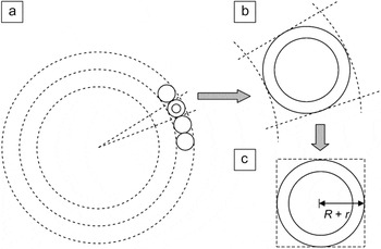
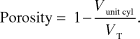
The unit cylinders are arranged spatially to form concentric rings (Figure 4a), and the porosity of individual unit cylinder can be estimated to be:
Schematic of (a) unit cylinders arranged in a concentric manner, (b) a magnified unit cylinder, and (c) the approximated square section surrounding a unit cylinder.

The total volume V T is described as the apparent volume of one concentric segment. To simplify the theoretical calculations, the cross-section of the concentric segment is approximated to a square section closely bound to the circular cross-section of the unit cylinder (Figure 4b and 4c). The width of the square section is thus defined to be 2(R + r), and V T can be expressed as:

Stiffness-porosity relationship for polycaprolactone scaffolds fabrication via SLS
PCL was selected as the material for the SLS (Sinterstation 2500) manufacturing method owing to its biocompatibility, biodegradability, and ability to blend with other polymers or ceramics to induce a desirable rate of new bone formation.Reference Tan, Chua, Leong, Cheah, Gui, Tan and Wiria19, Reference Leong, Chua, Gui and Verani63, Reference Wiria, Leong, Chua and Liu64 In this study, PCL powder (CAPA 6501, Solvay Interox Pte Ltd., UK), with an average particle size of 100 μm, was used to fabricate the scaffolds with overall dimensions set to 25.4 × 25.4 × 12.7 mm3. The CAD-based scaffolds consisted of unit cylinders with values of r varying between 0.6 to 1 mm, while R was kept constant at 1 mm. The manipulation of the r values was aimed at achieving three porosities for the stiffness-porosity relationship, namely 40%, 60%, and 80%.Reference Sudarmadji59, Reference Sudarmadji, Tan, Leong, Chua and Loh61 The compressive properties of fabricated PCL scaffolds were obtained using an Instron 5569 Universal Tester with testing conditions, according to the American Society for Testing and Materials (ASTM D 1621-04a), and the experiment was limited to a maximum compression of up to 60% strain. The compressive stiffness was evaluated from the stress-strain curves obtained. The derivation of the stiffness-porosity relationship has been previously discussed,Reference Sudarmadji, Tan, Leong, Chua and Loh61 however, without the inclusion of the unit cylinders as unit cells for the assembly of the scaffold model. In this case, the compressive stiffness of the scaffold was found to be inversely proportional to its individual porosities (data not shown). The linear stiffness-porosity relationship will facilitate the prediction of the actual porosity upon the input of stiffness and can be expressed asReference Sudarmadji, Tan, Leong, Chua and Loh61

where E * = compressive stiffness of the unit cylinder scaffold
CF = correction factor that is unique to the unit cylinder configuration
EPCL = bulk modulus of PCL
V p = porosity of the unit cylinder scaffold.
Thus, with E * known, the porosity of the FGS scaffold and the appropriate strut sizes (r) of the unit cylinders can be computed for the trabecular and cortical regions, respectively.
Algorithm for automated radial FGS systems
Definition of critical parameters for the formation of concentric layers using circles of uniform diameter
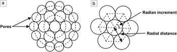
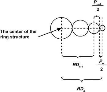
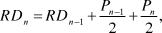
The primary phase of the FGS model involves the definition of the relevant parameters as well as the establishment of relationships between these parameters. In the process, the unit cells are represented by circles in two dimensions instead of unit cylinders for clearer illustration. The first concentric ring of circles is formed by allocating the circular models around the initial circle (center in Figure 5). All circles are identical in size, and the patterning or positioning of the unit cells is strictly referenced to the center of the initial circle; the centers of the circles of the first concentric ring are equidistant from the center of the initial circle. Together, the centers of the initial circle and the center of the circles of the first ring form a regular N-sided polygon, as seen in Figure 5. The number of vertices in the regular polygon (N) also refers to the number of unit cells (circle) at that particular ring. In addition, four sets of physical parameters shall be frequently discussed in this section: the diameter of the circle (P), radial distance (RD), radian increment—the angle formed between the connecting center lines of adjacent circles in the same concentric ring (θ), and the number of circles within a particular concentric ring (N). The relationships among these parametric constituents are important to the generation of resultant tissue scaffold structure. RDn is the distance between the center of the initial circle and the center of the circle at the n th ring (Figure 6) and is defined as
Schematic illustrating (a) the circular unit cells assembled in concentric rings and (b) the formation of an N-sided polygon within the first concentric ring.

A diagram indicating the relevant physical parameters.

where RDn = radial distance of circles within the n th ring
RDn –1 = radial distance of circles within the (n–1)th ring
Pn– 1 = diameter of circles within the (n–1)th ring
Pn = diameter of the circles within the n th ring.
The radian increment is formulated using trigonometric principles. Using polar coordinates, the position of each circle is specified. The radian increment to achieve the n th concentric layer θn can be expressed based on the following equation:
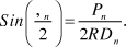
The number of circular unit cells at the n th ring Nn can then be defined as:

Equation 7 takes into account that values of θn that give a non-integer Nn would result in void formation within the ring. Thus, the resultant Nn will be rounded up or down, depending on the TE requirements. In the condition where Nn was replaced with a nearest integer of a higher value, it would result in a decrease in the size of the circles and vice versa. The methodology for the arrangements of the unit circular cells, which will be replaced with unit cylinders, shall be elaborated algorithmically in the following section. Note that for the unit cylinders, the change in the total diameter of a cylinder for one concentric ring (Pn in the 2D illustration in this section) as compared to that of the next ring (P n–1) is achieved by changing r, while R is kept constant.
Procedural illustration of the automated radial FGS system
The circular unit cells from the previous section can be extended to the unit cylinders to demonstrate the porosity change with respect to the transition between the trabecular and cortical regions. The concentric arrangements of the unit cylinders originate from the initial unit cylinder leading to the formation of structural features that resemble the trabecular region. The strut size of the unit cylinder r can be obtained based on the stiffness-porosity relationship, as highlighted in the previous section, while the torus radius R is kept constant. The outer concentric rings were subsequently allocated with unit cylinders that matched the physical properties of the cortical bone region upon reaching the desired trabecular diameter. Similarly, the value of r assigned to the unit cylinders, which form the cortical bone, is derived based on the established structural-mechanical correlation.
The resultant radial FGS model is ultimately presented in the form of a 3D cylinder consisting of unit cylinders with varying structural properties. The computational construction of the FGS begins with the formation of the default unit cylinder, otherwise known as the trabecular ring 0. As the value of r is calculated according to the stiffness-porosity relationship, the total diameter of the unit cylinder, Dc 0, is defined as:

where the radius of the torus R in the unit cylinder is kept constant at 1 mm for all the unit cylinders used in the FGS model. The height of the unit cylinder H 0 is assigned to be the same as Dc 0 and is consistent throughout the 3D FGS configuration. The number of axially stacked layers of rings L is defined by  . The overall diameter of ring 0, Dr 0, is the same as Dc 0. Finally, the overall diameter of the 3D FGS cylindrical structure with n rings Drn is expressed as

For ease of implementation, L and H 0 are set to be identical for all subsequent concentric rings. The duplication and stacking of concentric rings along the axis is halted when H 0 reaches or exceeds the input desired scaffold height (h). It should also be noted that Equation 4 is important for controlling the dimensions of the trabecular and cortical regions by determining an optimum value of r. The FGS system will proceed with the addition of concentric rings until the required overall diameter is met.
The continuation of the above algorithmic set involved the location and patterning of unit cylinders within the next concentric ring, for convenience, named trabecular ring 1. Since trabecular ring 1 is generated based on the trabecular bone properties, the total diameter of the unit cylinders within this ring, Dc 1, will be equivalent to Dc 0. The overall diameter of the 3D FGS cylindrical structure consisting of trabecular ring 0 and ring 1 is then computed and stored.
The issue of void formation must be addressed as the addition and patterning of unit cylinders progresses to the trabecular ring 2. This is because a non-integer N 2 value is encountered, and thus further computation is required to introduce a few assumptions and a series of iterations. The implementation of the algorithm is explained in the next section.
Trabecular ring 2—Assumptions and formulations
An initial value of Dc 2, known as Dc 2', is assumed to be equivalent to Dc 1. A similar principle is applied to RD 2 and θ2, where RD 2' and θ2' are calculated from Equations 5 and 6 and respectively expressed as
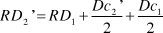
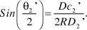
The intended number of unit cylinders N 2' within ring 2 can be calculated with reference to Equation 7. As N 2' is a non-integer, the value will be rounded to the closest whole number. Since the trabecular bone region is less dense than the cortical bone, N 2' is rounded up to generate ring 2 with lower porosity and obtain N 2, the actual or design value (whereas for cortical bone N2' will be rounded down). A reverse computational process is then applied using the actual N2 value and the aforementioned relevant equations. This iteration process will eventually compute the actual values of the physical parameters as defined in Equations 7 and 9, which give a complete second ring of N 2 cylinders. The overall diameter of the 3D FGS cylindrical system is then computed and stored.
For the inclusion of each concentric layer, repeated checks were carried out to verify if the overall diameter of the FGS has met the patient-specific requirements, as r is varied incrementally around an optimum value from the stiffness-porosity relationship for each region. Following the establishment of the structural features for the trabecular bone region, unit cylinders that exhibited comparable input stiffness to the cortical bone (according to the empirical stiffness-porosity relationship as discussed) were arranged around the trabecular regional structures. The algorithmic procedures for the cortical region were similar to that of the trabecular construct.
Verification of the radial FGS system
The feasibility of the automated radial FGS system for customized TE was assessed and verified by creating a femur segment using SLS. The first step of the verification process involved the generation of the 3D cylindrical FGS structure and the manipulation of data obtained via the CT scan of a patient’s femur segment. The inputs of essential parameters such as the stiffness, diameter, and thickness of the trabecular and cortical bone regions were required to obtain the desirable FGS model, while the data from the CT scan image were translated to the IGES file format using the MIMICS software. Second, the superimposition of the FGS structure and IGES graphical file was conducted to obtain a femur bone segment that incorporated a porosity or stiffness gradient. The overall process flow is illustrated in Figure 7. The resultant femur bone segment, which was incorporated with the FGS design, consisted of CAD data that were exported in the STL file format and processed via the selective laser-sintered application software (Build Setup version 3.3). Further working principles and the parameters used for the SLS fabrication process can be found in previous work.Reference Tan, Chua, Leong, Cheah, Gui, Tan and Wiria19, Reference Sudarmadji, Tan, Leong, Chua and Loh61, Reference Wiria, Leong, Chua and Liu64, Reference Wiria, Chua, Leong, Quah, Chandrasekaran and Lee65
A summarized flowchart of the patient-specific customization of the femur defect. FGS, functionally graded scaffold.

From current literature, the average diameters of the trabecular region and the cortical shaft of the femur were reported to be 2.30 cm and 3.14 cm, respectively.Reference Kaptoge, Dalzell, Folkerd, Doody, Khaw, Beck, Loveridge, Mawer, Berry, Shearer, Dowsett and Reeve66 The mean compressive stiffness of these two bone regions were evaluated to be 441 MPa and 17 GPa, respectively.Reference Cullinane, Einhorn, Bilezikian, Raisz and Rodan67 These stiffnesses were far greater than that of PCL scaffolds. As a result, the FGS system was unable to generate unit cylinders that meet the stiffness of the bone regions. Nevertheless, for the illustration of stiffness gradient within the radial FGS structure, the trabecular and cortical shafts were assigned 20 MPa and 65 MPa, respectively. The dimensional and mechanical property inputs were then entered and the radial FGS generated. The physical dimensions of the PCL scaffold were measured and were very close to the design values.
Discussion
In this study, an automated CAD system has been implemented to provide a more precise methodology for the customization of TE scaffold constructs. The radial FGS system aims to generate desirable geometrical features in FGS builds for the creation of an efficient environment for musculoskeletal tissue repair and regeneration. While there had been attempts to mimic such functional gradients with conventional TE scaffold fabrication methods, most of them achieved only variation in porosity and pore sizes (e.g., those that use different sizes of porogens or foaming methods by Werner,Reference Werner, Linner-Krcmar, Friess and Greil70 Vaz,Reference Vaz, Lopes and Almeida71 and TampieriReference Tampieri, Celotti, Sprio, Delcogliano and Franzese72 or the centrifuge method by OhReference Oh, Park, Kim and Lee73). Also, these methods have difficulties in maintaining control of the porosity and pore size gradient.Reference Leong, Chua, Sudarmadji and Yeong24 There are also methods that have taken advantage of AM technologies for better control of the porosity and pore size gradients (e.g., those that have been achieved with Theriform,Reference Sherwood, Riley, Palazzolo, Brown, Monkhouse, Coates, Griffith, Landeen and Ratcliffe43 FDM,Reference Kalita, Bose, Bandyopadhyay and Hosick37 and 3D fiber depositionReference Woodfield, Malda, de Wijn, Peters, Riesle and van Blitterswijk74, Reference Woodfield, van Blitterswijk, Riesle, de Wijn, Sims and Hollander75). Nevertheless the gradients that have been achieved are discrete in nature (i.e., a porosity gradient that is characterized by zones of fixed pore sizes with a disruptive interface between zones). The key advantage of the FGS system proposed here is that it has incorporated a radial stiffness gradient that mimics the anatomical structure of native bone. The variation in the stiffness and hence the porosity within each tissue construct served to more closely resemble that between the trabecular and cortical bone regions. The designed scaffold will thus provide a viable environment for the mass transportation of essential nutrients and the ability to withstand physiological loadings. With the CAD feature, Boolean operations could be performed to obtain a bone segment with an overall shape that was similar to that of the patient’s native bone. The resultant CAD bone segment file was then replicated into a physical model in conjunction with an existing AM technology.
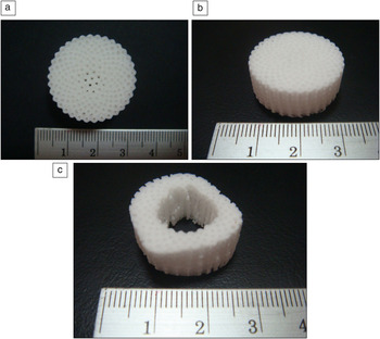
The present work used SLS for the fabrication of the physical FGS model. The entire process flow of the FGS model has been verified by the fabrication of the radial FGS, as shown in Figure 8. The radial FGS model complements the authors’ computer-aided system for tissue scaffolds (CASTS) system.Reference Naing, Chua, Leong and Wang23, Reference Cheah, Chua, Leong, Cheong and Naing25, Reference Chua, Leong, Cheah and Chua46, Reference Chua, Leong, Cheah and Chua50 The previous work done provided a valuable database for the assembly of different polyhedral units into a tissue construct to meet the required geometric properties, while the FGS system presented encompassed a novel concept to integrate the functional aspects. The radial FGS system, in comparison to the CASTS system, serves to mimic both physical and mechanical characteristics of the native bone by first assessing the stiffness-porosity relationships and subsequently incorporating the unit cells and algorithms for the scaffold assembly process. Nevertheless, the demonstration of the feasibility of the radial FGS system is motivated toward future work by the implementation of CASTS systems to include more options in the choice of unit cells (using different polyhedral units). The integration of both systems, together with the use of AM technology, is anticipated to enhance the existing solutions to CAD-based functional TE.
(a) Plan and (b) isometric views of the radial functionally graded scaffold (FGS) model built using selective laser sintering. (c) A femur segment incorporated with the radial FGS features is also fabricated. The numbered divisions are in cm.

The chosen material, PCL, for the AM manufacturing method has also been proven to be non-cytotoxic, which suggests that the tissue constructs exhibit negligible or minimal potential for toxicity. For AM fabrication, the current study encountered challenges that can be minimized or eliminated with minor changes. First, the compressive properties of the constructs are limited by the bulk characteristics of PCL. This limitation could be resolved by the expansion of material choice, using composites or through immobilizing the patient’s injured or damaged site using a cast until the fixation between the scaffold and the surrounding bone has been stabilized.Reference Sarmiento, Burkhalter and Latta68, Reference Mohtadi69 Next, the average particle size of the PCL powders was limited to 100 μm, which suggests that the surface topography of the scaffolds may not be appropriate as attachment sites for primary cells of different musculoskeletal tissues. To address this issue, other AM-based fabrication approaches may serve as alternatives to achieve the desired morphologies, since the FGS system is applicable to most direct and indirect AM methods. In addition, like existing CAD techniques for TE scaffolds, the radial FGS automated program may experience difficulties with fiber-based AM techniques such as the FDM and single-nozzle deposition technique, which will only enable the formation of a pore-sized gradient via laydown patterns.
Summary
This study has demonstrated a novel automated computer-aided design system that has been demonstrated as feasible for the customization of a patient-specific tissue engineering (TE) scaffold. The functionally graded scaffold (FGS) system developed showed the possibility of fabricating bone tissue constructs to meet the structural and mechanical requirements. In addition, the use of PCL as a biomaterial for the selective laser sintering manufacturing process fulfilled the biological requirements and thus was suitable for the production of the functional TE scaffolds for these experiments. The FGS may be explored for TE applications of other musculoskeletal tissues and integrated into the computer-aided system for tissue scaffolds system for more design options to the engineering of tissues and organs with challenging structural complexities.