I. INTRODUCTION
The left-handed materials offer exciting artificial dielectric and magnetic properties induced by electric and magnetic dipole moments. Incidence of time-varying fields on left-handed materials will yield negative permittivity and permeability [Reference Pendry1, Reference Boardman2]. Metamaterials (MTMs) are artificially created structures of finite size which have shown great potential to engineer the electromagnetic properties of the material [Reference Boardman2–Reference Alu and Engheta4].The split ring resonator (SRR) is a compact LC resonator, in which inductance L is formed due to metallic loops and capacitance C is formed due to dielectric gaps [Reference Pendry1]. SRRs have received immense attention in antenna design since its inception [Reference Fujimoto and Morshita3, Reference Alu and Engheta4].
The paper presents investigations on multilayer μ-negative stacked homogenous SRRs in conjunction with patch resonator. The patch antenna acts as primary radiating element, whereas dual layers of 3 × 3 SRR arrays are secondary radiating elements. The primary design novelty of the antenna is that antenna frequency tuning can be achieved by merely tailoring SRR dimensions. This would significantly help in freezing mechanical dimensions of surface mountable patch antenna for satellite L (1–2 GHz) and S (2–4 GHz) frequency bands applications.
SRR generates strong magnetic dipole moment for achieving negative permeability [Reference Palandoken5]:
 $$\mu _r \lpar \omega \rpar =1 - \displaystyle{{F\omega ^2 } \over {\omega ^2 - \omega _0^2 - j\omega \gamma _m }}\comma \; $$
where μ r is the frequency-dependent relative permeability, ω 0 is the resonance frequency, F is the unit-cell filling factor, and γ m is the damping coefficient. Since permeability follows the Lorentz model, SRR array would generate negative permeability when condition ω 0 < ω < ω pm is satisfied where ω pm is the magnetic resonance frequency. Negative refraction of split rings can be computed using numerous methods available in literature [Reference Palandoken5–Reference Chen, Grzegorczyk, Pacheco and Kong9]; however, methodology in [Reference Smith, Vier, Kroll and Schultz7] was employed to calculate the magnetic response of unit-cell SRR array using MATLAB.
The simulated scattering and impedance parameters are exerted in ABCD parameters as [Reference Palandoken5]
 $$A=\displaystyle{{Z_{11} } \over {Z_{21} }}\comma \; \quad B=\displaystyle{{Z_{11} Z_{22} - Z_{Z1}^2 } \over {Z_{21} }}\comma \; \quad C=\displaystyle{1 \over {Z_{21} }}\comma \; \quad D=\displaystyle{{Z_{22} } \over {Z_{21} }}\comma \;$$
where the complex propagation constant can be given as
 $$\gamma=\displaystyle{{\arccos \, h\left({\displaystyle{{A+D} \over 2}} \right)} \over {a_x }}.$$
The Bloch impedance can be defined as
 $$Z_B=\displaystyle{{Be^{ - \gamma d} } \over {1 - Ae^{ - \gamma d} }}.$$
The propagation constant is a complex quantity, which can be expressed in the form of attenuation constant and phase constant
 $$\gamma=\alpha+j\beta\comma \;$$
where α and β are attenuation and phase constants, respectively.
The effective relative permeability (μ reff)
 $$\mu _{reff}=\displaystyle{{ - j\gamma Z_B } \over {Z_{line} k_0 }}.$$
Based on impedance parameters extracted from the simulated SRR array unit cell, the computed effective relative permeability is illustrated in Fig. 1. In Fig. 1, the effect of exiting electric field resulting from the feeding potential difference between the patch and ground plane is taken into account instead of magnetic field. The effective relative permeability exhibits anti-resonance behavior, which is an expected result of neglection of bianisotropy in such kind of artificial structures in the referenced formulation in addition to the exciting electric field instead of the magnetic field.
Analytically computed relative permeability for SRR array.

The stacked SRR follows the phenomenon of electroinductive waves (EIWs) [Reference Beruete10]. The LH propagation can be achieved in stacked SRR regardless of coupling type [Reference Beruete10]. The presented design utilizes such configuration of subwavelength SRR arrays, which are coupled with the patch antenna. The periodicity of embedded structure is maintained. Stacking of substrate is carried out to increase gain and bandwidth of the antenna; however, due to high Q-factor of coupled resonating elements antenna bandwidth is restricted below 5% in presented design. The capacitive resonance is significant in stacked SRR arrays and it has significant importance on antenna resonance. In the proposed design, the yz-plane consists of symmetrical SRR arrays and hence they force symmetric magnetic field production. Effect of the presence of stacked SRR array is also presented in the Results section. The prototype is carefully fabricated; however, in case of any possible misalignment in SRR stacking antenna gain gets affected. Analysis of misalignment of SRR array stacking is demonstrated in the Results section.
Over the period of time, microstrip antenna size reduction is achieved by providing slots and lumped elements; however, using such techniques achieving other antenna parameters such as gain, bandwidth, and efficiency simultaneously for the application-specific design is very difficult [Reference Fujimoto and Morshita3]. Size reduction of the antenna with metallic inclusion in the substrate with combined use of planar thin wire and SRR was reported in [Reference Upadhyaya, Kosta, Dwivedi and Kosta11]. Analytical modeling of single-layer SRR-loaded patch antenna is thoroughly demonstrated in [Reference Billoti, Alu and Vegni12, Reference Yuandan, Toyao and Itoh13]. Such sub-wavelength metallic inclusions can be of any form such as electrically negative (ENG), magnetically negative (MNG), or double negative (DNG) materials. Negative refraction can also be achieved by asymmetric metallic cut wire pairs or non-isotropic structures [Reference Billoti, Alu and Vegni12, Reference Burokur and Lustrac14]. Negative refractive index inspired antennas have effectively shown increase in gain, bandwidth, and variable mode operation [Reference Alu, Billoti, Engheta and Vegni15]. The orientation of the metallic inclusions greatly affects the antenna polarization. Linear polarization, circular polarization, and elliptical polarization antennas can be achieved using negative refractive index materials [Reference Fujimoto and Morshita3].
Recent findings have attracted many microwave applications of negative refractive index materials. The negative refraction inspired antennas were proposed for electrically small antennas [Reference Palandoken5], multiple-input multiple-output (MIMO) communication antennas [Reference Ntaikos and Yioultsis16], broadband antennas [Reference Palandoken, Grede and Henke17], isotropic antennas [Reference Blaha, Machac and Rytir18], beam-tilting antennas [Reference Dadgarpour, Zarghooni, Virdee and Denidni19], ultra-wideband antennas [Reference Alhawari, Ismail and Mahdi20], high-gain satellite antennas [Reference Gheethan, Herzig and Mumcu21], adaptive antennas [Reference Jouvaud, Rosny and Ourir22], and implantable medical antennas [Reference Sanchez-Fernandez, Quevedo-Teruel, Requena-Carrion, Inclan-Sanchez and Rajo-Iglesias23].
The scaling of SRR is primary technique utilized for antenna tuning in the presented results; however, all SRR parameters presented in the antenna design section can be utilized for antenna tuning. The additional tuning flexibility in proposed design is provided by symmetric centerd slots. The impedance matching is done through transmission line. The proposed antenna was fabricated to validate the simulation results; both simulated and measured results present encouraging agreement. The effect of SRR scaling and inter-element spacing on corresponding antenna resonance and gain is also presented in results.
II. ANTENNA DESIGN
The proposed antenna geometry along with its design parameters is illustrated in Fig. 2. The symmetric center slotted rectangular patch antenna having area of 68.8 × 85.8 mm2 is on top of the layered structure and antenna is matched at 50 Ω with feed width f W and optimized length f L of 2.6 and 22.2 mm, respectively. The antenna consists of two stacked 3 × 3 SRR arrays sandwiched between dielectric substrates. The antenna is fabricated on Rogers RO-3003 having relative permittivity 3, loss tangent 0.0013, and thickness D Z of 1.54 mm, which is suitable for satellite antenna applications. Three substrate layers make the total antenna thickness of 4.62 mm.
Geometry of the proposed antenna.
The length G L and width G W of substrate is 94 and 110 mm, respectively. Ground plane dimensions are equal to the substrate dimensions. SRRs are uniformly distributed beneath patch antenna etched on both sides of substrate. SRRs are equally spaced at D X = D Y = 26.8 mm in the x–y plane. The feed connector is simulated with hole through in the substrates; however, to avoid drilling process, SMA connector is directly connected to transmission line in fabricated prototype. Screws at two corners of antenna are fixed for maintaining one on one alignment of stacked antenna sublayers. The dimensions of width f sw and length f sL for transmission line placement are 5.2 and 12 mm, respectively. The SRR dimensions in millimetre: L O = W O = 20, D O = 1, G O = 2, L i = W i = 16, D i = 1.5, and G i = 2.5.
An electrical equivalent circuit of dual μ-negative material-loaded patch antenna is illustrated in Fig. 2(d). The combination of R 1, C 1, and L 1 represents the antenna resistive and reactive components, C 2 and L 2 represents reactive components of the coupling elements. Antenna probe is considered as inductive lump element L p. L represents the inductance of SRR. R c and R d are conductive and dielectric resistance, respectively, due to metallic inclusion and antenna substrate. Capacitance C g is the gap capacitance for the gaps present in SRRs. Since the conducting inclusion is embedded between dielectric slabs of antenna, mutual capacitance C m and L m would also be present. The combined Q-factor of antenna and SRR would be in order of hundreds and which leads to extremely lower antenna bandwidth. Since SRR arrays are stacked in parallel to the conducting sheets, SRR arrays will form parallel resonator circuit.
The prototype of proposed antenna that was fabricated on RO 3003 substrate with ½ Oz copper coating is illustrated in Fig. 3. Figures 3(a) and 3(b) demonstrate the front and back views of antenna. Two such layers as shown in Fig. 3(c) are sandwiched between the patch and ground planes as illustrated in side of antenna in Fig. 3(d).
Fabricated prototype of the proposed antenna.
III. SIMULATED AND MEASURED RESULTS
Simulated and measured reflection coefficient (S 11) for the antenna is shown in Fig. 4. The antenna resonates at 1.17 and 3.212 GHz as per the requirement of GPS antenna. Voltage-standing wave ratio (VSWR) at L5 and S band are 1.34 and 1.20, respectively, both are meeting primary design criteria. Owing to high Q-factor of SRR array antenna 10-dB bandwidth is restricted abouts 2–3%, which is a fundamental drawback of the proposed design. Figure 5 illustrates the surface current of SRR structures embedded as sublayers of substrate in patch antenna.
Simulated and measured return loss (S 11).
Illustration of surface current of embedded SRR structures.
The simulated and measured radiation patterns on the H- (x–z) and E- (y–z) planes for 1.17 and 3.212 GHz are illustrated in Fig. 6. The H- and E-plane patterns exhibit dipole-kind patterns, which can be improved further by employing reflectors. The optimum measured antenna gain is 6.2 dBi at L5 band and 5.5 dBi at S band.
Measured antenna radiation patterns of the proposed antenna at f1 = 1.17 GHz (a) H-plane gain (b) E-plane gain; at f2 = 3.212 GHz (c) H-plane gain (d) E-plane gain.
Effect of alteration in SRR dimensions in reference to existing proposed design dimensions and cross-polarization levels are illustrated in Fig. 7. Figure 7(a) demonstrates the antenna resonance by reduction in size of SRRs. The size of SRR is scaled down in fraction due to which it is apparent that resonant frequency is getting increased in first band, however, second band frequency is decreased. The frequency increment in first band is ranged from 0.1 up to 0.5 GHz and frequency decrement in second band due to scaling down SRR is ranged from 0.5 up to 2 GHz. This frequency range is very wide without modifying external mechanical parameters of the antenna. The cross-polarization levels are well above the requirement for satellite communication antenna for entire frequency range.
Effect of SRR dimension variations on antenna resonance.
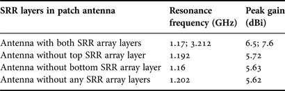
Effect of alteration in inter-element spacing in SRR arrays is illustrated against resonant frequency and cross-polarization in Fig. 7(b). The change in resonant frequency due to increase in inter-element spacing is quite less for both first and second resonance bands; however, noteworthy modification in cross-polarization is noted due to variation in gap between SRR array elements. These results can help to counter measure the reduction in the cross-polarization level occurred due to SRR scaling. The presence of SRR arrays in sublayers of patch antenna are vital in presented design. Analysis of antenna resonance and respective gain values in presence of SRR arrays are tabulated in Table 1.
SRR array loading effect analysis.
Table 1 demonstrates the analysis of SRR array loading in patch antenna. Gain enhancement is achieved in presence of dual stacked SRR array-loaded patch antenna. Absence of one of the layers of SRR array leaves only one resonance in targeted frequency regime. The antenna gain is also reduced by 0.78 dBi in the absence of top SRR array layer and 0.87 dBi in the absence of bottom SRR array layer. Noteworthy change occurs in absence of both SRR arrays. The frequency of resonance is increased and peak gain is reduced by 0.88 dBi.
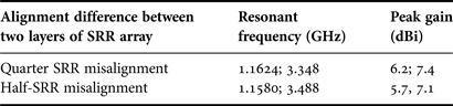
The proper alignment of SRR array in the multilayer structure of patch antenna is extremely important. In the case of misalignment of SRR array-loaded stacked substrate antenna, peak gain is reduced. Table 2 depicts values of resonant frequencies and peak gain for the misalignment of two SRR array layers. Resonant frequencies are significantly deviated from target frequencies and peak gain of antenna is also reduced.
Effect of SRR array.
IV. CONCLUSION
A novel design of dual-band, dual-stacked SRR array-loaded microstrip patch antenna is presented. The proposed antenna can be tuned for varied defense communication system applications operating in L and S bands by making appropriate variations in SRR array parameters. The vital benefit of proposed antenna is flexibility in antenna resonance tuning along with simultaneous achievement of required antenna gain and cross-polarization levels for satellite antennas. The design can be further improved by employing antenna bandwidth enhancement techniques.
ACKNOWLEDGEMENT
This work was sponsored by the Space Application Centre, Indian Space Research Organization, Department of Space, Government of India, under project grant number E-33011/58/2010-V.
 Trushit K. Upadhyaya received a B.E. in Electronics and Communication from Gujarat University, Gujarat, India in 2004 and received his M.E. degree in Telecommunication from University of South Australia, Adelaide, Australia. He is pursuing Ph.D. degree with specialization in Satellite Antenna Design. He also holds industry certifications. His main area of research is antenna design and applied electromagnetics. He has carried out several consultancy projects in area of antenna design for government and private agencies.
Shiv Prasad Kosta received his Ph.D. in 1970 from Jabalpur University. He was the Principal Engineer for India's first satellite “Aryabhatt”. He has got numerous awards and reorganization around the globe. He has served as Director of Indian Space Research Organization during 1981–1987. Since 2003 he is with Charotar University of Science and Technology as campus director. Government of India honored him with distinguished achievement award –1976, Robes of Honour – 1976, HRD Award – 1978, USSR Academic of Science Award –1977, and 12 other distinguished awards during the span of 1978–2006. He is published more than 130 research articles in international journals and conferences. He has published ten book chapters in Hindi. He has assisted satellite launch teams during 1975, 1977, and 1981 in USSR and France. He holds several prestigious fellowships in India and overseas. He has carried out several consultancy and R&D Projects for both government and private agencies.
Rajeev Jyoti received the M.S. degree in Physics and the M.Tech. degree in Microwave Electronics from Delhi University, Delhi, India, in 1984 and 1986, respectively. Since 1987, he has been involved in the Development of Antennas for Satellite Communication at the Space Applications Centre (SAC), Indian Space Research Organization (ISRO), Ahmedabad, India. Presently, he is the Group Director of the Antenna Systems Group at SAC, ISRO, India. He has more than 25 years of experience in the development of space borne and ground antennas at SAC. He has contributed significantly to the design, analysis, and development of microwave antennas, namely gridded antennas, multiple beam antennas, and phased array antennas for INSAT/GSAT, RISAT, and DMSAR projects. He has published more than 55 papers in various conferences and referred journals and he holds 14 patents. He was awarded the UN ESA Long Term Fellowship in Antenna and Propagation at ESTEC/ESA Noordwijk, The Netherlands.
Merih Palandöken received B.S. degree in Electrical and Electronics Engineering (with honors) from Cukurova University, Turkey, in 2002; M.S. degree in Microelectronics and Microsystems Engineering from Technical University of Hamburg, Germany, in 2005; and Ph.D. degree in Theoretical Electrical Engineering from Technical University of Berlin, Germany in 2012. He has been working in the analytical and numerical design and modeling of active/passive wireless components in the micro/millimeter wave frequencies especially in the field of metamaterial-based antennas and microwave filters.