

1 Introduction
With the growth of network, WiMAX is the new-generation telecommunication technology. It is based on IEEE 802.16 and provides access to metropolitan area networks (MANs). Because WiMax covers wider radio range, it can service more users than other networks. However, if there are too many users delivering data at the same time, the starvation in network capacity and radio interference might cause heavy degradation in network performance. To avoid the problems, in this paper, we propose a scheduling mechanism on the WiMAX Mesh mode. The proposed mechanism is built up on two-tier cluster-based routing tree. It not only avoids the interference but also maintains the efficiency of transmission. It also achieves both fairness and efficiency inside and outside the cluster. The simulation result shows that our mechanism provides great improvement in average delay time and throughput than other research.
The rest of the paper is organized as follows. In Section 2, some related works are discussed, and the proposed mechanism is introduced in Section 3. Section 4 provides analysis and discussion between our proposal and some related works. Section 5 concludes this paper.
2 Related works
When a user requests to send data, the network should decide the routing path for the transmission first. To find the proper route for the different source and destination pairs, some issues are considered and are necessary. In the WiMAX network, there are wider radio range and more users. If the radio interference is not counted in routing on the WiMAX network, the data communication might be disturbed or interrupted very often when there are many users in the network. Moreover, if the network capacity is not considered in routing, the transmission starvation might occur due to out of network bandwidth. Therefore, it is very important to find a route with no interference and enough network bandwidth.
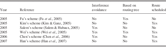
In the IEEE 802.16 medium access control layer, there are Mesh mode and PMP (Point-to-MultiPoint) mode (Sayenko et al., Reference Sayenko, Alanen and Hämäläinen2007), and the channel access are classified into single-channel accessing and multi-channel accessing schemes (Du et al., Reference Du, Jia, Huang and Lu2007). To provide better network performance and fair accessing in data transmission, the route scheduling is necessary. In previous research, because the communication cost is higher and covering nodes are limited in PMP mode, most routing strategies are based on Mesh mode. Moreover, the centralized scheme is easy to deploy and more efficient, most studies are built up on it. Among the route scheduling studies, there are centralized route scheduling schemes (Fu et al., Reference Fu, Cao and Fan2005; Kim & Ganz, Reference Kim and Ganz2005; Salem & Hubaux, Reference Salem and Hubaux2005; Wei et al., Reference Wei, Ganguly, Izmailov and Haas2005; Cao et al., Reference Cao, Raghunathan and Kumar2006; Chen et al., Reference Chen, Chi and Guo2006; Yang et al., Reference Yang, Liu and Yang2006; Han et al., Reference Han, Jia and Lin2007; Wang & Mutka, Reference Wang and Mutka2008; Wang et al., Reference Wang, Jia and Huang2008; Xergias et al., Reference Xergias, Passas and Salkintzis2008), and the distributed ones (Cao et al., Reference Cao, Ma and Wang2005; Chieh & Wang, Reference Chieh and Wang2007). In Table 1, the characteristics of some related works based on centralized routing strategies are listed.
The characteristics of some related works with centralized routing schemes
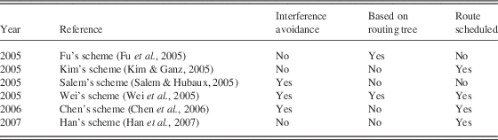
In Table 1, the Wei’s scheme (Wei et al., Reference Wei, Ganguly, Izmailov and Haas2005) provides all featuers: the scheme is built up on routing tree, and scheduling the route without interference. Han’s scheme (Han et al., Reference Han, Jia and Lin2007) proposed four scheduling schemes and found that the different sequence of nodes delivered would affect the transmission efficiency. In this paper, we propose a two-tier cluster-based route scheduling mechanism on Mesh mode. The proposal is a central routing algorithm with single-channel accessing. It not only avoids the interference but also maintains the efficiency of transmission. It also achieves both fairness and efficiency inside and outside the cluster. The proposed mechanism is introduced in the next section.
3 The cluster-based route scheduling algorithm for WiMAX network
In the proposal, we discuss the algorithms for two cases: the intra cluster and the extra cluster. The relationships between these two cases are depicted in Figure 1. In the coming sections, we will first introduce the routing tree creation for the intra cluster and extra cluster; then we explain the scheduling for the route in the intra cluster and extra cluster.
The relationships between the intra cluster and extra cluster in the proposal

Let T be the uplink frame allocated by BS (Base Station), and all nodes in the network are separated into several different clusters. There is only one clusterhead as the root node in each cluster tree, and the clusterhead mananges all transmittion in the cluster. Let C represents a cluster and nodes in the cluster are numbered as  $$n=\{ 1,2,3,\,\ldots\,,m\} $$
. Therefore, the nodes in the cluster i is represented by
 $$C_{n}^{i} =\{ C_{{\rm 1}}^{i} ,C_{{\rm 2}}^{i} ,C_{{\rm 3}}^{i} ,\,\ldots\,,C_{m}^{i} \} $$
. In this paper, because the proposal is based on IEEE 802.16d standard, every node in the cluster is fixed. The example topology for the proposal is shown in Figure 2, and the example topology with the single cluster and the cluster routing tree are given in Figure 3.
The network topology for the cluster-based structure
(a) The topology with single cluster. (b) The routing tree for the intra cluster
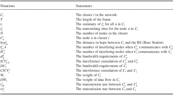
The symbols used in the proposal are defined in Table 2, and the time frame structure of the proposed mechanism is depicted in Figure 4.
Definition 1. If  $$C=\{ C_{n}^{i} ,t_{n}^{i} \} $$
is operable, if and only if there is at least one
 $$(C_{n}^{j} ,t_{n}^{j} )\,\subseteq\,C,{\rm 1}\les\ j\ \les\ n$$
existed with any
 $$t\in [{\rm 0},T]$$
.
Definition 2. If  $$U=\{ (C_{i} ,t_{i} )\} $$
is operable, if and only if there is at least one
 $$(C_{i} ,t_{i} )\,\subseteq\,U,{\rm 1}\les \ j \ \les\ n$$
existed with any
 $$t\in [0,T]$$
.
The time frame sructure for the poposed algorithm
Notations for the poposed algorithm
By the definitions, it is not able to operate if any of the following conditions is not satisfied:
 $$\left\{ {\matrix{ {\mathop{\sum}\nolimits_{i=1}^m {C_{i} \ \les \ T} } \cr {\mathop{\sum}\nolimits_{i=1}^n {C_{n}^{i} \ \les \ t} } \cr } } \right.$$
3.1 The routing tree creation algorithm for the intra-cluster case
This algorithm is based on Wei’s route construction algorithm for uplink (Wei et al., Reference Wei, Ganguly, Izmailov and Haas2005), and the routing tree is established with interference avoidance and bandwidth requirements. In the algorithm,  $$I_{{p,k}}^{i} $$
is the number of interfering nodes when node p communicates with node k, and
 $$dl_{p}^{i} $$
is the bandwidth requirements of node p. The algorithm is processed as follows:
1. The algorithm starts from the farthest node to the BS.
2. The number of interfering nodes for different route
 $$I_{{p,k}}^{i} $$
is computed.
3. The bandwidth requirements of interfering route
$$\mathop{\sum} dl_{p}^{i} $$
is calculated.4.
$$ICV_{{p,k}}^{i} =I_{{p,k}}^{i} {\times}\mathop{\sum} dl_{p}^{i} $$
5. The smallest
$$ICV_{{p,k}}^{i} $$
is selected for the route, and removing the node from the union.6. If there is a clusterhead near a hop, the clusterhead is added in the route.
7. Repeat the previous steps until all nodes are in the routing tree.


Let Figure 3(a) be the example network topology, the algorithm is run as below:
1. The farthest node to the clusterhead
$$C_{{\rm 9}}^{{\rm 1}} $$
is selected.2. According to the network topology, there is only one route for
$$C_{{\rm 6}}^{{\rm 1}} $$
and
$$C_{{\rm 9}}^{{\rm 1}} $$
.3. Then
$$C_{{\rm 8}}^{{\rm 1}} $$
is selected to route, and there are two routes,
$$C_{{\rm 5}}^{{\rm 1}} $$
and
$$C_{{\rm 6}}^{{\rm 1}} $$
, to select. The
$$I_{{p,k}}^{i} $$
are 5 and 4, and
$$\mathop{\sum} dl_{p}^{i} $$
is calculated to have
$$ICV_{{{\rm 5},{\rm 8}}}^{{\rm 1}} $$
as 58 and
$$ICV_{{{\rm 6},{\rm 8}}}^{{\rm 1}} $$
as 68. Therefore,
$$C_{{\rm 6}}^{{\rm 1}} $$
is selected.4. Repeat the previous steps to establish the complete route tree, as shown in Figure 3(b).


3.2 The routing tree creation algorithm for the extra-cluster case
This algorithm is similar to the one for the intra-cluster case. In the algorithm,  $$IC_{j}^{i} $$
is the number of interfering nodes when
 $$C_{i} $$
communicates with
 $$C_{j} $$
and
 $$dc_{j}^{i} $$
is the bandwidth requirement between
 $$C_{i} $$
and
 $$C_{j} $$
. The algorithm is processed as follows:
1. The algorithm starts from the farthest node to the clusterhead.
2. The number of interfering nodes for different routes
$$IC_{j}^{i} $$
is computed.3. The bandwidth requirements of interfering route
$$\mathop{\sum} dc_{j}^{i} $$
is summaried.4.
$$CICV_{j}^{i} =IC_{j}^{i} {\times}\mathop{\sum} dc_{j}^{i} $$
5. The smallest value of cluster is selected for the route.
6. Repeat the previous steps until all nodes are in the route tree.


Let Figure 2 be the example network topology, the algorithm is run as below:
1. The farthest node to the clusterhead
$$C_{{\rm 8}}^{{\rm 1}} $$
is selected.2. According to the network topology, there is only route one for
$$C_{{\rm 5}}^{{\rm 1}} $$
and
$$C_{{\rm 8}}^{{\rm 1}} $$
.3. Then
$$C_{{\rm 7}}^{{\rm 1}} $$
is selected. There are two routes
$$C_{{\rm 3}}^{{\rm 1}} $$
and
$$C_{{\rm 4}}^{{\rm 1}} $$
. The
$$IC_{j}^{i} $$
values are 3 and 4, and
$$\mathop{\sum} dc_{j}^{i} $$
is calculated to have
$$CICV_{{\rm 7}}^{{\rm 3}} $$
as 30 and
$$CICV_{{\rm 7}}^{{\rm 4}} $$
as 36. Therefore, the
$$C_{{\rm 3}}^{{\rm 1}} $$
is moved to the route.4. Repeat the previous steps until the complete routing tree is established, as shown in Figure 5.


The results of the routing tree creation for the extra-cluster case
Conbining the previous descriptions, Figure 6 lists the routing tree creation algorithm for the intra cluster and extra cluster. In the network, there are N nodes, and all nodes are processed in each round. Hence, the time complexity is O(N 2).
The routing tree creation algorithm for the intra cluster and extra cluster
3.3 The route scheduling algorithm for the intra-cluster case
This algorithm is modified from Han’s transmission-tree scheduling algorithm (Kim & Ganz, Reference Kim and Ganz2005). The algorithm starts from the nearest node to BS and schedules the route with bandwidth requirements. The process in the algorithm is described as follows:
1. The algorithm starts from the nearest node to BS.
2. The cluster with minimum bandwidth requirements is put into scheduling first.
3. According to the routing tree, the node without interference is added into the scheduling then.
4. Repeat the previous steps until all clusters are processed.
Let Figure 3(b) be the example topology, the algorithm is run as below:
1. The algorithm starts from the nearest node to the BS. There are
$$C_{{\rm 2}}^{{\rm 1}} $$
,
$$C_{{\rm 3}}^{{\rm 1}} $$
, and
$$C_{{\rm 4}}^{{\rm 1}} $$
in one hop range, and their bandwidth requirements are
$$dl_{{{\rm 1},{\rm 2}}}^{{\rm 1}} ={\rm 2}$$
,
$$dl_{{{\rm 1},{\rm 3}}}^{{\rm 1}} ={\rm 3}$$
, and
$$dl_{{{\rm 1},{\rm 4}}}^{{\rm 1}} ={\rm 5}$$
, respectively. Because
$$dl_{{{\rm 1},{\rm 2}}}^{{\rm 1}} $$
is the minimum among the tree values,
$$C_{{\rm 2}}^{{\rm 1}} $$
is put into the route scheduling process first.2. When
$$C_{{\rm 2}}^{{\rm 1}} $$
is delivering data, the interference nodes are
$$C_{{\rm 1}}^{{\rm 1}} $$
,
$$C_{{\rm 3}}^{{\rm 1}} $$
, and
$$C_{{\rm 5}}^{{\rm 1}} $$
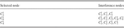
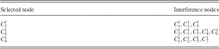
. In order to clearly represent the interference for each node, the interference table is created and shown in Table 3, and the intra-cluster route scheduling results is shown in Figure 7. According to the table, there are only
$$C_{{\rm 2}}^{{\rm 1}} $$
,
$$C_{{\rm 6}}^{{\rm 1}} $$
, and
$$C_{{\rm 4}}^{{\rm 1}} $$
nodes able to transmit data in time slot 1, without interference.


The results for the route scheduling algorithm executed in the intra cluster
The interference table for the transmitting in the intra cluster during the first time slot
The proposed route scheduling algorithm for intra cluster is described in Figure 8. There are N nodes, and the time slot for each node is t. Because there are at most n−1 interference nodes for each node, and the time complexity for the algorithm is O (N 2).
The route scheduling algorithm for the intra-cluster case
3.4 The route scheduling algorithm for the extra-cluster case
This algorithm is similar to the intra-cluster scheduling one. The clusters are assigned with weights that is the main difference between the two algorithms. The process in the algorithm is introduced as follows:
1. The algorithm starts from the nearest node to BS, and the weight for evey cluster is calculated as
$$DW_{i} =hop_{m}^{i} {\times}dc_{j}^{i} {\times}W_{i} $$
.2. The largest DW i is seleced first, and the links without interference are added in the route scheduling process.
3. According to the routing tree, the node without interference is added into the scheduling then.
4. Repeat the previous steps until all clusters are processed.

Let Figure 5 be the example topology, and the algorithm is run as follows. In the examples, let the weights of C 1−C 8 be 5, 3, 3, 6, 1, 4, 2, and 5, respectively.
1. The cluster C 1 and C 2 are in one hop range. Because their DW i are 10 and 18, C 2 is scheduled first. When C 2 is delivering data, the interference nodes are
$$C_{{\rm 1}} ,C_{{\rm 5}} $$
, and
$$C_{{\rm 6}} $$
.2. The interference table in transmitting is created in Table 4, and the results for the algorithm are shown in Figure 9.


The results for the route scheduling algorithm executed in the extra cluster
The interference table for the transmitting in the extra cluster during the first time slot

The proposed route scheduling algorithm for the extra cluster is described in Figure 10. There are N nodes, and the time slot for each node is t. Because there are at most  $$n{\minus}1$$
interference nodes for each node, the time complexity is
 $$O\(N^{{\rm 2}} )$$
.
The route scheduling algorithm for the extra-cluster case
4 Perforamnce analysis
In this section, the performance for the single cluster and multi cluster are simulated and analyzed. The simulations are run by NS-2, and nodes are randomly distributed in the range of 100×100 units. Every node in the network can send the data limited to five hops, and the transmission time for the intra-cluster case is 2 units, and the one between the clusters and BS is 8 units. In the single cluster, the simulations are examined with different number of nodes, 5, 10, 15, 20, and 25 nodes, in a cluster. In the multi cluster, there are five nodes in each cluster, and different number of clusters, two, four, and six clusters are assigned in the simulations. The following simulations compare the performance of proposed algorithm and the traditional IEEE 802.16d, and the results are showed in next sections.
4.1 The average delay time analysis for the single cluster
In this analysis, the average delay time is measured by seconds. When there are more nodes in the cluster, the network traffic will increase, and the average delay time will gradually increase too. In Figure 11, the simulation results show that our proposal does work and can provide lower average delay time than the traditional IEEE 802.16d.
The average dealy time for different nodes in the single cluster
4.2 The throughput analysis for the single cluster
In this analyais, the throughput is the packets received by a node in the unit time. When there are more nodes in the cluster, there will be more traffic in the limited network capacity, and the number of packets that every node can receive will be decreased. In Figure 12, the simulation results show that our proposal provides better route arrangement, and achieve better throughput than the traditional IEEE 802.16d.
The throughput for differenet nodes in the single cluster
4.3 The average delay time analysis for the multi cluster
When there are more clusters in the network, it is obvious that the network traffic will increase, and the average delay time will increase too. In Figure 13, the simulation results show that our proposal can still provide lower average delay time than the traditional IEEE 802.16d in the multi cluster network topology.
The average delay time for different clusters in the multi cluster
4.4 The throughput analysis for the multi cluster
When there are more clusters in the network, there will be more traffic in the limited network capacity, and the throughput of network will be decreased. In Figure 14, the simulation results show that our proposal provides better route arrangement, and achieve better throughput than the traditional IEEE 802.16d.
The throughput for different clusters in the multi cluster
According to the previous simulation results, our proposal did provide better performance than the traditional IEEE 802.16d. Comparing with the related works, our algorithm and Wei’s scheme (Wei et al., Reference Wei, Ganguly, Izmailov and Haas2005) are all developed with interference avoidance, route scheduling, and based on route tree. However, our proposal schedules the route with bandwidth requirements, but Wei’s scheme (Wei et al., Reference Wei, Ganguly, Izmailov and Haas2005) did not. Therefore, our algorithm provides not only more considerations in route scheduling but also better performance.
5 Conclusion
WiMAX is the new-generation telecommunication technology to provide access to MANs. As it covers wider radio range, it can service more users than other networks. To provide better network performance, in this paper, we propose a scheduling mechanism on the WiMAX Mesh mode. The proposed mechanism is built up on two-tier cluster-based routing tree. It not only avoids the interference but also maintains the efficiency of transmission. It also achieves both fairness and efficiency inside and outside the cluster. The simulation result shows that our mechanism provides great improvement in average delay time and throughput than other research.
In the future, in order to provide the pervasive networking, the proposal should be modified to be deployed on WiMAX PMP mode. Moreover, additional performance evaluations should be done to compare with other research or improve the mechanism.
Acknowledgements
This research was supported in part by the MKE (The Ministry of Knowledge Economy), Korea under the ITRC (Information Technology Research Center) support programme supervised by the NIPA (National IT Industry Promotion Agency; NIPA-2010-C1090-1031-0004), and the ROC NSC under contract numbers NSC97-2221-E-128-005-MY3.