I. INTRODUCTION
The novel technique termed inductively coupled power transfer (ICPT) is defined in this research as a system where power is transferred wirelessly across an air gap, by means of inductive coupling, from a static frame of reference to a stationary or movable load. Such systems are inherently based on magnetic field coupling. Such coupling can be either categorized as closely coupled k > 0.98 (virtually stationary load) or loosely coupled k < 0.05 (movable load), where k, is the coupling coefficient. Traditionally, conventional transformers and induction motors are examples of close magnetic coupling. Modern ICPT systems are generally described as loosely coupled with lengthy power transfer windows. Such systems are increasingly becoming ubiquitous in industry [Reference Jesus Sallan, Villa and Sanz1–Reference Barnard, Ferreira and van Wyk8]. This includes inherent advantages of the technique including no inconveniences caused from physical wires by providing power in hard to reach places, where conventional direct electrical connections are inconvenient, hazardous, or impossible [Reference Green and Boys9], lower maintenance requirements as there is less wear and tear from wet, dirty, moisturized and hazardous environments, provides enhanced safety as it is free of sparking so it can be used in potentially explosive atmosphere and freedom of mechanical movement. This has led to several industrial applications including monorail systems [Reference Elliott, Covic, Kacprzak and Boys10], mining [Reference Klontz, Divan, Novotny and Lorenz11], people-mover applications [Reference Wang, Stielau and Covic2, Reference Madawala and Thrimawithana4, Reference Sakamoto, Harada, Washimiya, Takehara, Matsuo and Nakao7, Reference Barnard, Ferreira and van Wyk8, Reference Covic, Elliott, Stielau, Green and Boys12], consumer battery charging [Reference Hui and Ho13, Reference Casanova, Low, Lin and Tseng14], and biomedical implantation [Reference Ping15]. A majority of current applications are based upon a confined source field distribution that largely only supports unidirectional and/or bidirectional load movements. That is, there is no support for free positioning three-dimensional (3D) load movements. This suggests the need for a source providing an omnidirectional cubic power transfer volume to support tri-directional load displacements. To date, 3D radiating omnidirectional inductive power surfaces has not been extensively researched. As the magnetic field arising from a coil immersed in a linear medium is unidirectional at any location, at least three distinct primary coils are required for the generation of three orthogonal magnetic field components. Notably, the magnetic field components are vector quantities with a single magnitude and direction in the space domain. Ideally, the receiver or pick-up axis must be aligned parallel to the magnetic field to maximize the mutual inductance and consequently power transfer. However, since the magnetic field decays as an inverse square law with distance, the curvature nature of the magnetic field poses many challenges for generating 3D omnidirectional primary track surfaces. Next, various existing techniques are reviewed in terms of 3D field generation and control and excitation. This paper will then present the proposed system structure. For this system, the primary and secondary magnetic structures are developed via finite-element-method (FEM) software. Next, the system is implemented and finally the system performance is evaluated.
A) Review of existing techniques
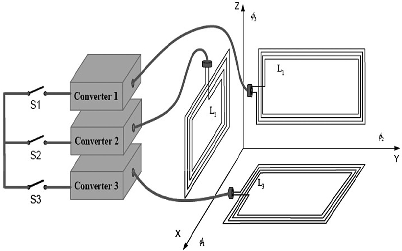
One approach to yield greater uniformity of magnetic field strength is to use rectangular Helmholtz coils [Reference OBrien, Teichmann and Gueldner16, Reference Schuder17]. The formation of the Helmholtz includes three sets of orthogonal rectangular coil pairs used to distribute magnetic flux along each of the three axes. Such an arrangement can ensure that a portion of generated flux is intercepted by a pick-up regardless of the pick-up orientation or position. This may be achieved by selectively switching on the particular Helmholtz pair that can achieve the highest magnetic coupling efficiency with the pick-up coils based on pick-up position and orientation (Fig. 1)
Helmholtz coil pair formation.

.
Another early proposal of such a 3D ICPT surface was in [Reference Schuder17] as illustrated in Figs 2 and 3. As illustrated, a rectangular coil is placed on each of the three orthogonal planes namely the YZ-coil producing B x, XZ-coil producing B y and the XY-coil producing B z. This concept was proposed for a 3D intended power zone of dimensions 2 m × 2 m × 2 m forming a cage-like structure around the coils as illustrated in Fig. 3. Evidently, the idea is to surround the pick-up with three primary coils along orthogonal axes. This arrangement can enable the simultaneous application of primary current in all three coils in order to generate a 3D radiating field. However, uniformity of magnetic field strength throughout the entire powering volume was poor. This was not only due to such a large power volume, but also because the coil arrangement produces valley regions near the outer edges and corners.
Schuders cage formation.
Schuders cage.
Another approach to generate a 3D power zone is to use an arrangement of three sets of orthogonal rectangular coil pairs used to distribute magnetic flux along each of the three axes [Reference Ping15] as shown in Fig. 4. Such an arrangement can ensure that a portion of generated flux is intercepted by a pick-up regardless of the pick-up orientation or position. This may be achieved by periodically switching on each Helmholtz pair on a timesharing basis such that each coil is excited for a third of the total time period. Using this technique, the total power transfer will also reduce to a third of the power transfer value attainable for the same value of coupling coefficient. In fact, [Reference Ping15] showed that the minimum flux through the pick-up will reduce to ϕ min/3, where ϕ min is the minimum value of the flux induced in the pickup due to each of the three primary Helmholtz coil pairs. Thus, the worst case open circuit voltage may be derived to produce equation (1).
 $$V_{oc} \geq \displaystyle{{\omega N_1 \varphi _{min} } \over 3}\comma \;$$
where V oc is the open circuit voltage, ω is the operating angular frequency and ϕ min is the minimum value of flux induced.
Multiple primary coils 3D formation.
Evidently, there exist various configurations of generating a 3D power transfer volume. Each configuration requires a form of control and excitation. Various techniques [Reference OBrien, Teichmann and Gueldner16] may be used for the excitation and control of the primary and secondary windings to achieve 3D power transfer. The most appropriate techniques for use with regards to an omnidirectional source are summarized below.
– Selective switching of pairs of primary coils based on the orientation of the pick-up axis [Reference OBrien, Teichmann and Gueldner16, Reference Schuder17]. With this technique, some knowledge of not only the pick-up position but also the power induced in the pick-up is required. This is to ensure the correct pair of primary coils can switch on while ensuring that the power induced in the pick-up does not drop below the threshold level required to operate a load.
– Using multiple primary layers with phase modulation between each layer [Reference OBrien, Teichmann and Gueldner16, Reference Mueller and Gyurcsik18]. In this way, the simultaneous excitation of each pair of coils can lead to a rotating (and travelling) field. So, by the development of a suitable current phase relationship the plane of field rotation may be controlled such that the field is distributed through all orientations.
– Controlling the magnitude of current in the primary coils [Reference OBrien, Teichmann and Gueldner16, Reference Lenaerts and Puers19]. With this technique, knowledge of the power induced in the pick-up to satisfactorily operate a load is required. This is often termed the threshold power. Based on this, the magnitude of primary current may be adjusted to maintain the threshold level of power induced in the pick-up.
– Combining a pick-up with multiple windings that are directionally distinct can potentially provide uniform power induction irrespective of pick-up orientation [Reference OBrien, Teichmann and Gueldner16, Reference Scheible, Schutz and Apneseth20]. The advantage of this technique is that it can be implemented with a bidirectional primary link.
– Adjusting the relative phases or the magnitude of the magnetic field vectors at a constant high frequency [Reference OBrien, Teichmann and Gueldner16, Reference Lenaerts and Puers21]. By doing so, the elliptical plane of rotation can be controlled to align with the pick-up axis for maximum power transfer. However, the caveat of this approach is that some knowledge of the plane of pick-up position and orientation is required.
– Inject current either locally in sets of coils or globally using pairs of multi-layer winding matrices to produce a direction of field travel that is in-phase so as to provide constructive interference and generate a radiating field distributed throughout a 3D volume [Reference OBrien, Teichmann and Gueldner16]. This field could be along one plane of rotation for a period of time and then in an orthogonal direction for another period of time.
– Start by switching on an arbitrary single primary coil at a time [Reference OBrien, Teichmann and Gueldner16]. Next, detect the amount of total power induced in the pick-up. If the required threshold power is not induced then switch another arbitrary primary coil on until. This process repeats itself until the required threshold power is induced. With this technique, the controller has no information regarding the pick-up position and orientation as the algorithm is based purely on whether the pick-up is receiving the sufficient required threshold power. This scheme can only work if an arbitrarily oriented pick-up can receive the threshold power from a single primary coil.
In previous approaches, the magnetic structures are not custom designed to distribute uniform magneto-motive force (MMF) over a 3D volume. This motivates the need to custom design magnetic structures by using a modern software JMAG Designer 10.0, utilizing the technique of the finite element method [Reference Elliott, Covic, Kacprzak and Boys10, Reference Tupsie, Isaramongkolrak and Paolaor22, Reference Kacprzak23] to produce a 3D operating power transfer volume.
II. PROPOSED ICPT SYSTEM
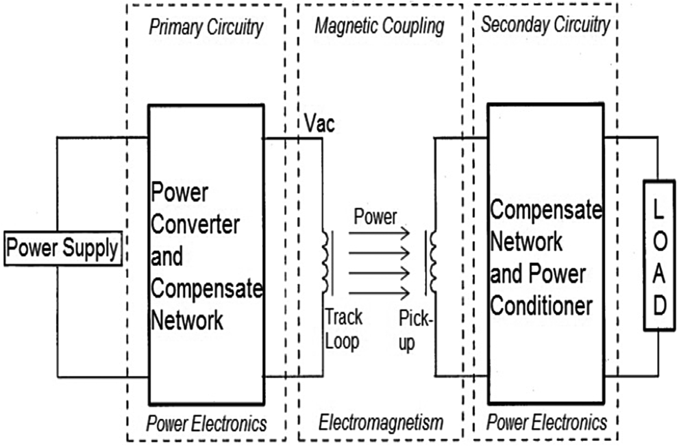
The operation of the ICPT system, illustrated in Fig. 5, may typically begin with a regulated (DC) voltage applied to the primary circuitry. The power converter inverts the input to produce a high-frequency AC current [Reference Madawala, Neath and Thrimawithana24, Reference Pinheiro, Jain and Joos25]. In this system, a push–pull topology as in [Reference Wu, Hu, Si, Budgett, Tang and Malpas26, Reference Hu, Covic and Boys27] is used to produce a sinusoidal current waveform of frequency 60 kHz. The following compensator networks provide resonance to maximize power transfer and efficiency [Reference Abe, Sakamoto and Harada28]. Next, the primary magnetic structure is used to distribute the AC current [Reference Lastowiecki and Staszewski29] to provide a 3D cubic power transfer volume. The next magnetic structure is related to the secondary circuitry, termed the pick-up, as custom designed to enhance power transfer capabilities [Reference Madawala, Neath and Thrimawithana24]. Owing to the loosely magnetic coupled nature of the pick-up, the induced voltage may be unsuitably low. As such, the induced voltage is resonated in the secondary circuitry by compensator networks [Reference Abe, Sakamoto and Harada28]. Following this, the AC voltage induced is then power conditioned to produce a regulated output voltage suitable to operate any load(s) [Reference Boys, Covic and Green30].
Proposed ICPT system structure.
III. PRIMARY MAGNETIC STRUCTURES
Two primary magnetic structures, with the purpose of providing a 3D power transfer window are proposed. The first primary magnetic structure proposed is excited with a single-phase current producing a net vertical field. The second primary magnetic structure proposed is excited with multiphase current producing a net horizontal field. Both structures are unique in the directionality of the field vectors and the input current phase. The FEM software JMAG Designer 10.0 was used for magnetic frequency analysis including triangular mesh elements of part size of 3 mm and air size of 5 mm, vectorial AC current at 60 kHz, symmetric boundary condition and FEM coils.
A) Vertical field box
In an effort to generate a 3D power transfer volume, it is proposed to use overlaid planar rectangular winding structures. Next, to improve the uniformity of the MMF distribution within the power zone it is proposed to encounter an increasing coil turn density toward the central region to compensate the central valley zone in the MMF as shown in Fig. 6. Each winding turn corresponds to dimensions of 5 × 10 mm. The resulting primary windings are surrounded by ferromagnetic material casing of relative permeability of 1200. This not only acts to enhance the field but also to provide a low reluctance pathway to the magnetic flux to confine the field within the ferrite reducing flux leakage and hence potentially harmful electromagnetic interference. The instantaneous magnetic flux density (MFD) distribution may further be visualized also in Fig. 6 through the central cross-sectional cut-plane of dimensions 130 × 90 mm by extracting each of the polynomial approximation values from the center of each element through the air region mesh to form the contour plot. This visualization displays the outer two peaks rapidly decaying to form valley regions. These valley regions are limited by the greater flux produced by the middle layers consisting of more ampere-current turns. This forms a peak in the center region. This improves overall field uniformity. The corresponding averaged MFD throughout the entire cubic power zone is 34.5 µT. The MFD variation with respect to this average is 131%. The next section considers reducing the ferromagnetic volume.
FEM model: primary winding (left), vertical field box (center), and magnetic flux density (right).
B) Vertical field box: stripes of ferrite
With ferrite being relatively heavier and more expensive compared to air it is desirable to reduce the total ferromagnetic volume of the system. To do this, it is proposed to use stripes of ferrite. This leads to two cases; vertical stripes of ferrite with ferrite volume 342 cm3 and horizontal stripes of ferrite with ferrite volume 432 cm3 as shown in Figs 3 and 4. The stripes include a ferrite-air material periodicity in the magnetic circuit that can act to attract and aid the flow of magnetic flux. The resulting MFD distribution across the central cross-sectional plane of the vertical field box with horizontal and vertical stripes of ferrite are also shown in Figs 7 and 8. The result with horizontal stripes of ferrite produces two peaks corresponding to the center of each horizontal stripe of ferrite. The central air gap within the ferrite casing accounts for a slight drop in the field forming a small valley zone. However, this is not significant as the surrounding peak zones help to improve overall uniformity of the flux distribution. This is in contrast to the case of vertical stripes of ferrite. Evidently, this case produces periodic outer peaks in phase with each vertical stripe of ferrite. The air gaps within the casing correspond to an outer valley zone. The central zone of the intended power zone appears as a valley region as the magnetic circuit consists of air gaps along the field propagation pathway.
Vertical field box with horizontal stripes of ferrite: FEM model (left) and magnetic flux density distribution (right).
Vertical field box with vertical stripes of ferrite: FEM model (left) and magnetic flux density distribution (right).
The resulting averaged magnitude MFD |B| within the total cubic powering volume shows that the orientation of horizontal stripes of ferrite provides a reduction in |B| by 3.16% compared to a full ferromagnetic casing. This may be explained by the composition of the averaged normal MFD B n. As this accounts for 88.7% of the net magnitude flux, horizontal stripes of ferrite result in the incidence of the magnetic flux vectors almost directly perpendicular to the ferrite-air transition boundaries. This is harmful for flux propagation through boundaries with such differing relative permeability's composing the ferromagnetic circuit. This is in contrast to the orientation of vertical ferrite stripes. In this case, the |B| has improved by 1.47%. This results in the predominant component of B n of 94% being traversed through the ferrite in directly parallel to the ferrite and air gaps. Such propagation is beneficial for the flow of flux and the lower volume of ferrite casing does not attract flux outwards but rather the field is able to be dispersed into the intended power zone. Overall, the modification to the magnetic circuit with vertical stripes of ferrite has proved beneficial towards improving |B| within the cubic power zone.
C) Horizontal field box
The aim of the multiple-phase AC current excitation structure is to distribute a time-varying and non-zero magnetic flux throughout the whole period of the input current cycle in order to generate 3D power transfer window. The proposed excitation current technique is to apply two independent currents, I 1(t) and I 2(t) that are of equal magnitude but in phase-quadrature. This means one current encounters an initial 90° phase delay. The proposed multi-phase currents are shown in Fig. 9. The resulting net current magnitude current I(t) is shown as being the sum of I 1(t) and I 2(t). The absolute current values arise as the magnitude MFD to be examined is proportional to this. The resulting modulated I(t) is evidently positive, encounters no zero-crossings and periodic with a constant maximum value while the minima are periodic with the envelope tracing another sinusoidal wave. Such a net wave of current implies that the pick-up may align with the resulting field in all orientations for all instants in time. The net resulting ICPT system may then be termed as generating a truly omnidirectional primary link. The arrangement of the primary winding structures are to be such that they form a 3D power transfer volume and also enable the application of phase-quadrature currents for continuous operation. For such a requirement, it is considered to use Helmholtz coil pairs. The advantage of the Helmholtz coil pair is that it creates more uniform field strength along the pair's axis that can lead to a 3D powering volume.
Horizontal field box: conceptual design.
In an effort to lower the unintended radiation in the outer top and bottom-most regions, a horizontal field concept is proposed. In this concept, the horizontally oriented planar components of the MFD B x, and B y that lie within a horizontal plane is intuitively made predominant in this concept. This means this multi-phase current system model is based on the predominant tangential components. This is done by orienting four rectangular windings faced opposite and adjacent to each other to form a 3D power emission volume as shown in Fig. 9. This configuration is unique in that by utilizing two planar components enables the sequential and phase quadrature application of the input primary currents. That is, the current magnitude of the current in each of the four rectangular windings is the same |I 1| = |I 2| = |I 3| = |I 4| but the current polarity of each winding opposes the directly opposite spiral such that I 1(t) = I 2(t) and I 1(t − 90°) = I 2(t − 90°). Notably, the currents in two of the adjacently placed coils encounter a current in-phase quadrature with respect to the other two coils. This produces B x(t), while two of these spirals along the same plane produce a magnetic flux that is 90°out of phase producing B y(t − 90°). This essentially produces a rotating magnetic field tracing an elliptical pathway.
The resulting multi-phase horizontal field box is shown in Fig. 10. Instantaneously, only one pair of coil is switched on by the proposed current cycle. As such, in the simulation of the magnetic frequency analysis the instantaneous zero-phase angle will only reflect the case of one coil pair being switched on whereas the other coil pair is switched off. The magnetic frequency analysis presented here performed when two coils are fully switched on to reflect the scenario that occurs every cycle. Initially, this is somewhat justified as the averaged MFD throughout the cubic volume with both coil pairs fully switched on is 22.7 µT as opposed to the case of one coil pair switched on is 17.4 µT. Hence, the increase in MFD with the second coil pair switched on is not doubly beneficial due to destructive interference by adjacent like poles. The resulting MFD contour distribution is also shown in Fig. 10. The field is relatively uniform between horizontal distances of 70–130 mm with a variation of 18.15%. However, the magnitude of the field strength is clearly weaker than the single-phase system. Note, the results presented here are based upon the magnetic frequency response to represent the instantaneous response of the system.
FEM model: primary winding (left), horizontal field box (center), and magnetic flux density (right).
C) Horizontal field box: stripes of ferrite
In an effort to tailor a more uniform MMF distribution and also reduce the total ferromagnetic volume required by the system, it has been proposed to consider stripes of ferrite. The stripes of ferrite include an air to ferrite material periodicity. Two orientations of ferrite stripes are considered, horizontal stripes of ferrite volume V = 432 cm3 as shown in Fig. 11 and vertical stripes of V = 324 cm3 as shown in Fig. 8. The resulting MFD distribution across the central cross-sectional plane of the horizontal field box with horizontal and vertical stripes of ferrite are also shown in Figs 11 and 12. The case of horizontal stripes of ferrite consists of two strong impulses in the magnetic flux corresponding to the top and bottom ferrite stripe zones. The central region consists of a rapid decay in flux forming a valley zone coincident with the central air gap. This is in contrast with the case of vertical stripes of ferrite. Evidently, this case produces periodic valley zones with the largest valley zone coincident with the ferrite stripe closest to the center of the intended power zone. As a result, the central valley zone is not significantly shallower as the peak is not a significantly more impulsive. As the outer smaller valley zones contribute to the result of an overall more uniform field distribution.
Horizontal field box with horizontal stripes of ferrite: FEM model (left) and magnetic flux density distribution (right).
Horizontal field box with vertical stripes of ferrite: FEM model (left) and magnetic flux density distribution (right).
Over the entire cubic powering volume, when compared with the case of a full ferromagnetic material casing, the result shows that the case of horizontal stripes of ferrite provides an improvement in |B| by 4.6% and the case of vertical stripes of ferrite provides a reduction in |B| by 28.74%. Both cases provide improvements in |B| by factors of 1.93 and 1.31 compared to an air casing. Clearly, the case of horizontal stripes of ferrite is most beneficial. As it was shown earlier that the propagating field is predominantly tangential, this may be explained by B t. Using horizontal stripes of ferrite the proportion of B t in |B| is 87.36%. This is higher than the same ratio achieved by vertical stripes of ferrite by just 0.26%. However, horizontal stripes is producing a |B| that is significantly higher as the horizontally travelling flux vectors prefer the magnetic circuit oriented parallel to the flux flow path rather than perpendicular. This results in greater enhancement and attraction of the component of flux parallel to the magnetic material than the smaller component that is perpendicular or vertical. Therefore, using horizontal stripes of ferrite an improvement in |B| may be achieved while also reducing the amount of ferrite required in the system.
IV. SECONDARY MAGNETIC STRUCTURE
The pick-up core is to be developed around the shape of an AA battery cell for industrial consumer battery charging. This lays the fundamental building foundation of core to be of a cylindrical cross-sectional shape. The idea is to use the developed core to support the insertion of the battery cell within the pick-up. That is, the pick-up core is to accommodate the battery cell for efficient use of space and steering of the flux vectors. This leads to a hollow cylindrical section of the core extruded to support the length of the battery. The result is a vertical oriented ferromagnetic hollow cylindrical core. Such a vertical section of the magnetic circuit supports the vertical B z component of magnetic flux density. In an effort to develop a tri-directional pick-up core, to also support the planar B x and B y component of magnetic flux, it is considered to add further ferrite blocks to the outer surface of the current core. This includes two rectangular blocks of ferrite along the x-axis. This will support the B x planar component of flux. Next, another two rectangular blocks of ferrite are placed along the orthogonal y-axis. This will support the B y planar component of magnetic flux. The resulting ferromagnetic pick-up core is shown in Fig. 13.
Pick-up: ferrite core view with conductive pathway of magnetic flux.
Next, the coil winding orientation is of interest. The short circuit pick-up coil current is proportional to the cross-section of solid coil perpendicular to the flow of current. Furthermore, the open circuit pick-up coil voltage is proportional to the cross-section of the magnetic structure that is perpendicular to the vectors of the magnetic flux density. So, the pick-up must be designed to specifically taking account of these conditions to maximize the induced uncompensated power. Furthermore, the higher the number of secondary power coils in the design the more secondary circuitry is required increasing component cost, size and power dissipation. In order to ensure develop a tri-directional (x, y, z) pick-up, it is proposed to use three pickup power coils. The planar coils x and y are to be wound along the parallel rectangular blocks of ferrite along orthogonal axes as shown in Fig. 14. Finally, the vertical coil z is to be found cylindrically around the outer of the resulting pick-up. This leads to the tri-directional pick-up shown in Fig. 14. This requires a total of three series pick-up coils to account for the planar and normal components of flux induction. The battery may be accommodated within the air gap of the inner core. As this pick-up is designed to induce flux from three orthogonal axes, it is expected that the pick-up can receive power irrespective of pick-up position and orientation. The next section aims to evaluate the pick-up performance.
Proposed tri-directional pick-up.
A) Pick-up performance: uncompensated power
For the purposes of pick-up performance evaluation via FEM simulation, the magnitude of the uncompensated power in each coil is summed as pick-ups in series. Notably, the uncompensated power S u is defined as the product between the open circuit voltage V oc and short circuit current I sc as in equation (2)
 $$S_u=V_{oc} \times I_{sc}.$$
This is essentially the power level induced in the secondary pick-up coil before the resonant or compensation stage. Typically, the uncompensated power may be improved by a factor of the quality Q of the compensation network. Firstly, the vertical orientation of the pick-up is tested through the center plane with the pick-up translated in 10 mm steps in both the vertical and horizontal field boxes as shown in Fig. 15. The result shows an average total uncompensated power level of 1.4 W and 650 mW with a deviation of 101.3% for the vertical field box and 150.08% for the horizontal field box. Secondly, the pick-up is rotated 90° for considering the horizontal orientation of the pick-up. Similarly, the pick-up performance is evaluated through the center plane with the pick-up being translated in 10 mm steps in both the vertical and horizontal field boxes also shown in Fig. 11. The result shows an average total uncompensated power level of 1.07 W and 458 mW with deviation of 171.14% for the vertical field box and 188.25% for the horizontal field box. Overall, the results show that the summation of the total uncompensated power induced in all three secondary pickup power coils is satisfactory for low-power consumer battery charging applications while the relatively high-power variation, compared to traditional ICPT applications, is explained by the fact that the aspect ratios of the power transfer volume are to support 3D producing a very loosely coupled power transfer system. One concerning aspect of this pick-up design may be attributable to thermal effects induced within the battery. This is considered in the next section.
Simulated uncompensated power level.
B) Pick-up load: thermal effects
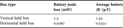
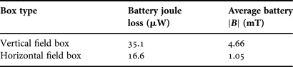
The main issue for consideration in the pick-up design, particularly related to the load placement of the AA battery cell within a battery cavity accommodated in the inner part of the ferromagnetic core is that of thermal effects. This is not only due to the non-zero temperature coefficient of initial relative permeability of the ferromagnetic material, but also because of the metallic material of the battery cell leading to potentially induced currents and hence a magneto-thermodynamic phenomenon. The magneto-thermodynamic phenomenon or adiabatic demagnetization refers to the change in temperature of a material as caused by exposing the material to a changing magnetic field. In this system, this can be understood as the changing strength of the primary magnetic field intercepted by the pick-up core, coils and the load allows the magnetic domains of the core material to become disoriented from the magnetic field by agitating action of the thermal energy in form of phonons within the material. This effect is undesirable as it increases the load or battery cell temperature cavity where the cell is located, it is proposed to add an aluminum foil on the inner part of the hollow cylindrical ferromagnetic core to isolate the battery cavity from the full effects this phenomenon as shown in Fig. 16. In order to quantify the effects two parameters are of particular interest. Firstly, the joule loss within the battery cell material. This will provide information in terms of the power or energy that is absorbed within the copper cell. This in turn is proportional to the thermal heat within the battery cavity. In order to enable the FEM simulation of this parameter, the effect of eddy currents within the copper cell material is enabled. The parameter of joule loss, with the aluminum foil included, will be considered in the aluminum foil itself so as to indicate how effective the foil is in absorbing energy to provide shielding of thermal heat to the battery cell. Secondly, the averaged magnitude MFD B within the battery cavity is also considered as the temperature change is proportional to this parameter. This parameter is also extracted for both cases including with and without the aluminum foil.
Pick-up core: with aluminum foil.
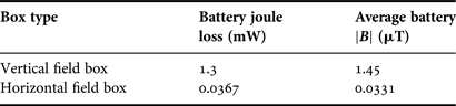
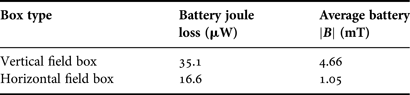
The resulting pick-up core thermal effects without the aluminum foil is tabulated in Table 1. The result shows that the vertical field box has a high joule loss within the batter cell compared to the horizontal field box by a factor of 35.42. This is due to the vertical oriented cylindrical cross-section of the core inducing the vertical field from the single-phase system producing a greater averaged B within the battery cavity by a factor of 43.81. In comparison, the case of the pick-up core thermal effects with the aluminum foil is tabulated in Table 2. The result shows that the joule loss within the battery cell for the vertical field box is now greater by a factor of 2.11 compared to the horizontal field box. By adding the aluminum foil the joule loss or energy absorbed by the battery cell has been reduced by a factor of 37.04 for the vertical field box and 2.21 for the vertical field box. This is a great improvement and suggests the battery cell temperature is reduced by adding the aluminum foil. This is largely due to the absorption of energy provided by the aluminum foil. This absorption measured in joule loss for the vertical and horizontal field boxes is 4.66 and 1.05 mW. By including the aluminum foil, the averaged B within the cell is also reduced in the vertical and horizontal field boxes by factors of 17.92 and 6.38 compared to without the aluminum foil. Hence, the thermal effects within the battery cell cavity may be reduced within the cell by use of an aluminum foil as a shield.
Pick-up core: without aluminum foil.
Pick-up core: with aluminum foil.
V. SYSTEM IMPLEMENTATION AND EXPERIMENTATION
For system implementation and experimental verification, the proposed model with the highest performance in terms of the average strength of magnitude MFD generated within the intended power zone is chosen. This is the vertical field box that is excited with a single-phase power converter. The type of inverter used is shown in the following section. Next, the implemented primary and secondary magnetic structures of the system are presented. Finally, experimental distribution of the induced RMS open circuit voltage and short circuit current are presented to calculate an uncompensated power level. The implemented system compared overcomes the limitations in past approaches such as the need for multiple power converters, multi-phase power switching circuitry, very low-power levels, lack of uniformity in magneto-motive force and lack of custom design by a tailored winding structure with single-phase excitation to improve the magneto-motive force strength and uniformity and as well as a custom secondary core to provide a low-reluctance magnetic circuit to improve voltage induction in the secondary circuitry.
A) Power converter
The type of power converter used to test the proposed system is a push–pull autonomous and zero-voltage-switching (ZVS) capable inverter for DC–AC conversion. This inverter does not require external controllers hence reduces switch controller and inverter switching losses. The circuit schematic is shown in Fig. 17. The resulting switching waveform with low distortion displaying ZVS and the resulting primary track current is shown in Fig. 18.
Power converter: circuit schematic (left) and PCB implementation (right).
Power converter: switching waveform (left) and track current (right).
B) Primary magnetic structure
The primary magnetic casing structure was implemented out of blocks of ferromagnetic material. This includes ferrite-glue or air transitions within the casing. This may reduce the overall relative permeability of the core. However, this is inevitable for a custom developed core of specific dimensions. Furthermore, in contrast to the idealistic materials used for simulation in practice the ferromagnetic material will induce eddy currents as well as encounter hysteresis loss. In order to reduce losses from high-frequency effects in the primary windings, Litz wire capable of AC current at 60 kHz are used. The resulting structure is shown in Fig. 19.
Primary magnetic structure: vertical field box.
C) Secondary magnetic structure
The proposed pick-up core is a unique and custom shape with specific dimensions tailored around an AA battery load. Similar to the primary structure, four toroid blocks of ferrite were used to form the hollow cylindrical core. This section of the core induces the normal component of magnetic flux. Next, two pairs rectangular blocks were used to form the flux flow path for each of the planar components of magnetic flux. The resulting core is wound with Litz wire for inducing high-frequency AC current. The resulting ferromagnetic pick-up core and windings with an AA battery load are shown in Fig. 20.
Secondary magnetic structure: ferromagnetic core (left) and pick-up windings (right).
D) Experimental results
The RMS open circuit voltage and short circuit current in each coil x, y, and z is measured using Agilent technologies voltage and current probe N2783A on the bottom plane (150 × 90 mm) of the intended power zone 5 mm steps as shown in Figs 21 and 22.
Induced RMS open circuit voltage in coil x, y, and z.
Induced short circuit current in coil x, y, and z.
The resulting product between the RMS open circuit voltage and short circuit in each coil and corresponding series summation of the total uncompensated power is shown in Fig. 23. The result shows an average power level of 2.67 W with a variation of 29.5% from the average power level.
Total series summation of the uncompensated power in each coil x, y, and z.
VI. CONCLUSION
This paper has proposed the custom development of the primary and secondary magnetic structures composing a 3D inductively coupled power transfer system. This was done via finite element analysis software to produce a suitable MFD distribution over a 3D volume. The resulting design chosen for implementation has an averaged MFD of 34.5 µT throughout the intended power zone. Upon implementation of the system, the resulting averaged uncompensated power level is measured to be 2.67 W with a standard deviation of 29.5%. In comparison to past approaches, this paper has developed a low reluctance magnetic circuit via customized primary and secondary magnetic structures using modern software techniques for low-power induction to overcome past limitations such as the need for multiple power converters, multi-phase power switching circuitry, very low-power levels, lack of uniformity in magneto-motive force and lack of custom design. The proposed system is suitable for consumer battery cell charging or low-power electronics applications.
Pratik Raval received his Master's degree with first class honors in Electrical and Computer Engineering from The University of Auckland in 2010. Since 2011, he has been doing his Ph.D. in the research area of inductively coupled power transfer, electromagnetism and magnetics. The research consists of generating a three-dimensional wireless power transfer source for three-dimensional free positioning applications with effective electromagnetic shielding producing a low flux leakage.
Dariusz Kacprzak graduated from the Lublin Technical University (Poland) in 1996. He obtained his Ph.D. from Kanazawa University (Japan) in 2001 in the field of eddy current testing for PCB defects. From 2001 to 2003, he was a Lecturer at The University of Auckland, New Zealand. Now, he is a Senior Lecturer at the same university. His is interested in magnetic modeling, nondestructive testing, and novel applications of electromagnetism.
Aiguo P. Hu graduated from Xian JiaoTong University, China, with BE and ME degrees in 1985 and 1988, respectively. He received his Ph.D. from the University of Auckland in 2001 before he worked as a lecturer, director of China Italy Cooperative Technical Training Center in Xian, and the general manager of a technical development company. Funded by Asian2000, he stayed in NUS (National University of Singapore) for half a year as an exchange research fellow. He holds eight patents in wireless/contactless power transfer and microcomputer control technology, published more than 130 referred journal and conference papers, authored the first monograph on wireless inductive power transfer technology, and contributed four book chapters on inductive power transfer modeling/control and electrical machines.
Patrick is currently the Director of Graduate Studies in the Department of Electrical and Electronic Engineering, the University of Auckland, New Zealand, and also a guest professor of ChongQing University. He is a Senior Member of IEEE, the former Chairman of IEEE Power Systems/Power Electronics Chapter, and the current Secretary/Treasurer of NZ North Section. He also served as Secretary/Treasurer of NZ Chinese Scientists Association and now sits on the organizing committee. His research interests include wireless/contactless power transfer technologies and application of power electronics in renewable energy systems.