NOMENCLATURE
Greek Symbol
- c
-
chord
- Cd
-
section drag coefficient
- Cl
-
section lift coefficient
- Cm
-
section moment coefficient
- Cp
-
section pressure coefficient
- R
-
rotor radius
Acronym
- AoA
-
angle-of-attack
- ATE
-
active trailing edge
- ATR
-
active twist rotor
- CFD
-
computational fluid dynamics
- CSD
-
computational structure dynamics
- CTEF
-
continuous trailing-edge flap
- DTEF
-
discrete trailing-edge flap
- FSI
-
fluid structure interaction
- MFC
-
macro-fibre composite
- TEF
-
trailing-edge flap
1.0 INTRODUCTION
This paper presents the design and optimisation of an aerofoil with active Continuous Trailing-Edge Flap (CTEF). The CTEF design uses embedded active materials inside the aerofoil section to distort the trailing-edge section dynamically(Reference Maucher, Grohmann, Janker, Altmikus, Jensen and Baier1-Reference Shen, Thornburgh, Kreshock, Wilbur and Liu3). Its potential applications are similar to the widely studied Discrete Trailing-Edge Flap (DTEF)(Reference Shen, Yang and Chopra4) and Active Twist Rotor (ATR)(Reference Fogarty, Wilbur and Sekula5,Reference Thornburgh, Kreshock and Wilbur6) , including active control of helicopter rotor vibration and noise, performance improvements and in-flight rotor blade tracking. In addition, the CTEF is being investigated as the potential device for swashplateless rotor control(Reference Sekula and Wilbur7), which requires relatively high control authority.
Like the majority of the active control systems proposed, Trailing-Edge Flaps (TEFs) target the major source of the helicopter vibration and noise, the main rotor and propose to alter its aerodynamic and dynamic behavior adaptively to achieve the control goal. A TEF only takes a small portion of the rotor span, but it can effectively modify the rotor response by changing the rotor pitch angle elastically. A common TEF design is the discrete flap, which typically consists of an active driving mechanism and various hinges and levers to convert and amplify the piezoelectric strain into a TEF deflection. The major challenge of such design is the high centrifugal loading found in a rotor, which is particularly challenging to DTEF systems. The brittle piezoelectric stacks tend to break, and the effectiveness of the lever amplification mechanism is reduced. An alternative to DTEF design is the ATR(Reference Thornburgh, Kreshock and Wilbur6). Its capability in reducing vibration and noise has been shown in several wind tunnel experiments(Reference Wilbur, Mirick, William, Yeager, Langston, Cesnik and Shin8). Active piezoelectric layers are built into the blade sectional layout, and the elastic twist is dynamically altered along the blade when the layers are activated. An attractive aspect of ATR lies in the unique feature of the Macro-Fibre Composite (MFC) actuators: active piezoceramic fibres are embedded in a polymeric matrix(Reference Wilkie, Bryant, High, Fox, Hellbaum, Anthony Jalink, Little and Mirick9). The matrix protects the fibres and also allows the actuators to be applied to a curved surface, such as aerofoil skins. A drawback of the ATR concept is that the actuators have to be applied along a major portion of the blade to be effective. A modified DTEF design, Active Trailing-Edge (ATE) concept, was proposed recently(Reference Maucher, Grohmann, Janker, Altmikus, Jensen and Baier1,Reference Grohmann, Muller, Achci, Pfaller, Bauer, Maucher, Dieterich, Storm and Janker2) . In order to eliminate the aforementioned hinges and levers mechanism typically found in a DTEF, the aerofoil trailing edge, which is soft in design, is deformed with a piezoceramic stack bimorph. The piezoceramic stacks used in the ATE concept, however, are still exposed to the high stress condition found in a rotor blade. In order to protect the piezo-stacks from breaking under adverse tension loads, the bimorph has to be cut into small patches along the span-wise direction(Reference Grohmann, Muller, Achci, Pfaller, Bauer, Maucher, Dieterich, Storm and Janker2).
An active CTEF concept, implemented with embedded MFC bimorph bender, was proposed by the authors(Reference Shen, Thornburgh, Kreshock, Wilbur and Liu3). It was considered to combine the advantages of the ATR and ATE concepts: eliminating moving parts typically found in a discrete trailing-edge flap, such as hinges and levers, and avoiding the complex arrangement of protecting piezoceramic stacks with partitioning. This simplification in structural design potentially leads to a reduction in rotor weight and maintenance requirements. Reference 3 presented the preliminary CTEF design and developed structural cross-section models of NASTRAN and UM/VABS and 2D aerodynamic models of OVERTURNS Computational Fluid Dynamics (CFD) analysis to evaluate the CTEF aerofoil. The aerodynamic efficiency of a CTEF was compared to that of a conventional DTEF. The CTEF design was only preliminary and not optimised because of the drawback of the NASTRAN and UM/VABS cross-sectional models used. Besides the relative computational intensiveness of these analyses, it is challenging to develop a tool that is capable of automatically meshing the cross-section for new design iterations. This makes them difficult to use in an optimisation framework.
This paper presents the development of reduced-order static aeroelastic models of a CTEF, which is needed in conducting effective optimisation of the CTEF designs. High-fidelity NASTRAN and UM/VABS analyses are used to verify the reduced-order model. The design optimisation of CTEF layouts are then carried out using the reduced-order model. The CTEF deformations achieved by various CTEF designs are predicted at different aerodynamic loading conditions. XFOIL, as well as FUN3D and OVERTURNS CFD analyses are used to evaluate the aerodynamic characteristics of the CTEF aerofoil.
2.0 ANALYTICAL MODELS
Design optimisation of CTEF aerofoil demands an efficient analysis able to predict CTEF deformation of various bender layouts under aerodynamic loads. This leads to the development of multidisciplinary analyses consisting of a fluid and structure interaction (FSI) procedure. The primary analysis used in this study is the FSI procedure of coupling a reduced-order structural model with XFOIL. This simplified aeroelastic analysis has high computational efficiency and is used in design optimisation, in which large numbers of calculations are carried out. The accuracy of the solution is checked by a NASTRAN and FUN3D analyses, respectively, which are of significantly higher fidelity. The CTEF deformation is measured as a CTEF angle, which is defined as the rotation angle of the trailing edge. In prior work, this was found to be a meaningful measurement of the CTEF aerodynamic effectiveness, equivalent to the conventional TEF angle(Reference Shen, Thornburgh, Kreshock, Wilbur and Liu3).
2.1 Structural cross-sectional analyses
The structural analyses implemented to predict the CTEF deformation are MSC/NASTRAN(10), an industry-standard FEM analysis, UM/VABS (Variational-Asymptotic Beam Cross-Sectional) developed at the University of Michigan(Reference Palacios and Cesnik11) and a reduced-order method that was validated by the two former analyses.
2.1.1 CTEF for structural analysis validation
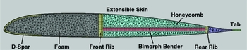
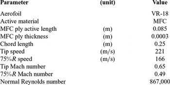
Figure 1 illustrates the CTEF layout used for validation of structure analyses. The aerofoil is the VR-18, a modern helicopter asymmetric aerofoil which has been used in previous ATR studies(Reference Thornburgh, Kreshock and Wilbur6). The aerofoil ends with a tab, which facilitates the attachment of the bimorph bender at the trailing edge. The aerofoil chord size is 250 mm, which was chosen as a full-scale representation of the main rotor blade of a light helicopter, similar to KIOWA(Reference Kim12). Table 1 lists some design parameters of the current model.
CTEF layout of a VR-18 aerofoil for validation of structure analyses.

Design parameters

The CTEF layout consists of a D-shaped nose spar, a bimorph piezoelectric actuator in the trailing edge, an extensible aerofoil skin and core filler materials. The ‘D’ spar is the main load-carrying element which transfers the blade aerodynamic and inertial loads to the rotor hub. It is constructed from E-glass fabric. The bimorph actuator is a rectangular-shaped bender with three MFC plies each on the upper and lower surfaces. Electric fields of opposite direction are applied to the upper and lower MFC layers, respectively, producing extension on one layer and contraction on the other layer. This results in a pure bending of the bimorph bender, which in turn deforms the trailing-edge region. The bimorph bender is attached to the ‘D’ spar at the front end and with a secondary rib spar at the trailing edge. Besides providing actuation, the bimorph bender is the main load carrying element in the aerofoil aft section and transfers the aerodynamic and inertial forces to the forward ‘D’ spar. A nylon material is chosen for the aerofoil skin because of its high compliance. Core filler materials are applied to maintain proper aerofoil shape under aerodynamic pressure and structural loads. Rohacell foam is used inside the ‘D’ spar and Nomex honeycomb is used in the trailing-edge region. Nomex honeycomb has low stiffness chord-wise but large stiffness normal to the chord. The trailing-edge region filled with Nomex honeycomb is easy to bend but difficult to shear, thus maintaining the proper shape under aerodynamic pressure.
The sharp corners present at the connections between the bimorph bender and the blade D-spar and trailing edge are limitations of the current mesher which does automatic FEM meshing of various design layouts. More realistic connections will be studied with manual meshing in MSC/PATRAN once an optimal bimorph layout is attained.
2.1.2 High-fidelity structure analysis
UM/VABS is a finite-element analysis of active cross-sections based on variational-asymptotic methods. It computes the cross-sectional elastic, inertial, thermal and electrical characteristics of active anisotropic beams of arbitrary sectional shape, including the effects of initial twist and curvature. NASTRAN is more capable in modelling complex CTEF layouts with the assistance of MSC/PATRAN pre-/post-processing software(13). In the present study, thermal equivalent analysis was used in all the UM/VABS, NASTRAN and reduced-order models to capture the expansion and contraction of the actuators subjected to an applied electric field(Reference Reaves and Horta14) (UM/VABS, however, can model both piezoelectric actuators and sensors by solving the electro-elastic equations). The cross-section of the CTEF aerofoil is modelled with 2D shell elements with membrane properties in NASTRAN and solved with the linear analysis solution (SOL 101). Identical cross-section discretisation meshes are used for the UM/VABS and NASTRAN models.
2.1.3 Reduced-order analysis
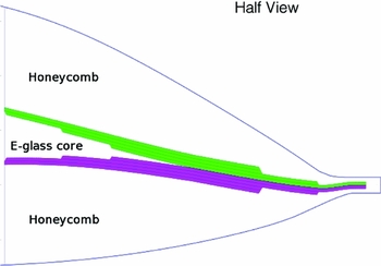
The drawback of using NASTRAN cross-sectional models is that it is challenging to develop a tool that is capable of automatically meshing the cross-section for new design iterations. This makes it difficult to use the modelling technique in an optimisation framework. Thus, a simple analysis solution is needed in order to optimise the bimorph design effectively. The structure forward of the bimorph is designed to be stif; thus, for simplicity, it is assumed to be rigid. The piezoelectric bimorph, along with the core and skin material surrounding it, is modelled as a cantilevered 1D structure. The thickness of each layer of the bimorph, core and skin is then simply defined as a function of chord-wise location. Thus, cross-sectional meshing issues are eliminated. This 1D structure is then used to compute structural deformation, and XFOIL is used to predict aerodynamic coefficients and the pressure distribution on the bimorph. A CTEF layout with MFC stack bimorph bender, as shown in Fig. 2, is then easily and efficiently modelled by this analysis.
Baseline stack MFC layout (length and height not in proportion).

The 1D solution algorithm was developed by taking 2D curvilinear shell equations based on the Sanders-Koiter shell theory, including transverse shear and piezoelectric effects, then collapsing them down to 1D by assuming either plane-stress or plane-strain in the radial direction of the blade. Since the Sanders-Koiter equations include non-linear strains, the resulting model is appropriate for capturing the moderate rotations generated by the bimorph. The camber line of the aerofoil, which is curved for asymmetric aerofoils, was used as the reference surface for the equations. Thus, the outer surface of the aerofoil could be defined solely by the aerofoil thickness as a function of the chord-wise coordinate. This convention was ideal for NACA 4- and 5-digit aerofoils, which define the camber line (yc ) and thickness (yt ) as functions of the chord-wise coordinate. For other aerofoils that are defined by outer surface coordinates, it was necessary to iteratively solve for yc and yt prior to modelling with the new analysis model. The model includes the work done by the aerodynamic pressure and piezoelectric actuation. The non-linear shell equations are solved by using a 1D finite-element method with Hermite shape functions for the out-of-plane displacement and quadratic shape functions for in-plane displacement and transverse shear strain.
2.2 2D aerodynamics analysis
The analyses used to evaluate the aerodynamic characteristics of the CTEF aerofoil are FUN3D, an unstructured-grid CFD code developed at the NASA Langley Research Center(15), 2D OVERTURNS developed at the University of Maryland(Reference Jose, Sitaraman and Baeder16) and XFOIL, a 2D aerofoil analysis using vortex panel method(Reference Drela17).
FUN3D(15,Reference Anderson and Bonhaus18) solves the unsteady Reynolds-averaged Navier-Stokes (RANS) equations on unstructured grids, with several turbulence models available to complete the system of equations. FUN3D is a node-centred code. The code supports mixed-element meshes, in which the nodes may be connected with any combination of prisms, hexahedra, tetrahedra and pyramids. The solver has a variety of mesh-motion options, including rigid, deforming and overset meshes, and a robust implicit time-advancement scheme, which is crucial for rotorcraft applications. FUN3D has previously been applied successfully to rotorcraft simulations using CFD/computational structure dynamics coupling procedures, and validated with UH-60A flight test data(Reference Biedron and Lee-Rausch19).
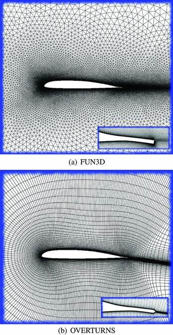
The CFD code, 2D OVERTURNS, is also used to correlate its predictions of aerodynamic characteristics of a CTEF aerofoil with those of the FUN3D. The CFD code solves the compressible RANS equations with proper boundary conditions for the specified geometry on an overset structured mesh. The aerofoil geometry with a deformed CTEF is obtained from the aforementioned 2D structural analyses. This deformed aerofoil is passed to an OVERTURNS grid generator that produces a 329 × 97 C-type grid using a hyperbolic mesh generation technique (Fig. 3). The turbulence model is Spalart-Allmaras.
CFD meshes of a VR-18 aerofoil with continuous trailing-edge flap; Angle-of-Attack = 6°, Mach = 0.49, Reynolds = 867,000, deformed CTEF angle = 8°.

FUN3D can run with both 2D and 3D modules, spanning from incompressible flow to transonic flows. For current CTEF aerofoil simulations, the FUN3D 2D module is used. The 2D unstructured grid is generated with AFLR2(Reference Marcum and P.20). A typical 2D FUN3D unstructured grid and an OVERTURNS structured grid are displayed in Fig. 3. The OVERTURNS C-type grid demands a single trailing-edge point which merges the upper and lower surface, while FUN3D could model the real trailing-edge tab geometry.
XFOIL is adopted as a replacement for CFD and applied in design optimisation, which requires large numbers of calculations. XFOIL uses an inviscid linear-vorticity panel method with Karman-Tsien compressibility correction. The boundary layers and wake are calculated with a two-equation lagged dissipation integral method. It takes an arbitrary aerofoil geometry as input and calculates the aerodynamic coefficients and pressure distribution given Mach number, Reynolds number and angle-of-attack (AoA). The same CTEF aerofoil geometry is used in the CFD codes and the XFOIL analysis.
2.3 Static fluid and structure interaction
The simulation of the fluid and structure interaction uses a simple coupling approach. The CTEF deformation under MFC actuation is first calculated with the reduced-order structure analysis for a given voltage without aerodynamic pressure loads. The deformed CTEF aerofoil is passed to the aerodynamic analyses and the surface aerodynamic pressure is obtained for a given operation condition (fluid properties, AoA, Mach and Reynold’s numbers.) The aerodynamic pressure is, in turn, applied to the CTEF structure model, and the CTEF deformation under both MFC actuation and aerodynamic loading is calculated. This procedure is iterated until convergence is achieved. The criterion for convergence is that the difference in the predicted CTEF deformation between iterations approaches zero. The aerodynamic pressure is calculated on the fluid grids, which is normally different from the structural grids. Linear inter-polation is used to map the aerodynamic loads from the fluid grids to the structural grids.
2.4 Design optimisation procedure
An optimisation procedure is developed to maximise the CTEF actuation authority, i.e. the CTEF deflection angle, by optimally determining critical design variables under certain constraints. The general design variables are bimorph bender geometry and location, aerofoil skin stiffness, core material properties, etc. The general constraints are maximum stresses and strains, cross-sectional CG, centroid and shear centre locations, total weight, etc.
Bender length and location are important variables in determining the aerodynamic characteristics of the CTEF aerofoil, equivalent to the flap chord size in a conventional DTEF aerofoil. A previous study(Reference Shen, Thornburgh, Kreshock, Wilbur and Liu3) determined that a bender located close to the middle of the aerofoil and extending to the trailing edge is optimal in providing maximum pitching moment with low drag (equivalent to a 20% DTEF flap chord.) Thus, the bender location is fixed at 50%c and extended to the trailing edge (98%c).
It has been found that the materials used for the aerofoil skin and core should have as low a stiffness as possible to maximise CTEF deflection. Thus, those materials are chosen with this criteria but also other relevant considerations; that is, the skin material has enough structural durability and stiffness to avoid skin dimpling over core material, and the core material (Nomex honeycomb) has relatively large shear stiffness to maintain the proper shape under aerodynamic pressure. The reduction in aerofoil skin stiffness also lowers the torsional stiffness, which is important for blade aeroelastic characteristics. However, the addition of the bimorph bender compensates, at least in part, the reduction of skin stiffness in providing sufficient blade torsional stiffness.
The only design variable used in the optimisation process is then the bender thickness distribution which affects the CTEF deformation significantly. The optimisation process is also carried out without those general constraints because the capability of predicting them is currently unavailable with the reduced-order analysis. In addition, the main structural component influencing the structural properties of the CTEF aerofoil is the ‘D’ spar. The contribution from the CTEF bender is assumed to be small except the moving of the center of gravity (CG) location, which could be compensated for by using the leading-edge weight. Those general constraints, however, will be verified with the high-fidelity structural analyses, NASTRAN and UM/VABS, in a future study.
The design optimisation procedure is implemented in MATLAB with the ‘fmincon’ function to solve a constrained minimisation problem. The constraints are employed to avoid an unrealistic bender thickness, i.e. negative thickness.
3.0 ANALYSIS VALIDATION AND DESIGN OPTIMISATION
This section first presents the validation of the reduced-order static aeroelastic analysis and then its application in the optimisation of CTEF design. The validation of structural analysis is established by correlation of its predictions with those of NASTRAN and UM/VABS. The accuracy of the adopted aerodynamic analysis, XFOIL, is evaluated by comparing its calculation with those of CFD codes: FUN3D and OVERTURNS. The design optimisation is then carried out with the verified analyses, that is the reduced-order static aeroelastic analysis coupled with XFOIL.
3.1 Structural analysis validation
The accuracy of the reduced-order analysis is established in this section and the important design parameter, bender length, with its effect on CTEF angle is studied. These results used to validate that the structure analysis is obtained without aerodynamics. The coupling of structure and aerodynamic analyses is verified later in the paper.
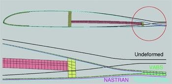
The predicted CTEF deformations of the reduced-order analysis were compared with those of UM/VABS and NASTRAN (Fig. 4). The bimorph bender contains three layers of MFC plies each on the upper and lower surfaces with a thickness of 0.3 mm for each ply. The CTEF deflection is limited by the bimorph bender deformation created by the MFC piezoelectric strain. The aerofoil deformations predicted by the three analyses show reasonably good agreement.
Comparison of the CTEF angles predicted by three structural analyses (core material is removed from the figure for clarity).

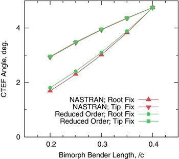
The bimorph bender length is an important design variable, whose effect on CTEF angle is displayed in Fig. 5. The CTEF angle is shown to increase almost linearly with the bender length. The bender length is varied by fixing the bimorph root and varying its tip and vice versa. For the former, the bender root is fixed at 50%c with its tip extending to 90%c for the longest bender. For the latter, the bender tip is fixed at 90%c and with its root extending to 50%c. Again, the CTEF angle predicted by the reduced-order analysis agrees well with NASTRAN calculation for both cases of fixing bimorph root or tip, with largest error of 0.1°. For the same bender length, benders located toward the trailing edge generate a larger CTEF angle. This is because the aerofoil is thinner at the trailing edge, and thus, more flexible.
Variation of CTEF angle with bender length.

3.2 Aerodynamic correlation and evaluation
The goal of an optimal CTEF design is to obtain the maximum aerodynamic pitching moment while maintaining a small drag penalty. The CTEF design has to be evaluated in an aeroelastic analysis because its deflection varies with flight condition as the aerodynamic pressure changes on the trailing-edge flap. Thus, while the computational efficiency of the aerodynamic analysis is important for its utilisation in the optimisation process, its accuracy needs to be sufficient as well. The high-fidelity CFD codes, FUN3D and OVERTURNS, are used to confirm the accuracy of XFOIL.
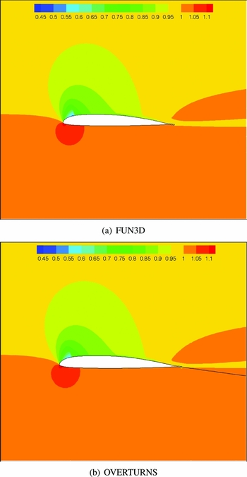
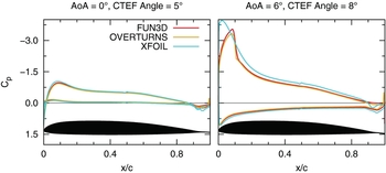
The pressure contours calculated by FUN3D and OVERTURNS are compared in Fig. 6. Good agreement is shown between the predictions of the two codes. The high pressure region above the upper trailing-edge surface predicted by OVERTURNS is slightly more forward than that of FUN3D. This is also displayed as pressure jump at the trailing edge in Fig. 7. Compared with the CFD predictions, the XFOIL predicted Cp shows a large discrepancy at the leading edge but displays relatively good agreement at the middle and trailing-edge sections. Since the aerofoil front section is assumed rigid in the reduced-order analysis, only the pressure in the middle and trailing-edge section affects the predicted CTEF deflections. Thus, XFOIL, with its prediction of the aerodynamic pressure, is considered accurate enough for calculating the CTEF angle. For a low aerodynamic load case with 0° AoA and 5° CTEF angle, Fig. 7 illustrates that good agreement is seen for the complete Cp predictions among all three analyses.
CFD calculation of pressure contour of a VR-18 aerofoil with continuous trailing-edge flap; AoA = 6°, Mach = 0.49, Reynolds = 867,000, deformed CTEF angle = 8°.

Comparison of pressure distributions predicted by FUN3D, OVERTURNS and XFOIL; Mach=0.49.

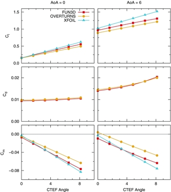
The variation of aerodynamic coefficients with a CTEF angle for two AoAs is illustrated in Fig. 8 (The CTEF angle is varied by changing the input voltage.). At zero AoA, the lift coefficient shows reasonably good agreement among the three analyses; the drag coefficient displays very good agreement between the two CFD codes (XFOIL, with the inviscid option, predicts zero drag as expected of the D’Alembert’s paradox); the pitching moment coefficient is also in good agreement between XFOIL and FUN3D, but not OVERTURNS due to the reason aforementioned in discussing Fig. 7. At an AoA of 5°, the lift coefficient shows a larger deviation among the three analyses, in particular, the XFOIL analysis shows an overall over-prediction, the drag coefficient remains in good agreement between CFD analyses, and the pitching moment coefficient shows relatively good agreement between XFOIL and FUN3D.
Variation of aerodynamic coefficients with a CTEF angle predicted by FUN3D, OVERTURNS and XFOIL; Mach=0.49.

3.3 FSI validation
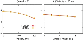
After structural and aerodynamic analyses were verified, respectively, the validation of static aeroelastic analysis was carried out. Figure 9 compares the CTEF angle predicted by the reduced-order analysis coupled with different aerodynamic codes. The CTEF bender is actuated with the same voltage, but aerodynamic loads change with flow speeds and angles of attack. The variation of the CTEF angle with speed shows good agreement between the predictions of XFOIL and FUN3D, with an average difference of 0.05° or error of 1%. Similarly, good agreement is also seen with the variation of the CTEF angle with AoA, which shows an average difference of 0.08° or error of 1%. XFOIL is, thus, considered to provide an accurate enough prediction of aerodynamic load, particularly for the normal aerodynamic load case used in the optimisation. The normal aerodynamic load case is selected with a speed of 166m/s (speed at 75%R at hover) and AoA of 6°. The reduced-order analysis coupled with XFOIL is used in the design optimisation throughout.
Comparison of CTEF angles, predicted by reduced-order analysis, coupled with different aerodynamic codes.

3.4 Design optimisation
The optimisation is applied to two bender configurations: a solid MFC bender and an MFC stack bender. The solid configuration is used to confirm the functioning of the optimisation process and to use its final optimal layout as a reference to the stack bender, the primary design object. The bender is set to be symmetrical about the aerofoil camber line. The optimisation objective is to maximise CTEF actuation authority, that is the maximum CTEF angle under the normal aerodynamic load. The design variable is bender thickness distribution.
The optimal design of several MFC solid benders is presented in Fig. 10, including designs for cases with and without aerodynamic loads. The normal aerodynamic load case is selected with a speed of 166m/s and an AoA of 6°, as mentioned previously. The case of excluding aerodynamics is only presented as a reference to show the effect of aerodynamic load on the optimal bender layout. The full aerofoil is shown first, in correct scale, with the optimal linear bender obtained with aerodynamic loads. The trailing-edge section is displayed next, out of scale, with two optimal bender layouts: one with aerodynamics and the other without. Both layouts are obtained by assuming a linear variation of bender thickness along the length. A thicker bender is obtained when the aerodynamic load is included.
Optimal CTEF geometries of a solid MFC bender.

The detailed bender view is also displayed with optimal configurations obtained with different ways of prescribing bender thickness. The aforementioned linear tapered benders (i.e. linear polynomials) are compared with layouts obtained by prescribing bender thickness with a cubic polynomial and with discrete points (ten equal-distanced locations on the bender). This correlation of bender layouts is to confirm that the bender shape obtained is really the optimum. That all the three optimal shapes converge on each other, for both cases of with and without aerodynamics, respectively, confirms that the optimisation process is functioning, i.e. succeeding in obtaining the optimality (Fig. 10). The linear polynomial layout is very similar to the cubic polynomial layout, thus, could be chosen as the final optimal shape because of its simplicity. The motivation of designing the solid bender in this study, however, is to verify the optimisation process and to use the optimal solid bender as a guideline for the MFC stack bender, the main design object.
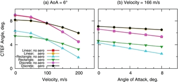
The CTEF angles of the solid benders are compared in Fig. 11. The results of rectangular benders optimised with and without aerodynamics are also present for correlation. It is apparent that the optimised taper bimorph performs much better than a rectangular bender; the linear taper bender with aerodynamics achieves an average 3° or 63% increase in the CTEF angle over that of the rectangular shape bimorph optimised with aerodynamics. Compared among the linear taper benders, the optimal bender optimised under aerodynamic load performs well overall in the range of flow speeds and angles of attack than the bimorph optimised without aerodynamics. Although the bender optimised without aerodynamics generates a larger CTEF angle at speeds lower than 100m/s, the optimal bender with aerodynamics presents a much smaller CTEF reduction rate versus speed and AoA than the optimal bender without aerodynamics. The variations of the CTEF angle with speed and with AoA both compare well between the linear taper bender and the bender optimised with discrete points. This is expected, as the two bender shapes are very close to each other, as shown in Fig. 10.
CTEF angles of the various solid MFC benders under aerodynamic loads.

Since the thickness of the MFC ply is normally fixed, the thickness variations described above are not realistic with MFC. The bimorph benders, instead, need to be constructed with a stack of MFC plies. The empty space between the MFC plies is filled with E-glass core material.
Various tapered MFC bimorph benders, optimised with the normal aerodynamic load case, are displayed in Fig. 12. The complete aerofoil with MFC bender is first shown in proportion, and then the trailing-edge section is displayed with amplification to show the bender in detail. The initial configuration of the stack bender design is shown next, which is selected to resemble the final optimal design based on the geometry of the solid bender. The design variables are the length and shape of the E-glass core and the chord-wise locations of middle plies. The top and bottom plies are fixed at the root and tip of the bender, respectively. The reason is that the optimiser always chooses these locations when they are set to be design variables in the optimisation, thus, they are fixed to reduce the optimisation efforts.
Optimal CTEF layouts of MFC stack bender.

The optimisation is carried out for benders with 2, 3, 4 and 5 plies (counting only half of the bimorph). The results show that all the stack benders converge to a shape similar to the optimal solid bender, being thicker at the root and thinner at the tip. This is attained by having the E-glass core thickness tapering off toward the trailing edge. The two-ply bender has the largest E-glass core while the five-ply bender has the smallest, again to have the MFC plies forming the optimal taper shape as the solid bender. The three-ply bender has the chord-wise location of its middle ply at almost equal distance from the top and bottom plies. The four-ply and five-ply benders have the extra middle plies located close to the bender root.
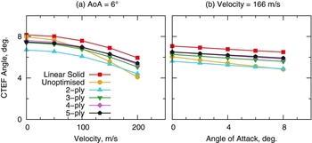
The variation of the CTEF angle with a speed and AoA for various MFC stack benders is displayed in Fig. 13. The results of the optimal solid bender are also presented, which can be seen to be the upper limit of the CTEF angles. The CTEF angles of the unoptimised four-ply MFC stack bender are presented, as well, to show the improvement with optimisation. The two-ply bender generates the lowest CTEF angles among all the optimised layouts for all the presented speeds and angles of attack, while the five-ply bender obtains the largest CTEF angles for all MFC stack benders. The four-ply bender, however, provides CTEF angles almost as large as the five-ply bender, and thus, present itself as potentially the best layout because of its large CTEF angles and relatively less MFC plies.
CTEF angles of the various stack layouts under aerodynamic loads.

The CTEF angle produced by the four-ply optimal layout ranges from 7.6° to 5.3° with speeds from 0 to 200m/s at an AoA of 6°. The reduction in CTEF angle with AoA is less steep than with speed (the first order aerodynamic theory predicts that aerodynamic pressure increases quadratically with speed but linearly with AoA), ranging from 6.5° to 5.8° with an AoA from 0° to 8° at a speed of 166m/s. Compared with the optimal solid bender, the four-ply bender generates an average of 0.62° or 9% less CTEF angle. It produces, however, an average of 0.73° or 14% more CTEF angle than the unoptimised four-ply layout.
The optimal MFC stack CTEF, with its current range of CTEF angles, is able to perform active control applications. Further study, such as a comprehensive rotor analysis, may be, however, required to confirm whether it has sufficient actuation authority to act as primary control devices for swashplateless rotors for the full flight envelope.
4.0 SUMMARY AND CONCLUSIONS
The active continuous trailing-edge flap has been designed and optimised as a potential rotorcraft active control device. Several structural cross-section models are developed: high-fidelity NASTRAN and UM/VABS models and a reduced-order analysis model, developed for optimisation study. The validation of the reduced-order model is established by comparing its predictions of CTEF deformations with those of NASTRAN and UM/VABS analyses, which show good agreement. The 2D aerodynamic characteristics of the CTEF aerofoil are evaluated using CFD analyses: FUN3D and OVERTURNS. XFOIL, coupled with the reduced-order structure model, is adopted for optimisation study. The accuracy of XFOIL in predicting the aerodynamic pressure of the CTEF aerofoil is verified using CFD simulations and shows sufficient fidelity. The predicted variations of aerodynamic coefficients with the CTEF angle are compared among the aerodynamic analyses. The optimisation process is developed and applied to two bimorph bender configurations: an MFC solid bender and an MFC stack bender. The solid configuration is used to confirm the functioning of the optimisation process and to use its optimal layout as a reference to the stack layout, the primary design object. The following concluding remarks were offered, subject to the limitations of the analysis and the scope of this study:
-
1. A linear tapered shape is found to be the optimum for an MFC solid bender, which generates an average of 63% more CTEF angles than those of an optimal rectangular bender.
-
2. The optimised MFC stack bender is shown to resemble the solid bender. A four-ply bimorph is considered the best choice among the stack layouts because of its large output of CTEF angle, relative to the number of plies required.
-
3. The CTEF angle produced by the four-ply optimal layout ranges from 7.6° to 5.3° with speeds from 0 to 200m/s at an AoA of 6°. The reduction in CTEF angle with AoA is less steep than that with speed, ranging from 6.5° to 5.8° with AoA from 0
to 8° at a speed of 166m/s.
-
4. An average of 14% increase in CTEF angles is achieved through optimisation for the four-ply bimorph, compared to the initial layout. However, the CTEF angle is on average 9% less than that generated by the optimal solid bender.
-
5. The optimal MFC stack CTEF, with its current range of CTEF angles, is able to perform active control applications. Further study, such as a comprehensive rotor analysis, however, is required to confirm whether it has sufficient actuation authority to act as primary control devices for swashplateless rotors for the full flight envelope.
ACKNOWLEDGEMENTS
The authors gratefully acknowledge Prof. Carlos Cesnik and his research group at the University of Michigan for assistance on running UM/VABS analysis, and Prof. James Baeder and his group at the University of Maryland on using 2D OVERTURNS.