
1. Introduction
To safely operate and maintain offshore structures in water waves, such as column-based (spar-type) wind turbines or floating platforms, over a long period, the reduction of the wave drift force (time-averaged second-order hydrodynamic force) is essential. In addition, creating a calm and cloaked region on the ocean surface in the presence of surface waves facilitates the installation of these offshore structures. The concept of cloaking objects from incident waves was initially developed for electromagnetic waves (Leonhardt Reference Leonhardt2006; Pendry, Schurig & Smith Reference Pendry, Schurig and Smith2006; Schurig et al. Reference Schurig, Mock, Justice, Cummer, Pendry, Starr and Smith2006). A cloak is a structure that encloses a to-be-cloaked object and results in no reflection or scattering of incident waves from the object. The downstream waves bear no information about the object's presence and the cloaked region is secluded from incident waves. The cloaks proposed for the electromagnetic waves are based on the idea of transformation optics and exploit the form invariance of governing equations. The material properties of the cloak are found using spatial transformations of governing equations. The obtained material properties are usually inhomogeneous and orthotropic and implementing such properties results in the desired trajectory of the incoming waves. Since the only property used in this technique is the form invariance of the governing equations under spatial coordinate transformation, this method has been extended to other areas of physics with form-invariant governing equations, such as acoustics (Chen & Chan Reference Chen and Chan2007; Cummer & Schurig Reference Cummer and Schurig2007; Huang, Zhong & Liu Reference Huang, Zhong and Liu2014; Darabi et al. Reference Darabi, Zareei, Alam and Leamy2018a; Zareei et al. Reference Zareei, Darabi, Leamy and Alam2018), elastic waves (Farhat, Guenneau & Enoch Reference Farhat, Guenneau and Enoch2009; Stenger, Wilhelm & Wegener Reference Stenger, Wilhelm and Wegener2012; Zareei & Alam Reference Zareei and Alam2017; Darabi et al. Reference Darabi, Zareei, Alam and Leamy2018b) or seismic waves (Brûlé et al. Reference Brûlé, Javelaud, Enoch and Guenneau2014). In addition to transformation techniques, an alternative method to achieve cloaking is to minimise the scattering cross-section (or the energy of scattered waves) of an object (Alù & Engheta Reference Alù and Engheta2005). This method has also been successfully applied to different types of waves such as acoustic waves (Guild, Alu & Haberman Reference Guild, Alu and Haberman2011) or water waves (Porter Reference Porter2011; Porter & Newman Reference Porter and Newman2014).
In shallow water, cloaking has been realised using the coordinate transformation technique (Berraquero et al. Reference Berraquero, Maurel, Petitjeans and Pagneux2013; Zareei & Alam Reference Zareei and Alam2015). The governing equation of shallow-water gravity waves is form invariant under the coordinate transformation. The physical parameters controlling wave propagation in shallow water are the sea bed topography and gravitational acceleration (e.g. Berraquero et al. Reference Berraquero, Maurel, Petitjeans and Pagneux2013; Zareei & Alam Reference Zareei and Alam2015). Clearly, varying the gravitational acceleration is unrealistic. The use of nonlinear transformation of a cylindrical region can keep the gravitational acceleration at a constant value, and only change in the sea bed topography is used to achieve cloaking from shallow-water waves (Zareei & Alam Reference Zareei and Alam2015). Alternative approaches are to use an array of bottom-mounted objects for implementing a cloaking device for shallow-water surface gravity waves using the coordinate transformation technique (Dupont et al. Reference Dupont, Guenneau, Kimmoun, Molin and Enoch2016; Iida & Kashiwagi Reference Iida and Kashiwagi2018) or capillary-gravity waves (Farhat et al. Reference Farhat, Enoch, Guenneau and Movchan2008).
As the water depth increases, the effect of the bottom topography exponentially decreases, and as a result, engineered sea bed topography does not affect the wave propagation. In addition, the governing equation of deep-water waves in the potential flow regime is not form-invariant under the coordinate transformation, and therefore it is hard to apply the transformation technique to make a cloak for deep-water waves. To achieve cloaking in a finite depth, a scattering cancellation is proposed (Porter Reference Porter2011; Porter & Newman Reference Porter and Newman2014). Specifically, a sea bed topography is designed to cancel the energy of scattered waves of a bottom-mounted cylinder (Porter & Newman Reference Porter and Newman2014). Multiple floating cylinders (or a ring) are used which shows cloaking performance even for deep-water waves (Newman Reference Newman2014). This cloaking method is validated by numerical computations using a higher-order boundary element method (Iida, Kashiwagi & He Reference Iida, Kashiwagi and He2014) and a model experiment (Iida, Kashiwagi & Miki Reference Iida, Kashiwagi and Miki2016). As an asymmetrical array of the cylinder is utilised, the performance of the cloak depends on the wave direction (Zhang et al. Reference Zhang, He, Wang, Liu, Gou and Liu2019). A concentric annular elastic plate is optimised to reduce the wave drift force (Loukogeorgaki & Kashiwagi Reference Loukogeorgaki and Kashiwagi2019), however, the reduction of the energy of scattered waves is not observed because the plate's flexural rigidity is the only controllable medium property. In addition, because the flexural waves in thin elastic plates are not form invariant (Zareei & Alam Reference Zareei and Alam2017), the floating elastic plate cannot be used for the transformation-based cloaking in deep water.
Here, we present a design of a surface gravity wave cloak achieved through a floating composite elastic plate that surrounds a to-be-cloaked cylinder. The cloaking plate consists of concentric annular plates (axisymmetric, homogeneous and isotropic) that provide required adjustable degrees of freedom to affect and control the propagation direction of waves (see figure 1). Cloaking plate parameters (i.e. number of annular plates, size, flexural rigidity and the mass) are optimised to minimise the energy of scattered waves from the cylinder. We develop here a numerical scheme based on pseudo-spectral and eigenvalue matching methods (Peter, Meylan & Chung Reference Peter, Meylan and Chung2004) to solve this problem, and this is extended to the calculation of the floating composite plate. Next, we use an evolutionary strategy to find the optimum parameters for the plate. Here, we demonstrate deep-water cloaking because cloaking in deep-water waves is especially challenging. We quantify the effectiveness of our cloak and show that the energy of scattered waves is reduced as high as 99.2 % at the target wave number. In addition, we study the effect of different parameters on the optimum solution and show that varying the flexural rigidity is essential to cloaking performance, and the cloaking structure needs to be at least made of four rings with a radius of at least three times of the cloaked cylinder. By quantifying the wave drift force exerted on the cylinder, we show that the optimised plate reduces the drift force by 99.9 % at the target wave number.
Schematic representation of bottom-mounted cylinder and floating composite plate. The plate is assumed elastic and thin. All values are normalised by the radius of the cylinder, wave amplitude, fluid density and gravitational acceleration. The sea bottom is flat at  $z=-h$. Thecomposite plate consists of
 $K$ horizontally concentric annular rings, and the outermost radius of plate is
 $b$. Waves are incident from negative
 $x$-direction (
 $\theta ={\rm \pi}$).

2. Formulation of the problem
2.1. Governing equation and boundary conditions
We consider a bottom-mounted cylinder with radius  $a$ surrounded by a thin elastic composite plate, with its inner radius
 $a$ and outer radius
 $b$, floating on the surface of the water. The plate is composed of
 $K$ concentric annular plates (we call each annular plate a ‘ring’ from here on), and is expected to effectively cloak the cylinder from incident water waves (see figure 1). Adjacent rings are rigidly connected (such as by welding). The plate is always in contact with the free surface, and rings are thin enough such that Kirchhoff's thin plate theory is valid. We number the rings from the outer (ring 1), to the inner (ring
 $K$). The outer radius of ring 1 is denoted by
 $R^{(1)}$, and similarly until the inner radius of the ring
 $K$ which is denoted by
 $R^{(K+1)}$. We consider a Cartesian coordinate system with origin
 $O$ at the centre of the cylinder where
 $z=0$ plane coincides with the undisturbed free surface of the water and the positive
 $z$-axis pointing upward. We assume that the fluid is incompressible, homogeneous, and inviscid, and that the flow is irrotational. Under these assumptions, the linearised governing equation and boundary conditions in terms of the velocity potential
 $\varPhi ({\boldsymbol {x}}, t)$ is
 \begin{gather} \nabla^2\varPhi=0 \quad -h\leqslant z\leqslant 0, \end{gather}
 \begin{gather}\frac{\partial \varPhi}{\partial z}=0 \quad z={-}h, \end{gather}
 \begin{gather}g\frac{\partial \varPhi}{\partial z}+ \frac{\partial^2 \varPhi}{\partial t^2}=0 \quad z=0, r\geqslant b, \end{gather}
 \begin{gather}\left(D^{(k)}\boldsymbol{\nabla}_\perp^4+m_{{p}}^{(k)}\frac{\partial^2}{\partial t^2}+\rho_w g\right) \frac{\partial \varPhi}{\partial z}+\frac{\partial ^2 \varPhi}{\partial t^2}=0 \quad z=0, R^{(k+1)}\leqslant r < R^{(k)}, \end{gather}
where  $g$ is the gravitational acceleration,
 $\rho _w$ is the fluid density,
 $D^{(k)}$ is the flexural rigidity of the
 $k$th ring,
 $m_{{p}}^{(k)}$ is mass per unit area of the
 $k$th ring,
 $\boldsymbol {\nabla }=(\partial /\partial x, \partial /\partial y, \partial /\partial z)$ is the spatial gradient operator, and
 $\boldsymbol {\nabla }_\perp = (\partial /\partial x, \partial /\partial y)$ is the horizontal gradient operator. Subscript
 $p$ denotes the parameters of the plate. Flexural rigidity and mass of the plate are calculated as
 $D^{(k)}=E^{(k)}t_{{p}}^{(k)3}/12(1-\nu ^2)$ and
 $m_{{p}}^{(k)}=\rho _{{p}}^{(k)} t_{{p}}^{(k)}$ where
 $E^{(k)}$ is the
 $k$th ring Young's modulus,
 $\nu$ is the Poisson's ratio and
 $\rho _{{p}}^{(k)}$ and
 $t_{{p}}^{(k)}$ are the density and thickness of the
 $k$th ring, respectively. In these equations, (2.1) is the mass conservation, (2.2) is the kinematic boundary condition on the bottom, (2.3) is a linearised free surface condition and (2.4) is the linearised equation for the
 $k$th ring of the plate. Equation (2.4) is derived assuming that each ring is a thin plate, and is always in touch with the water underneath. Details of derivation and discussion of assumption can be found in Meylan (Reference Meylan2002).
Next, we non-dimensionalise equations (2.1)–(2.4) using the radius of the cylinder  $a$ as the scaling factor in the horizontal direction and the incident wave amplitude
 $\zeta _w$ as the scaling factor for amplitudes. Specifically, we define
 $\bar {x}=x/a$,
 $\bar {t}=t\sqrt {g/a}$, and
 $\bar {\varPhi }=\varPhi /(\zeta _w\sqrt {ag})$. We further assume a harmonic solution in time and, therefore, the velocity potential is expressed by
 $\bar {\varPhi }(\bar {{\boldsymbol {x}}}, \bar {t})={\rm Re}[\bar {\phi }(\bar {{\boldsymbol {x}}})\exp (-{\rm i}\sqrt {\alpha }\bar {t})]$ where
 $\sqrt {\alpha }$ is the dimensionless frequency. Dropping overbars, (2.1)–(2.4) turn into (e.g. Meylan Reference Meylan2002)
 \begin{gather} \nabla^2\phi=0 \quad -h\leqslant z\leqslant 0, \end{gather}
 \begin{gather}\frac{\partial \phi}{\partial z}=0\quad z={-}h, \end{gather}
 \begin{gather}\frac{\partial \phi}{\partial z}-\alpha \phi=0\quad z=0, r\geqslant b, \end{gather}
 \begin{gather}\left(\beta^{(k)}\boldsymbol{\nabla}_\perp^4-\alpha\gamma^{(k)}+1\right) \frac{\partial \phi}{\partial z}-\alpha \phi=0\quad z=0, R^{(k+1)}\leqslant r < R^{(k)}, \end{gather}
where  $\beta ^{(k)}=D^{(k)}/(\rho _wga^4)$ and
 $\gamma ^{(k)}=m_{{p}}^{(k)}/(\rho _w a)$ are dimensionless flexural rigidity and mass of
 $k$th ring, respectively.
2.2. Spectral decomposition of velocity potential
In order to derive a spectral method solution for the above system of equations (i.e. (2.5)–(2.8)), we use the separation of variables to express the velocity potential (e.g. Newman Reference Newman1977) as,
 \begin{equation} \phi(r,\theta,z)=R(r)\varTheta(\theta)Z(z). \end{equation}
Substituting (2.9) into (2.5)–(2.8), the dispersion relations of water waves and elastic waves on the plate are obtained as
 \begin{equation} \alpha=\left\{\begin{array}{@{}ll} k_0\tanh{k_0h} & n=0,\\ -k_n\tan{k_nh} & n> 0, \end{array}\right. \end{equation}
and
 \begin{equation} \frac{\alpha}{\beta^{(k)}\mu_n^{(k)4}-\alpha\gamma^{(k)}+1}=\left\{\begin{array}{ll} \mu_0^{(k)}\tanh{\mu_0^{(k)}h} & n=0,\\ -\mu_n^{(k)}\tan{\mu_n^{(k)}h} & n={-}1,-2, n> 0. \end{array}\right. \end{equation}
Equation (2.10) is the dispersion relation of water waves, where  $k_n$
 $(n=0,1,2,\ldots )$ is the wave number of water waves. The wave number
 $k_n$ in (2.10) has an infinite number of positive and real solutions, where
 $k_0$ denotes progressive waves, and
 $k_1$,
 $k_2\ldots$ correspond to local waves (i.e. evanescent waves). Equation (2.11), on the other hand, is the dispersion relation of elastic waves for the
 $k$th ring of the plate, where
 $\mu ^{(k)}_n$ is the wave number. Similarly, the wave number
 $\mu ^{(k)}_n$ in (2.11) has an infinite number of positive and real solutions
 $\mu ^{(k)}_0,\mu ^{(k)}_1,\mu ^{(k)}_2\ldots$, and additionally two complex solutions
 $\mu ^{(k)}_{-2}$ and
 $\mu ^{(k)}_{-1}$ where
 $\mu ^{(k)}_{-1}=(\mu ^{(k)}_{-2})^*$ and the real parts are positive. Here,
 $\mu ^{(k)}_0$ indicates progressive waves,
 $\mu ^{(k)}_1,\mu ^{(k)}_2\ldots$ are wave numbers of local waves, and
 $\mu ^{(k)}_{-2}$ and
 $\mu ^{(k)}_{-1}$ represent damped waves (e.g. Fox & Squire Reference Fox and Squire1994). Using these dispersion relations, the solutions for
 $Z(z)$ are given as
 \begin{equation} Z(z)=f_n(z)=\left\{\begin{array}{@{}ll} \displaystyle \dfrac{\cosh{k_0(z+h)}}{\cosh k_0h} & n=0,\\ \displaystyle \dfrac{\cos{k_n(z+h)}}{\cos k_nh} & n> 0,\\ \end{array}\right. \end{equation}
and
 \begin{equation} Z(z)=F^{(k)}_n(z)=\left\{\begin{array}{@{}ll} \displaystyle \dfrac{\cosh{\mu^{(k)}_0(z+h)}}{\cosh\mu^{(k)}_0h} & n=0,\\ \displaystyle \dfrac{\cos{\mu^{(k)}_n(z+h)}}{\cos\mu^{(k)}_nh} & n={-}1,-2, n> 0, \end{array}\right. \end{equation}
where  $f_n(z)$ is the
 $z$-function of the water wave region (
 $r\geqslant b$), and
 $F^{(k)}_n(z)$ is the
 $z$-function of the
 $k$th ring region
 $(R^{(k+1)}\leqslant r < R^{(k)})$. Next, the solution for
 $\varTheta (\theta )$ is given as
 $\varTheta (\theta )=\exp (\pm {\rm i}m\theta )$ for
 $m=0,1,\ldots$. Lastly, solutions for
 $r$ are given from Bessel differential equations. As solutions are bound by the radiation condition (i.e. only progressive waves survive at the far-field), the velocity potential of water wave region
 $\phi _w$ is given as
 \begin{equation} \displaystyle
\phi_{w}(r,\theta,z)=\frac{1}{{\rm
i}\sqrt{\alpha}}\sum_{m={-}\infty}^{\infty}\left\{a_{m0}{\rm H}_m^{(1)}
(k_0r)f_0(z)+\sum_{n=1}^\infty a_{mn}{\rm
K}_m(k_nr)f_n(z)\right\}{\rm e}^{{\rm i}m\theta},
\end{equation}
where  ${\rm H}_m^{(1)}({\cdot })$ is the Hankel function of the first kind,
 ${\rm K}_m({\cdot })$ is the modified Bessel function of the second kind and
 $a_{mn}$ is an unknown coefficient of the velocity potential
 $\phi _w$. The coefficient
 $1/{\rm i}\sqrt {\alpha }$ is used for normalising
 $\phi _w$ and that of incident waves. On the other hand, the velocity potential of the
 $k$th ring region
 $\phi _{{p}}^{(k)}$ is
 \begin{align} \displaystyle
\phi_{{p}}^{(k)}(r,\theta,z)&=\frac{1}{{\rm
i}\sqrt{\alpha}}\sum_{m={-}\infty}^{\infty}\left\{b^{(k)}_{m0}{\rm
J}_m(\mu^{(k)}_0r)F^{(k)}_0(z)+\sum_{n={-}2,n\ne 0}^\infty
b^{(k)}_{mn}{\rm
I}_m(\mu^{(k)}_nr)F^{(k)}_n(z)\right\}\nonumber\\
&\quad \left.+\,c^{(k)}_{m0}{\rm H}_m^{(1)}(\mu^{(k)}_0r)F^{(k)}_0(z)+\sum_{n={-}2,n\ne
0}^\infty c^{(k)}_{mn}{\rm
K}_m(\mu^{(k)}_nr)F^{(k)}_n(z)\right\}{\rm e}^{{\rm
i}m\theta}, \end{align}
where  ${\rm J}_m({\cdot })$ is the Bessel function of the first kind,
 ${\rm I}_m({\cdot })$ is the modified Bessel function of the first kind and
 $b_{mn}^{(k)}$ and
 $c_{mn}^{(k)}$ are unknown coefficients. Considering incident waves coming from
 $\theta ={\rm \pi}$ as
 $\eta _{inc}={\rm Re}[\exp ({\rm i}k_0x)\exp (-{\rm i}\sqrt {\alpha }t)]$, the corresponding velocity potential
 $\phi _{inc}$ becomes
 \begin{equation} \phi_{inc}(r,\theta,z)=\frac{1}{{\rm i}\sqrt{\alpha}}{\rm e}^{{\rm i}k_0x}f_0(z)=\frac{1}{{\rm i}\sqrt{\alpha}}\sum_{m={-}\infty}^{\infty}{\rm i}^m{\rm J}_m(k_0r)f_0(z){\rm e}^{{\rm i}m\theta}. \end{equation}
In summary, the solution  $\phi$ to this problem, using the spectral method (e.g. Peter et al. Reference Peter, Meylan and Chung2004), is given as
 \begin{equation} \phi(r,\theta,z)=\left\{\begin{array}{@{}ll} \displaystyle \phi_{inc}+\phi_w & r\geqslant b,\\ \displaystyle \phi_{{p}}^{(k)} & R^{(k+1)}\leqslant r < R^{(k)}. \end{array}\right. \end{equation}
The unknown coefficients  $a_{mn}$,
 $b_{mn}^{(k)}$ and
 $c_{mn}^{(k)}$ are numerically determined to satisfy further boundary conditions. A numerical approach for solving this problem is discussed in the numerical approach section (§ 3).
2.3. Energy of scattered waves at the far-field
The performance of the plate as a cloaking device is quantified by the energy of scattered waves (Iida et al. Reference Iida, Kashiwagi and He2014). To obtain the energy of scattered waves, we consider a control surface  $S_\infty$ at the far-field that surrounds the cylinder and the plate and then calculate the flow of energy passing through this surface. The non-dimensional energy
 $W$ is obtained (Maruo Reference Maruo1960; Kashiwagi, Endo & Yamaguchi Reference Kashiwagi, Endo and Yamaguchi2005) as
 \begin{equation} \displaystyle W={-}\iint_{S_\infty}\overline{\frac{\partial \varPhi}{\partial t}\frac{\partial \varPhi}{\partial n}}{\rm d}S \simeq{-}\int_{{-}h}^0{\rm d}z \int_0^{2{\rm \pi}}\overline{\frac{\partial \varPhi}{\partial t}\frac{\partial \varPhi}{\partial r}}r\,{\rm d}\theta. \end{equation}
As the control surface is far from the cylinder and the plate, local waves created by structures are fully attenuated, and as a result, the velocity potential at far-field  $\varPhi _{far}$ becomes
 \begin{equation} \varPhi_{far}(r,\theta,z,t) = {\rm Re} \left[ \phi_{far}(r,\theta,z){\rm e}^{-{\rm i} \sqrt{\alpha} t} \right], \end{equation}
where
 \begin{equation} \phi_{far}(r,\theta,z) = \frac{1}{{\rm i} \sqrt{\alpha}} \sum_{m={-}\infty}^{\infty} \left\{ {\rm i}^m{\rm J}_m(k_0r)+a_{m0}{\rm H}_m^{(1)}(k_0r)\right\}f_0(z) {\rm e}^{{\rm i}m\theta}. \end{equation}
Substituting (2.19) into (2.18), we find the energy
 \begin{align} W&={-}\frac{{\rm
i}k_0}{8C_0\sqrt{\alpha}}\int_0^{2{\rm \pi}}
\sum_{p={-}\infty}^\infty\sum_{q={-}\infty}^\infty
\left\{\left( ({-}{\rm i})^q{\rm
J}_q+a_{q0}^*{\rm H}_q^{(2)}\right)\left({\rm i}^p{\rm J}_p'+a_{p0}
{\rm H}_p^{(1)'}\right) \right.\nonumber\\
&\quad\left.-\,\left({\rm i}^p{\rm J}_p+a_{p0}{\rm H}_p^{(1)}\right)\left(({-}{\rm i})^q{\rm
J}_q'+a_{q0}{\rm H}_q^{(2)'} \right) {\rm e}^{{\rm i}p\theta}{\rm
e}^{-{\rm i}q\theta}\right\}r\,{\rm d}\theta,
\end{align}
where
 \begin{equation} C_0=\frac{k_0^2}{\alpha+(k_0^2-\alpha^2)h}. \end{equation}
Note that the orthogonal relations and Wronskian formulae are (see Abramowitz & Stegun Reference Abramowitz and Stegun1964; Kashiwagi & Yoshida Reference Kashiwagi and Yoshida2001)
 \begin{gather} \int_0^{2{\rm \pi}}{\rm e}^{{\rm i}p\theta}{\rm e}^{-{\rm i}q\theta}\,{\rm d}\theta=2{\rm \pi} \delta _{pq}, \end{gather}
 \begin{gather}\left\{\begin{array}{@{}l}
\displaystyle {\rm J}_m{\rm H}_m^{(1)'}-{\rm J}_m'{\rm
H}_m^{(1)}=\dfrac{2{\rm i}}{{\rm \pi} k_0r},\\ \displaystyle
{\rm J}_m'{\rm H}_m^{(2)}-{\rm J}_m{\rm H}_m^{(2)'}=\dfrac{2{\rm
i}}{{\rm \pi} k_0r},\\ \displaystyle {\rm H}_m^{(1)'}{\rm H}_m^{(2)}-{\rm
H}_m^{(1)}{\rm H}_m^{(2)'}=\dfrac{4{\rm i}}{{\rm \pi} k_0r},
\end{array} \right. \end{gather}
where  $\delta _{pq}$ is the Kronecker delta. Using (2.23) and (2.24), we can simplify the energy term to
 \begin{equation} W=\frac{1}{C_0\sqrt{\alpha}}\sum_{m={-}\infty}^\infty\left\{\text{Re} [{\rm i}^m a_{m0}^*]+|a_{m0}|^2 \right\}=0. \end{equation}
The expression for  $W$ is the energy balance equation and thus it must be identically zero (we later use this equation for the validation of our numerical scheme in Appendix B). Note that because
 $a_{m0}$ is the amplitude of scattered waves, the second term in (2.25) indicates the energy transferred to scattered waves. As a result, the energy of scattered waves
 $W_s$ is given as
 \begin{equation} W_s=\frac{1}{C_0\sqrt{\alpha}}\sum_{m={-}\infty}^\infty|a_{m0}|^2. \end{equation}
The energy of scattered waves obtained here (2.26) is equal to the form of the Kochin function in Newman (Reference Newman2014). We define the cloaking factor  $\mathcal {F}_{clk}$ by the ratio of the energy of scattered waves of the cylinder with the cloak
 $W_{clk}$ to that of the isolated cylinder
 $W_{cyl}$ (Porter & Newman Reference Porter and Newman2014), i.e.
 \begin{equation} \mathcal{F}_{clk}=\frac{W_{clk}}{W_{cyl}}. \end{equation}
If  $\mathcal {F}_{clk}<1$, then the energy scattered by the cylinder is decreased by the cloak and clearly, the perfect cloaking is achieved as
 $\mathcal {F}_{clk}=0$.
To evaluate the cloaking performance with angular directions, a scattering coefficient is also introduced. The complex amplitude of the progressive component of scattering waves is given as
 \begin{equation} \zeta_{ps}(r,\theta)=\sum_{m={-}\infty}^\infty\sum_{n=1}^\infty a_{m0}{\rm H}_m^{(1)}(k_0 r){\rm e}^{{\rm i}m\theta}. \end{equation}
Then, the ratio of the amplitude of the cylinder with the cloak  $|\zeta _{clk}(b,\theta )|$ to that of the isolated cylinder
 $|\zeta _{cyl}(1,\theta )|$, namely a scattering coefficient
 $\mathcal {S}_{clk}$, is defined as
 \begin{equation} \mathcal{S}_{clk}(\theta)=\frac{|\zeta_{clk}(b,\theta)|}{|\zeta_{cyl}(1,\theta)|}, \end{equation}
where these amplitudes are given at the outermost water line of the structures.
Next, we calculate the wave drift force acting on the cylinder. The wave drift force is the time-averaged second-order hydrodynamic force calculated by the first-order velocity potential. Considering the control surface at the far-field, the wave drift force can be calculated by the momentum conservation principle (Maruo Reference Maruo1960) as
 \begin{equation} \overline{F_x}=\overline{\iint_{S_H}pn_x\,{\rm d}S}={-}\overline{\iint_{S_\infty}\left(pn_x+\frac{\partial \varPhi}{\partial x}u_n\right){\rm d}S}, \end{equation}
where  $\overline {F_x}$ is the non-dimensional wave drift force,
 $S_H$ is the surface of the body,
 $p$ is pressure,
 $n_x$ is the
 $x$-component of the normal vector and
 $u_n$ is the velocity in the direction of the normal vector. Using similar analytical expansion to the energy of scattered waves, the formula for the wave drift force is obtained (Kashiwagi & Yoshida Reference Kashiwagi and Yoshida2001) as
 \begin{equation} \overline{F_x}= \frac{k_0}{2C_0\alpha}\sum_{m={-}\infty}^{\infty}\text{Im}[2a_{m0}a^*_{m+1,0}+{\rm i}^ma^*_{m+1,0}+({-}{\rm i})^{m+1}a_{m0}]. \end{equation}
As the wave drift force is calculated by the amplitude of scattered waves  $a_{m0}$, the wave drift force acting on bodies becomes very small when there is no scattered wave.
3. Numerical approach
The spectral solution (i.e. (2.14) and (2.15)) to this problem (2.5)–(2.8) has unknown coefficients (i.e.  $a_{mn}$,
 $b_{mn}^{(k)}$ and
 $c_{mn}^{(k)}$) that can be found by satisfying the boundary conditions. At first, we approximate the solution by truncating the infinite number of modes in (2.17) to orders
 $M$ and
 $N$ for azimuthal and radial terms, respectively. The numbers
 $M$ and
 $N$ are decided such that the solution is converged and the results do not change by increasing
 $M$ and
 $N$ any further. For each azimuthal mode, we have
 $N+1$ unknowns in the water wave region (i.e.
 $a_{mn}$ for
 $n=0,1,2,\ldots,N$), and
 $2K(N+3)$ unknowns in the plate region (i.e.
 $b^{(k)}_{mn}$ and
 $c^{(k)}_{mn}$ for
 $k=1,2,\ldots,K$ and
 $n=-2,-1,0,1,\ldots,N$). In total, the number of unknown coefficients is
 $N+1+2K(N+3)$, and thus the same number of boundary conditions are required to solve the problem.
We utilise an eigenvalue matching method (Peter et al. Reference Peter, Meylan and Chung2004) to determine the unknown coefficients. The form of the velocity potential in (2.17) depends on the radial direction  $r$, and matching of each quantity at the boundaries should be considered. Since these matching boundary conditions are valid throughout the depth,
 $z$-function
 $f_\ell (z)$
 $(\ell =0,1,\ldots,N)$ is selected as a set of basis functions. These functions are multiplied by the velocity potential, and these are integrated throughout the water depth. Resultant functions with respect to
 $z$ are defined as
 \begin{gather} A_{n\ell} \equiv \int_{{-}h}^{0} f_n(z) f_\ell(z) \,{\rm d} z =\frac{1}{2}\left( \frac{\cos{k_nh}\sin{k_nh}+k_nh}{k_n\cos^2{k_nh}}\right)\delta_{n\ell}, \end{gather}
 \begin{gather}B_{n\ell}^{(k)} \equiv \int_{{-}h}^{0} F_n^{(k)}(z)f_\ell(z) \,{\rm d} z= \frac{k_\ell\sin{k_\ell h}\cos{\mu_n^{(k)}h}-\mu_n^{(k)}\cos{k_\ell h}\sin{\mu_n^{(k)}h} }{(k_\ell^2-\mu_n^{(k)2})\cos{k_\ell h}\cos{\mu_n^{(k)}h}}. \end{gather}
Note that wave numbers in (3.1) and (3.2) must be replaced as  $k_0\to {\rm i}k_0$ and
 $\mu _0^{(k)}\to {\rm i}\mu _0^{(k)}$ when
 $n=0$. Using (3.1) and (3.2) for each boundary condition, the number of conditions becomes
 $N+1$. Next, we need to satisfy the following boundary conditions.
(i) Matching conditions of the velocity potential between the free surface and the plate (
 $N+1$ equations).
(ii) Matching conditions of the radial derivative of the velocity potential between the free surface and the plate (
$N+1$ equations).(iii) Matching conditions of the velocity potential between adjacent rings (
$(K-1)(N+1)$ equations).(iv) Matching conditions of the radial derivative of the velocity potential between adjacent rings (
$(K-1)(N+1)$ equations).(v) No flux conditions at the surface of the cylinder (
$N+1$ equations).(vi) Matching conditions of the wave elevation between adjacent rings (
$K-1$ equations).(vii) Matching conditions of the radial derivative of the wave elevation between adjacent rings (
$K-1$ equations).(viii) Matching conditions of the bending moment between adjacent rings (
$K-1$ equations).(ix) Matching conditions of the shear force between adjacent rings (
$K-1$ equations).(x) Free–free beam conditions; zero bending moment and shear force (4 equations).


Here, the plate is not fixed to the cylinder, and the inner edge of the plate vertically moves with the free surface. We assume no gap between the cylinder and the plate. In practice, as long as the gap is small compared with the width and the thickness of the innermost ring, the analysis is still valid. This may be achieved through the use of sliders or lubricated bushings. Here, we neglect friction between the innermost ring and the cylinder.
Matching the list of boundary conditions, we obtain  $N+1+2K(N+3)$ equations which are the same as the number of unknowns. Solving these equations, all unknown coefficients are found. Details of these boundary conditions are given in Appendix A. For completeness here, we calculate the bending moment
 $M^{(k)}_r$ and equivalent shear force
 $V^{(k)}_r$ on the plate using the surface elevation of the plate. These quantities for the radial direction acting on the
 $k$th ring are given as
 \begin{gather} M^{(k)}_r (r, \theta, t) = \text{Re}\left[\sum_{m={-}\infty}^{\infty} \mathcal{M}_m^{(k)}(r) {\rm e}^{{\rm i}m\theta}{\rm e}^{-{\rm i}\sqrt{\alpha} t} \right], \end{gather}
 \begin{gather}V^{(k)}_r (r, \theta, t) = \text{Re}\left[\sum_{m={-}\infty}^{\infty} \mathcal{V}_m^{(k)}(r) {\rm e}^{{\rm i}m\theta} {\rm e}^{-{\rm i}\sqrt{\alpha} t} \right], \end{gather}
where  $\mathcal {M}_m^{(k)} (r)$ and
 $\mathcal {V}_m^{(k)} (r)$ are written as
 \begin{gather} \mathcal{M}_m^{(k)} (r) ={-}\left[ \boldsymbol{\nabla}^2_\perp{-}\frac{1-\nu}{r}\left( \frac{\partial}{\partial r} -\frac{m^2}{r} \right) \right] \psi^{(k)}(r), \end{gather}
 \begin{gather}\mathcal{V}_m^{(k)}(r) ={-}\left[ \frac{\partial}{\partial r}\boldsymbol{\nabla}^2_\perp{-}m^2\frac{1-\nu}{r^2}\left( \frac{\partial}{\partial r} - \frac{1}{r} \right) \right] \psi^{(k)}(r). \end{gather}
In these equations, note that
 \begin{align} \psi^{(k)}(r)&=b^{(k)}_{m0}G^{(k)}_0{\rm J}_m(\mu^{(k)}_0r)+\sum_{n={-}2,n\ne 0}^\infty b^{(k)}_{mn}G^{(k)}_n{\rm I}_m(\mu^{(k)}_nr)\nonumber\\ &\quad +c^{(k)}_{m0}G^{(k)}_0{\rm H}_m^{(1)}(\mu^{(k)}_0r)+\sum_{n={-}2,n\ne 0}^\infty c^{(k)}_{mn}G^{(k)}_n{\rm K}_m(\mu^{(k)}_nr), \end{align}
where
 \begin{equation} G_n^{(k)}=\frac{\beta^{(k)}}{\beta^{(k)}\mu_n^{(k)4}-\alpha \gamma^{(k)}+1}.\end{equation}
4. Evolutionary optimisation of the plate
Our goal here is to cancel the energy of scattered waves from the cylinder by optimising the floating plate parameters. In other words, we optimise the parameters of the plate to minimise the energy of scattered waves. We use an evolutionary optimisation method, specifically, the real-coded genetic algorithm (RGA) based on the unimodal normal distribution crossover and minimal generation gap (Ono, Kita & Kobayashi Reference Ono, Kita and Kobayashi1999). One motivation behind the choice of a meta-heuristic approach for the optimisation is that the gradient of energy with respect to the optimising parameters becomes complex and tedious to work with, and also we avoid getting trapped in potential local minima. We rewrite the problem here as
 \begin{equation} \begin{array}{lll} {\rm minimise} & W_{clk}, & \\ {\rm subject\ to} & 0.01\leqslant \beta^{(k)}\leqslant 0.5 & k=1,2,\ldots,K,\\ & 0.01\leqslant \gamma^{(k)}\leqslant 0.5 & k=1,2,\ldots,K, \end{array} \end{equation}
where optimum non-dimensional flexural rigidity  $\beta ^{(k)}$ and mass
 $\gamma ^{(k)}$ are sought under selected numerical conditions: the wave number
 $k_0$, the water depth
 $h$, the outermost radius of the plate
 $b$, the number of rings
 $K$ and the Poisson's ratio of the plate
 $\nu$. Note that we set a constant value of the Poisson's ratio as cloaking can be achieved even if we assume it. The minimisation is done at a certain wave number of incident waves. The termination condition is based on the upper limit on the number of generations (usually
 $O(10{,}000)$), and several optimisations with different number of generations are performed to ensure the convergence of the result.
5. Results and discussion
To show the effectiveness of the proposed cloak, numerical simulations are carried out. As the cloaking in deep water is a challenge due to the absence of the water depth effect, we demonstrate the cases of deep-water waves. To assume deep-water waves throughout frequencies,  $h/\lambda =1.0$ is considered where
 $\lambda$ is the wavelength. We fix the Poisson's ratio of the plate
 $\nu =0.25$ and also consider the same radial width for each ring of the composite plate, i.e.
 $R^{(k)}-R^{(k+1)} = \text {const.}$,
 $k=1,2,\ldots, K$ where
 $K$ is the total number of the plate's rings. Here, we aim to cloak the cylinder at the wave number
 $k_0=1.0$. The energy of scattered waves of the isolated cylinder at this wave number is
 $W_{cyl}=0.500$. To suppress this energy, we optimise plate parameters, i.e. flexural rigidity
 $\beta ^{(k)}$ and mass
 $\gamma ^{(k)}$, using an evolutionary strategy (§ 4). In order to optimise the plate parameters, we consider three different cases: (1) optimising both flexural rigidity
 $\beta ^{(k)}$ and mass
 $\gamma ^{(k)}$ for all of the rings of the plate
 $(k=1,2,\ldots,K)$, which we call case I; (2) optimising the flexural rigidity for each ring of the plate (
 $\beta ^{(k)}$,
 $k=1,2,\ldots,K$) while keeping the mass as a constant for all rings (i.e.
 $\gamma ^{(k)}=\gamma ^{(1)},$
 $k=2,3,\ldots,K$), which we denote as case II; and, lastly, (3) optimising mass of the plate for each ring of the plate (
 $\gamma ^{(k)}$,
 $k=1,2,\ldots,K$) while keeping the flexural rigidity as a constant for all rings (
 $\beta ^{(k)}=\beta ^{(1)},$
 $k=2,3,\ldots,K$), which we call case III.
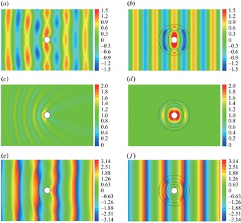
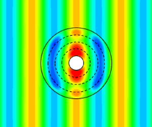
First, we visualise the wave field around an isolated cylinder and also a cylinder with the optimised plate surrounding it (figure 2). The optimised plate shown in figure 2 consists of  $K=4$ rings with the outermost radius
 $b=5.0$, where both flexural rigidity and the mass of the plate are optimised to minimise the energy of scattered waves (case I). The optimised plate yields
 $W_{clk}=0.004$, with a cloaking factor of
 $\mathcal {F}_{clk}=0.008$. The comparisons of wave patterns between the isolated cylinder (left column) and the cloaked cylinder (right column) are shown. The real parts of the wave elevation around the cylinder are shown in figures 2(a) and 2(b), the amplitudes of the wave elevation are shown in figures 2(c) and 2(d), and the phases of wave elevation are shown in figures 2(e) and 2(f). In contrast to the isolated cylinder which generates outgoing scattered waves, the cylinder with the optimised plate has no visually identifiable outgoing wave in the wave amplitudes field around it (figure 2c,d). Similarly, we observe that the isolated cylinder modulates the wave phase field, however, the cylinder with the plate has a phase field that matches that of incident waves. As the wave amplitude and phase at the plate are almost symmetric with respect to the
 $y$-axis, it yields an almost zero wave drift force (we quantify the forces exerted on the cylinder later in this section). As a result, the optimised floating composite plate is significantly reducing the energy of scattered waves of water waves and cloaking the cylinder from the incident wave. It is noted that because the cloaking plate here is axisymmetric, its functionality is independent of incoming waves’ direction and as a result, is omnidirectional.
The real part (a,b), amplitude (c,d) and phase field (e,f) of the wave solution for an isolated cylinder (a,c,e) and the cylinder surrounded by the optimised plate (b,d,f). The optimised composite plate consists of  $K=4$ rings where the flexural rigidity and mass of each ring are optimised to minimise the energy of scattered waves for the wave number
 $k_0=1.0$, i.e. case I.

Next, we investigate the effect of the number of rings  $K$ on the effectiveness of the cloaking plate. We fix the outermost radius of the plate at
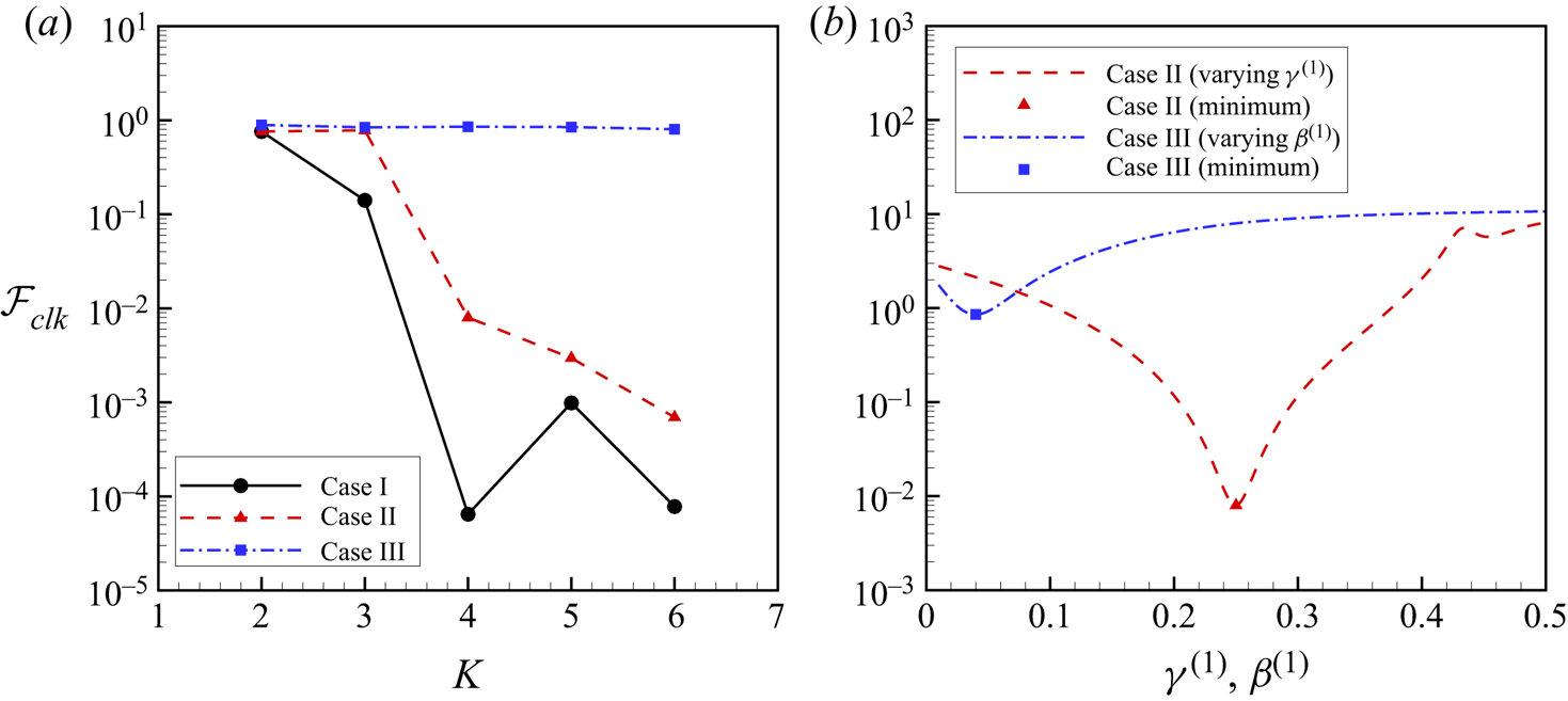
 $b=5.0$ and we plot the cloaking factor versus the number of rings for the optimised plate for the three cases (I, II and III) in figure 3(a). Interestingly, when the ring number is
 $K\geqslant 4$, the cloaking factors in cases I and II become less than 0.01. However, the cloaking factor in case III does not decrease significantly and the cloaking factor remains above 0.8. As a result, varying flexural rigidity
 $\beta ^{(k)}$ is essential for manipulating waves and creating a cloaking plate. As case I has a cloaking factor smaller than case II, optimising the mass
 $\gamma ^{(k)}$ helps to achieve a better cloak, nevertheless only optimising the mass is insufficient to realise an effective cloaking plate. The use of larger
 $K$ does not always yield a smaller cloaking factor as seen in the result of
 $K=5$ in case I. To investigate the sensitivity of the cloaking factor to the flexural rigidity and mass, we calculate the cloaking factor while modulating these parameters. The sensitivity of the factor to these parameters is shown in figure 3(b). The result of case II against varying mass
 $\gamma ^{(1)}$, and that of case III against varying flexural rigidity
 $\beta ^{(1)}$ are plotted; optimum values are marked by a square and triangle, respectively. The cloaking factor for case II increases as the mass
 $\gamma ^{(1)}$ slightly changes from the optimum value. When the mass
 $\gamma ^{(1)}$ and flexural rigidity
 $\beta ^{(1)}$ are far from the optimum values, the cloaking factors are bigger than 1.0, meaning that the structure scatters waves with an energy larger than that of the isolated cylinder. It can be concluded that the cloaking factor is sensitive to both flexural rigidity and mass of the plate, and a large deviation can be detrimental to the efficacy of the cloaking plate.
(a) Comparison of cloaking factor  $\mathcal {F}_{clk}$ versus the number of rings
 $K$ for: case I when both flexural rigidity and mass are optimised for each ring of the composite plate; case II when the flexural rigidity is optimised for each ring while the mass stays as a constant for all rings; and case III, when the mass is optimised on every ring while the flexural rigidity remains a constant for all rings. (b) Sensitivity study of cloaking factor to flexural rigidity and mass for a plate with
 $K=4$ rings for case II with varying mass
 $\gamma ^{(1)}$ and case III with varying flexural rigidity
 $\beta ^{(1)}$. Note that the red triangle/blue square in (b) correspond to the values of the red/blue curve for
 $K=4$ in (a)

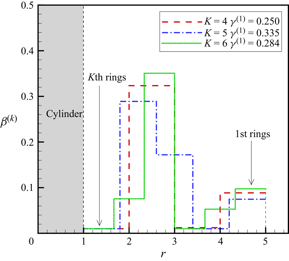
The spatial distribution of the flexural rigidity in case II is shown in figure 4 where it shows the structural flexural rigidity profile of the composite plate. Note that  $r\leqslant 1.0$ is the cylinder region; the plate is at
 $1.0\leqslant r\leqslant 5.0$. Results for
 $K=4$,
 $5$ and
 $6$ are plotted and fixed values of mass are noted in the legend. For
 $K=4$, the plate has two sets of peaks and valleys with the first peak being larger than the second. The values of valleys are almost at
 $\beta = 0.01$ which is the lower limit of the physical parameter (see (4.1)). Interestingly, the rigidity profile follows a similar trend for the different number of rings. The two sets of peaks and valleys are not achievable with only three rings, and this might be the reason why cloaking cannot be achieved for
 $K<4$ (see figure 3a).
Spatial distributions of flexural rigidities  $\beta ^{(k)}$ for the optimised composite plate. The plate extends at
 $1.0\leqslant r\leqslant 5.0$ where the cylinder is inside
 $r\leqslant 1.0$. We assume a constant mass density across the rings, and variable flexural rigidity (case II). We optimise the composite plate parameters for the different number of rings
 $K=4$,
 $5$ and
 $6$. The value found for the optimised
 $\gamma$ is noted in the legend, and the flexural rigidity profile is plotted across the rings.

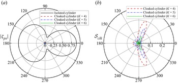
To investigate the cloaking performance with angular directions, the amplitude of progressive scattering waves and scattering coefficient against angle are shown in figure 5. Results of case II with ring numbers  $K=4$,
 $5$ and 6 are plotted. Compared with the isolated cylinder, the cylinder with the plate of all ring numbers show remarkably small progressive scattering wave amplitude. Figure 5(b) indicates that scattering coefficients are rose-like shapes. Sizes of petals are the biggest around
 $\theta =\pm 0.4 {\rm \pi}\ (=\pm 72^\circ )$ because the progressive scattering wave amplitude by the isolated cylinder at this angle is relatively smaller than those of other angles. Here
 $K=4$ has only 3 petals, whereas
 $K=5$ and
 $K=6$ have 10 petals.
(a) Amplitude of progressive component of scattering waves  $|\zeta _{ps}|$ and (b) scattering coefficient
 $\mathcal {S}_{clk}$ against angle. Incident waves come from
 $\theta ={\rm \pi}$. The outermost radius of the plate
 $b=5.0$ and parameters of case II (mass
 $\gamma ^{(k)}$ being constant across rings whereas
 $\gamma ^{(1)}$ can vary) are considered with the number of rings
 $K=4$,
 $5$ and 6.

In addition to the number of rings, we analyse the influence of the outermost radius  $b$ on the cloaking factor. The cloaking factor for case II against the outermost radius
 $b$ is shown in figure 6. When the outermost radius is
 $b=2.0$, the factor is not fully reduced even with increasing the number of rings
 $K$. The cloaking factor for
 $K=4$ and
 $b=6.0$ is also not small enough, while results of
 $K=5$ and
 $6$ are less than 0.01. When
 $b=4.0$ and 5.0, the use of the larger ring number helps us to achieve a smaller cloaking factor whereas
 $b=6.0$ does not show such a result. In summary, it is observed that the size of the plate
 $b$ affects the cloaking factor and cloaking cannot be realised using a small plate size. In addition, using a bigger plate size does not necessarily indicate a better cloaking result. An optimised plate size and ring number exist that should be selected for efficient cloaking. In other words, our simulation results suggest that for a given plate size, there is an optimum number of rings, and for a given number of rings, there is an optimum value for the outer diameter of the cloaking plate.
Cloaking factor  $\mathcal {F}_{clk}$ against sizes of outermost radius
 $b=2.0,3.0,4.0,5.0$ and 6.0. Case II (mass
 $\gamma ^{(k)}$ is constant as
 $\gamma ^{(1)}$ for all rings) is considered. Figure is displayed on semi-log graph. The influence of outermost radius size on cloaking factor is investigated using different ring numbers
 $K=4$,
 $5$ and 6. Note that zero cloaking factor
 $\mathcal {F}_{clk}=0$ yields perfect cloaking.

Lastly, we analyse the frequency response of the cloaking plate, i.e. the behaviour of the structures for wave numbers or wave frequencies other than the value that it is optimised for. For all frequencies, deep water is assumed using  $h/\lambda =1.0$. Energy balance in wave numbers is discussed in Appendix B to demonstrate the numerical accuracy. Here, the energy of scattered waves is shown in figure 7(a), and the wave drift force acting in
 $x$-direction is shown in figure 7(b). The result of the isolated cylinder and the results of the cloaked cylinder are compared. The outermost radius of the plate is fixed at
 $b=5.0$, and physical parameters in case II are used. Looking at
 $k_0=1.0$, the wave drift force of the isolated cylinder is
 $\overline {F_x}|_{cyl}=1.330$ and the cloaked wave drift forces by different
 $K$ are
 $\overline {F_x}|_{K=4}=0.010$,
 $\overline {F_x}|_{K=5}=0.004$ and
 $\overline {F_x}|_{K=6}=0.001$; 99.9 % reduction of wave drift force is achieved at most. Therefore, both energy of scattered waves and wave drift force are dramatically reduced and become almost zero using the composite plate at the target wave number
 $k_0=1.0$. Note that the wave drift force is the second-order force based on the law of action and reaction of wave scattering. As a result, the wave drift force is not acting on the structures if no scattered wave is generated, or if the scattered-wave field is
 $y$-symmetric as shown in figure 2(b). As for frequency responses, the drift force of the cloaked cylinder is smaller than that of the isolated cylinder around the target wave number with a bandwidth of
 $\Delta k=0.5$ (in the case of
 $K=4$). However, these values are larger than those of the isolated cylinder outside this band, meaning that the energy scattered by the structures is larger than that of the isolated cylinder. Note that the energy of scattered waves and the wave drift force converge as
 $k_0\to 0$ and
 $k_0\to 2.0$. Interestingly, using a larger number of rings
 $K$ does not indicate a smaller wave drift force for the frequency bands. For realising an optimised cloak in a frequency band, the integration of the cloaking factor over the frequency band (i.e.
 $\int _{\Delta k}\mathcal {F}_{clk}dk$) might be used as a new objective function (e.g. Bobinski et al. Reference Bobinski, Maurel, Petitjeans and Pagneux2018) instead of the cloaking factor at one frequency. As we can increase the degrees of freedom for controlling wave propagation by easily increasing the number of rings in the composite plate, such plate design can potentially achieve a broadband cloak from water waves.
(a) Energy of scattered waves  $W_s$ and (b) wave drift force in
 $x$-direction
 $\overline {F_x}$ against wave number
 $k_0$. Figures are displayed on semi-log graph. Results are compared among the isolated cylinder and the cylinder with the optimised plate. Here, the outermost radius of the plate is
 $b=5.0$. We consider case II (mass
 $\gamma ^{(k)}$ being constant across rings whereas
 $\gamma ^{(1)}$ can vary) with the number of rings
 $K=4$,
 $5$ and 6. Plate parameters are optimised to minimise the energy of scattered waves at wave number
 $k_0=1.0$.

We would like to briefly comment here that the range of parameters in (4.1) is chosen such that the associated physical parameters fall within typical values of realistic materials. For instance, for a fluid density of  $\rho _w=1000\ {\rm kg}\ {\rm m}^{-3}$, gravitational acceleration of
 $g=9.81\ {\rm m}\ {\rm s}^{-2}$, the radius of the cloaked cylinder
 $a=1.0$ m and the thickness of the plate
 $t_p=0.1$ m, then the range of
 $0.01\leqslant \beta ^{(k)} \leqslant 0.5$ corresponds to a Young's modulus between 1 and 50 GPa.
We also would like to comment that the presented investigation is based on the linear potential theory, whereas real ocean waves can be very steep and highly nonlinear. If the proposed idea is to be considered for real ocean scenarios, then a thorough investigation of the effect of nonlinearities must be performed. An analytical leading-order nonlinear analysis is an immediate extension of the present study. Nevertheless, for a full-nonlinear analysis, resorting to direct simulations may be the only practical option. For either analyses, our results can serve as an initial configuration and a starting point for more general optimisations and in-depth investigations.
6. Conclusion
We have presented the cloaking of a bottom-mounted cylinder from water waves using an elastic plate floating on the surface around the cylinder. In the governing equation of surface gravity waves, the sea bed topography and the gravitational acceleration are the only physical parameters controlling the trajectory of wave propagation; nevertheless, the effect of sea depth exponentially decreases as the depth increases, and the gravitational acceleration is a physical constant. As a consequence, the cloaking of the offshore structure from deep-water waves becomes a challenge. Here, we have proposed the use of a floating composite plate to provide extra adjustable degrees of freedom for controlling wave propagation. The composite plate consists of  $K$ concentric annular rings with isotropic and homogeneous physical parameters. This design enables easier experimental implementation. The cloak is created based on the scattering cancellation method; the plate cancels out the scattered waves from the cylinder. Physical parameters of each ring are optimised using an evolutionary strategy method, specifically a real-coded genetic algorithm. A numerical calculation scheme is developed using pseudo-spectral and eigenvalue matching methods, and the effectiveness of the cloak is evaluated. As deep water cloaking is particularly challenging, we demonstrate the cases of deep-water waves. The plate is designed to cloak the cylinder at a specific wave number. We have varied different parameters of the plate and analysed their effects on the cloaking factor. We have shown that an optimum cloaking size and the number of rings exist for maximally increasing the efficiency of the cloak. We have further addressed the sensitivity of the cloak to changes in the wave frequency and showed that an optimum working bandwidth exists. As the reduction of the wave drift force is important for practical applications, we have shown that our proposed cloak has 99.9 % reduction of wave drift force at most. We believe that our proposed cloak has potential real-world applications in the fields of offshore industries to protect offshore structures.
Funding
The authors would like to thank the generous support from the American Bureau of Shipping.
Declaration of interests
The authors report no conflict of interest.
Appendix A. Details of boundary conditions
In the following we list the details of all boundary conditions that are used.
(i) Matching conditions of the velocity potential between the free surface and the structure (
$N+1$ equations):
(A1)\begin{align} &{\rm i}^m{\rm J}_m(k_0b)A_{0\ell}+a_{m0}{\rm H}_m^{(1)}(k_0b)A_{0\ell}+ \sum_{n=1}^{N} a_{mn} {\rm K}_m(k_n b)A_{n\ell}\nonumber\\ &\quad= b_{m0}^{(1)}{\rm J}_m(\mu^{(1)}_0 b)B_{0\ell}^{(1)}+ \sum_{n={-}2,n\ne 0}^{N}b^{(1)}_{mn} {\rm I}_m(\mu^{(1)}_n b) B_{n\ell}^{(1)}\nonumber\\ &\qquad+c_{m0}^{(1)}{\rm H}_m^{(1)}(\mu^{(1)}_0 b)B_{0\ell}^{(1)} + \sum_{n={-}2,n\ne 0}^{N} c^{(1)}_{mn} {\rm K}_m(\mu^{(1)}_n b) B_{n\ell}^{(1)}. \end{align}(ii) Matching conditions of the radial derivative of the velocity potential between the free surface and the structure (
$N+1$ equations):
(A2)
\begin{align} &{\rm
i}^mk_0{\rm J}'_m(k_0b)A_{0\ell}+a_{m0}k_0{\rm
H}_m^{(1)'}(k_0b)A_{0\ell}+ \sum_{n=1}^{N} a_{mn}k_n {\rm
K}'_m(k_n b)A_{n\ell} \nonumber\\ &\quad
=b_{m0}^{(1)}\mu^{(1)}_0{\rm J}'_m(\mu^{(1)}_0 b)B_{0\ell}^{(1)}+
\sum_{n={-}2,n\ne 0}^{N} b^{(1)}_{mn}\mu^{(1)}_n {\rm
I}'_m(\mu^{(1)}_n b)B_{n\ell}^{(1)}\nonumber\\ &\qquad
+c_{m0}^{(1)}\mu^{(1)}_0{\rm H}_m^{(1)'}(\mu^{(1)}_0
b)B_{0\ell}^{(1)} + \sum_{n={-}2,n\ne
0}^{N}c^{(1)}_{mn}\mu^{(1)}_n {\rm K}'_m(\mu^{(1)}_n b)
B_{n\ell}^{(1)}. \end{align}
(iii) Matching conditions of the velocity potential between adjacent rings (
$(K-1)(N+1)$ equations):
(A3)\begin{align} &b_{m0}^{(k)}{\rm J}_m(\mu^{(k)}_0 R^{(k+1)})B_{0\ell}^{(k)}+ \sum_{n={-}2,n\ne 0}^{N} b^{(k)}_{mn} {\rm I}_m(\mu^{(k)}_n R^{(k+1)}) B_{n\ell}^{(k)}\nonumber\\ &\qquad +c_{m0}^{(k)}{\rm H}_m^{(1)}(\mu^{(k)}_0 R^{(k+1)})B_{0\ell}^{(k)} + \sum_{n={-}2,n\ne 0}^{N}c^{(k)}_{mn} {\rm K}_m(\mu^{(k)}_n R^{(k+1)}) B_{n\ell}^{(k)}\nonumber\\ &\quad =b_{m0}^{(k+1)}{\rm J}_m(\mu^{(k+1)}_0 R^{(k+1)})B_{0\ell}^{(k+1)}+ \sum_{n={-}2,n\ne 0}^{N} b^{(k+1)}_{mn} {\rm I}_m(\mu^{(k+1)}_n R^{(k+1)}) B_{n\ell}^{(k+1)}\nonumber\\ &\qquad +c_{m0}^{(k+1)}{\rm H}_m^{(1)}(\mu^{(k+1)}_0 R^{(k+1)})B_{0\ell}^{(k+1)} +\sum_{n={-}2,n\ne 0}^{N}c^{(k+1)}_{mn} {\rm K}_m(\mu^{(k+1)}_n R^{(k+1)}) B_{n\ell}^{(k+1)}. \end{align}(iv) Matching conditions of the radial derivative of the velocity potential between adjacent rings (
$(K-1)(N+1)$ equations):
(A4)\begin{align} & b_{m0}^{(k)}\mu^{(k)}_0{\rm J}'_m(\mu^{(k)}_0 R^{(k+1)})B_{0\ell}^{(k)}+ \sum_{n={-}2,n\ne 0}^{\infty}b^{(k)}_{mn}\mu^{(k)}_n {\rm I}'_m(\mu^{(k)}_n R^{(k+1)}) B_{n\ell}^{(k)}\nonumber\\ &\qquad +c_{m0}^{(k)}\mu^{(k)}_0{\rm H}_m^{(1)'}(\mu^{(k)}_0 R^{(k+1)})B_{0\ell}^{(k)} + \sum_{n={-}2,n\ne 0}^{N}c^{(k)}_{mn}\mu^{(k)}_n {\rm K}'_m(\mu^{(k)}_n R^{(k+1)}) B_{n\ell}^{(k)}\nonumber\\ &\quad =b_{m0}^{(k+1)}\mu^{(k+1)}_0{\rm J}'_m(\mu^{(i+1)}_0 R^{(k+1)})B_{0\ell}^{(k+1)}\nonumber\\ &\qquad +\sum_{n={-}2,n\ne 0}^{N} b^{(k+1)}_{mn}\mu^{(k+1)}_n {\rm I}'_m(\mu^{(k+1)}_n R^{(k+1)}) B_{n\ell}^{(k+1)}\nonumber\\ &\qquad +c_{m0}^{(k+1)}\mu^{(k+1)}_0{\rm H}_m^{(1)'}(\mu^{(k+1)}_0 R^{(k+1)})B_{0\ell}^{(k+1)} \nonumber\\ &\qquad + \sum_{n={-}2,n\ne 0}^{N} c^{(k+1)}_{mn}\mu^{(k+1)}_n {\rm K}'_m(\mu^{(k+1)}_n R^{(k+1)}) B_{n\ell}^{(k+1)}. \end{align}(v) No flux conditions at the surface of the cylinder (
$N+1$ equations):
(A5)\begin{align} &b_{m0}^{(K+1)}\mu^{(K+1)}_0{\rm J}'_m(\mu^{(K+1)}_0 )B_{0\ell}^{(K+1)}+ \sum_{n={-}2,n\ne 0}^{N}b^{(K+1)}_{mn}\mu^{(K+1)}_n {\rm I}'_m(\mu^{(K+1)}_n) B_{n\ell}^{(K+1)}\nonumber\\ &\qquad +c_{m0}^{(K+1)}\mu^{(K+1)}_0{\rm H}_m^{(1)'}(\mu^{(K+1)}_0 )B_{0\ell}^{(K+1)} \nonumber\\ &\qquad + \sum_{n={-}2,n\ne 0}^{N}c^{(K+1)}_{mn}\mu^{(K+1)}_n {\rm K}'_m(\mu^{(K+1)}_n ) B_{n\ell}^{(K+1)}\nonumber\\ &\quad =0. \end{align}(vi) Matching conditions of the wave elevation between adjacent rings (
$K-1$ equations):
(A6)where\begin{align} &b_{m0}^{(k)}E_0^{(k)}{\rm J}_m(\mu^{(k)}_0 R^{(k+1)})+ \sum_{n={-}2,n\ne 0}^{N}b^{(i)}_{mn} E_n^{(k)}{\rm I}_m(\mu^{(k)}_n R^{(k+1)})\nonumber\\ &\qquad +c_{m0}^{(k)}E_0^{(k)}{\rm H}_m^{(1)}(\mu^{(k)}_0 R^{(k+1)}) + \sum_{n={-}2,n\ne 0}^{N}c^{(k)}_{mn}E_n^{(k)} {\rm K}_m(\mu^{(k)}_nR^{(k+1)}) \nonumber\\ &\quad = b_{m0}^{(k+1)}E_0^{(k+1)}{\rm J}_m(\mu^{(k+1)}_0 R^{(k+1)})+ \sum_{n={-}2,n\ne 0}^{N}b^{(k+1)}_{mn} E_n^{(k+1)}{\rm I}_m(\mu^{(k+1)}_n R^{(k+1)})\nonumber\\ &\qquad +c_{m0}^{(k+1)}E_0^{(k+1)}{\rm H}_m^{(1)}(\mu^{(k+1)}_0 R^{(k+1)}) + \sum_{n={-}2,n\ne 0}^{N} c^{(k+1)}_{mn}E_n^{(k+1)} {\rm K}_m(\mu^{(k+1)}_n R^{(k+1)}), \end{align}(A7)\begin{equation} E_n^{(k)}=\frac{1}{\beta^{(k)}\mu_n^{(k)4}-\alpha \gamma^{(k)}+1}. \end{equation}(vii) Matching conditions of the radial derivative of the wave elevation between adjacent rings (
$K-1$ equations):
(A8)
\begin{align}
&b_{m0}^{(k)}\mu^{(k)}_0E_0^{(k)}{\rm J}'_m(\mu^{(k)}_0
R^{(k+1)})+ \sum_{n={-}2,n{\ne}0}^{N}b^{(k)}_{mn}
\mu^{(k)}_nE_n^{(k)}{\rm I}'_m(\mu^{(k)}_n
R^{(k+1)})\nonumber\\ &\qquad
+c_{m0}^{(k)}\mu^{(k)}_0E_0^{(k)}{\rm H}_m^{(1)'}(\mu^{(k)}_0
R^{(k+1)}) + \sum_{n={-}2,n{\ne}0}^{N}c^{(k)}_{mn}\mu^{(k)}_nE_n^{(k)}{\rm
K}'_m(\mu^{(k)}_n R^{(k+1)}) \nonumber\\
&\quad =
b_{m0}^{(k+1)}\mu^{(k+1)}_0E_0^{(k+1)}{\rm J}'_m(\mu^{(k+1)}_0
R^{(k+1)})\nonumber\\ &\qquad+ \sum_{n={-}2,n{\ne}0}^{N}
b^{(k+1)}_{mn}\mu^{(k+1)}_n E_n^{(k+1)}{\rm
I}'_m(\mu^{(k+1)}_n R^{(k+1)})\nonumber\\ &\qquad
+c_{m0}^{(k+1)}\mu^{(k+1)}_0E_0^{(k+1)}{\rm H}_m^{(1)'}(\mu^{(k+1)}_0
R^{(k+1)})\nonumber\\ &\qquad+ \sum_{n={-}2,n{\ne}0}^{N} c^{(k+1)}_{mn}\mu^{(k+1)}_nE_n^{(k+1)} {\rm
K}'_m(\mu^{(k+1)}_n R^{(k+1)}).
\end{align}
(viii) Matching conditions of the bending moment between adjacent rings (
$K-1$ equations):
(A9)\begin{equation} \mathcal{M}_m^{(k)} (R^{(k+1)}) = \mathcal{M}_m^{(k+1)} (R^{(k+1)}). \end{equation}(ix) Matching conditions of the shear force between adjacent rings (
$K-1$ equations):
(A10)\begin{equation} \mathcal{V}_m^{(k)} (R^{(k+1)}) = \mathcal{V}_m^{(k+1)} (R^{(k+1)}). \end{equation}(x) Free–free beam conditions; zero bending moment and shear force (4 equations):
(A11)\begin{equation} \left\{ \begin{array}{@{}l} \displaystyle \mathcal{M}_m^{(1)} (b) = 0, \\ \displaystyle \mathcal{M}_m^{(K)} (1) = 0, \\ \displaystyle \mathcal{V}_m^{(1)} (b) = 0, \\ \displaystyle \mathcal{V}_m^{(K)} (1)= 0. \end{array}\right. \end{equation}


Appendix B. Numerical validation through energy balance
One way to validate our numerical scheme is to look at the energy balance. Let us consider three cloaking plates with the same outer radius of  $b=5.0$, but composed of three different number of rings
 $K=4$,
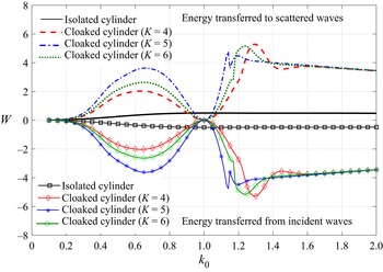
 $5$ and 6. We assume that the mass per unit area of rings is constant, and optimise for flexural rigidity (i.e. case II discussed in § 5). Energy conservation is expressed by (2.25), in which the first term is the part of incident wave energy that goes to scattered waves, and the second term is the energy of scattered waves (cf. (28) in Fàbregas Flavià & Meylan Reference Fàbregas Flavià and Meylan2019). These two energies are plotted in figure 8 where bottom curves (lines with symbols) show the energy transferred from the incident wave to scattered waves with a negative sign, and top curves (lines without symbols) show energy of scattered waves (note that curves of ‘energy transferred to scattered waves’ are the same as those plotted in figure 7(a), except that in figure 7(a) a log scale is used). Figure 8 shows that the two terms on the energy balance equation (2.25) have the same magnitudes (to graphical accuracy) with opposite signs and therefore add to zero. The exact accuracy of the energy balance here is, in fact, less than
 $O(10^{-14})$.
Energy balance against wave number  $k_0$. We consider case II (mass
 $\gamma ^{(k)}$ being constant across rings whereas
 $\gamma ^{(1)}$ can vary) with the radius of the plate
 $b=5.0$, and the number of rings
 $K=4$,
 $5$ and 6. Positive energies are energies transferred to scattered waves (i.e. energy of scattered waves) calculated by the second term in (2.25) whereas negative energies are energies transferred from incident waves calculated by the first term in (2.25). Total energy becomes zero with an accuracy of less than
 $O(10^{-14})$.