Introduction
A major challenge in developing effective biomedical technologies is the difficulty of shaping hydrogels, Reference Bhattacharjee, Zehnder, Rowe, Jain, Nixon, Sawyer and Angelini1–Reference Shim, Lee, Kim and Cho4 biopolymer networks, Reference Bertassoni, Cecconi, Manoharan, Nikkhah, Hjortnaes, Cristino, Barabaschi, Demarchi, Dokmeci and Yang5,Reference Kang, Lee, Ko, Kengla, Yoo and Atala6 silicones, Reference Bhattacharjee, Zehnder, Rowe, Jain, Nixon, Sawyer and Angelini1,Reference Hinton, Hudson, Pusch, Lee and Feinberg7–Reference O’Bryan, Bhattacharjee, Hart, Kabb, Schulze, Chilakala, Sumerlin, Sawyer and Angelini9 and cells Reference Bhattacharjee, Gil, Marshall, Urueña, O’Bryan, Carstens, Keselowsky, Palmer, Ghivizzani and Gibbs10–Reference Xu, Chai, Huang and Markwald12 into finely detailed three-dimensional (3D) structures. Generally, these soft materials must be shaped while in a liquid state before solidifying within seconds or minutes for biopolymer gelation, Reference Wood and Keech13–Reference Yang, Motte and Kaufman15 or within several days for cells producing the extracellular matrix. Reference Bhattacharjee, Gil, Marshall, Urueña, O’Bryan, Carstens, Keselowsky, Palmer, Ghivizzani and Gibbs10 The need to create high-resolution structures from these soft materials has driven 3D printing technology far beyond the traditional practice of liquefying, extruding, and resolidifying solid materials, entering a paradigm of shaping liquids in 3D space. The challenge of shaping liquids has led to a convergence among new printing technologies—they often leverage materials that exhibit large, reversible rheological changes resulting from small physical or chemical perturbations. This behavior is a defining characteristic of soft matter as a class of material. Reference de Gennes16 Beyond its typically low elastic modulus (usually below 10 MPa), this sensitivity of soft matter to small perturbations has been critical for developing new materials for bioprinting and for improving 3D printing of soft materials in general.
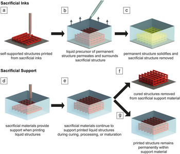
Until recently, it was practically impossible to reproducibly form soft materials into complex 3D structures at high spatial resolution; manufacturing processes resembled art more than manufacturing. Reference Bellan, Singh, Henderson, Porri, Craighead and Spector17 Manufacturing soft structures has been enabled by new methods and materials that leverage the unique properties of soft matter, which we review here. Significant progress has been made using “sacrificial” materials that are not ultimately part of manufactured structures, but leverage the highly responsive rheological properties of soft matter. We therefore limit the scope of this article to sacrificial inks and support materials. With sacrificial inks, a temporary structure is printed, surrounded by a permanent material, and then removed to create hollow structures ( Figure 1a–c). With sacrificial support materials, a permanent structure is printed directly into a sacrificial material that acts as a support matrix during the curing or maturation of the manufactured structure (Figure 1d–g).
Schematic representation of two broad approaches to 3D printing soft structures. For sacrificial inks, (a) structures are printed from self-supporting sacrificial materials and (b) immersed in a liquid precursor. (c) The surrounding permanent structure is solidified, and the sacrificial material is removed, resulting in a hollow 3D grid. For sacrificial support materials, (d) liquid inks are 3D printed directly into support materials. (e) The sacrificial material continues to provide support during the curing, processing, or maturation of the printed structure. Once cured, the sacrificial material can be either (f) removed from the printed structure or (g) left in place to provide permanent support to soft materials, including biological constructs.

Whenever possible, we identify the dominating rheological properties of these materials and discuss their consequences on manufacturing capabilities. We also describe the rheological concepts that allow differentiating and categorizing soft matter manufacturing materials. These basic concepts help predict the manufacturing capabilities of different soft materials by comparing stabilizing rheological properties and destabilizing external forces such as gravity, interfacial tension, and inertia. Thus, we identify scaling laws that relate the rheology of soft matter 3D printing materials to the potential instabilities associated with manufacturing processes and their resulting limitations.
Soft matter 3D printing principles
Rheological foundations
Recently developed sacrificial soft materials for 3D printing include jammed granular particles, Reference Bhattacharjee, Zehnder, Rowe, Jain, Nixon, Sawyer and Angelini1,Reference Hinton, Hudson, Pusch, Lee and Feinberg7,Reference O’Bryan, Bhattacharjee, Hart, Kabb, Schulze, Chilakala, Sumerlin, Sawyer and Angelini9,Reference Bhattacharjee, Gil, Marshall, Urueña, O’Bryan, Carstens, Keselowsky, Palmer, Ghivizzani and Gibbs10,Reference Jin, Compaan, Bhattacharjee and Huang18 entangled polymer solutions, Reference Hanson Shepherd, Parker, Shepherd, Gillette, Lewis and Nuzzo19 micelles packed into solid-like phases, Reference Homan, Kolesky, Skylar-Scott, Herrmann, Obuobi, Moisan and Lewis20,Reference Kolesky, Truby, Gladman, Busbee, Homan and Lewis21 and polymer networks with reversible bonds. Reference Highley, Rodell and Burdick22,Reference Rodell, Kaminski and Burdick23 These materials are designed or formulated to undergo large rheological changes that facilitate the printing process; some transition between solid and fluid states while others are better described as shear thinning fluids. Fundamental rheological concepts and simple models are useful tools for describing and categorizing these diverse materials, although such an in-depth discussion is outside the scope of this article. Thus, we have provided a “Supplementary material” section that describes basic rheological concepts and models and applies them to current soft matter 3D printing materials. There, we explain how concentrated micelles Reference Habas, Pavie, Lapp and Peyrelasse24,Reference Perreur, Habas, Peyrelasse, François and Lapp25 and polymer networks with weak reversible bonds Reference Highley, Rodell and Burdick22,Reference Rodell, Kaminski and Burdick23 often behave like liquids at long time scales, while jammed granular microgels behave dominantly like elastic solids. Reference Bhattacharjee, Zehnder, Rowe, Jain, Nixon, Sawyer and Angelini1,Reference O’Bryan, Bhattacharjee, Hart, Kabb, Schulze, Chilakala, Sumerlin, Sawyer and Angelini9,Reference Bhattacharjee, Gil, Marshall, Urueña, O’Bryan, Carstens, Keselowsky, Palmer, Ghivizzani and Gibbs10,Reference Dimitriou, Ewoldt and McKinley26,Reference LeBlanc, Niemi, Bennett, Harris, Schulze, Sawyer, Taylor and Angelini27 These diverging material properties control how different soft matter 3D printing materials yield during printing and hold their shape after printing, which we elaborate on next.
Feature size and material deposition rate
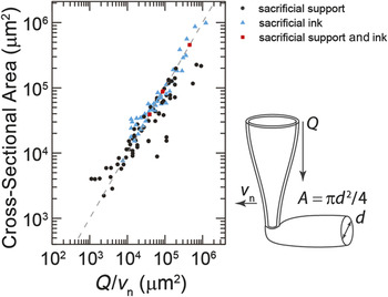
There are many standardized metrics of quality in additive manufacturing—accuracy is how closely a printed part matches its design; precision is the repeatability of a printing process; a feature is the discrete unit of positive or negative volume created in a printing process, such as a filament or a drop. 28 In surveying the soft matter printing literature, we use the cross-sectional area of single features as the standard for comparing different methods and materials. A key question of any soft matter printing method or material combination is whether the cross-sectional feature area, A, can be predicted using simple volume conservation from the material deposition rate, Q (dimensions of volume per time), and printing nozzle translation speed, v n , given by A = Q/v n. To answer this question, we identified publications in which A, Q, and v n were reported or could be inferred. This simple scaling law holds for more than three orders of magnitude in A and Q/v n, representing a general guideline for soft matter printing in practice ( Figure 2 ). Reference Bhattacharjee, Zehnder, Rowe, Jain, Nixon, Sawyer and Angelini1,Reference Ouyang, Highley, Rodell, Sun and Burdick3,Reference Shim, Lee, Kim and Cho4,Reference Xu, Chai, Huang and Markwald12,Reference Highley, Rodell and Burdick22,Reference LeBlanc, Niemi, Bennett, Harris, Schulze, Sawyer, Taylor and Angelini27,Reference Hinton, Jallerat, Palchesko, Park, Grodzicki, Shue, Ramadan, Hudson and Feinberg29–Reference Miller, Stevens, Yang, Baker, Nguyen, Cohen, Toro, Chen, Galie and Yu32 However, the spread in the data indicates that printing quality also depends on the details of each printing approach. For example, measurements of A can deviate from the volume conservation prediction if printed inks intermix with their support materials or if inks swell or contract following printing. Both scenarios may occur with soft matter printing approaches in which inks and support materials share the same solvent that can exchange between the two phases. It would be useful to investigate whether spontaneous phase separation assists in preventing inks and support materials from mixing.
The feature size of printed structures generally follows the scaling predicted from the material deposition rate (Q) and printing nozzle translation speed (v n) using volume conservation. Dashed line: A = Q/v n with no adjustable parameters. Data were collected from a survey of literature reporting on soft matter 3D printing methods and materials. Reference Bhattacharjee, Zehnder, Rowe, Jain, Nixon, Sawyer and Angelini1,Reference Ouyang, Highley, Rodell, Sun and Burdick3,Reference Shim, Lee, Kim and Cho4,Reference Xu, Chai, Huang and Markwald12,Reference Highley, Rodell and Burdick22,Reference LeBlanc, Niemi, Bennett, Harris, Schulze, Sawyer, Taylor and Angelini27,Reference Hinton, Jallerat, Palchesko, Park, Grodzicki, Shue, Ramadan, Hudson and Feinberg29–Reference Miller, Stevens, Yang, Baker, Nguyen, Cohen, Toro, Chen, Galie and Yu32

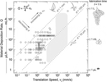
The direct correlation between measured and predicted feature size can be used to quantify the balance between total printed volume, nozzle translation speed, and feature size. Approximating the feature cross-sectional area as circular, the material deposition rate can be written as
 $Q = {{{\rm{\pi }}{d^2}} \over 4}{v_n}$
, where d is the feature diameter. Thus, any targeted feature diameter selects out a combination of material deposition rates and nozzle translation speeds that constitute a single manufacturing curve in Q–v
n space. We plot a family of such curves corresponding to feature diameters between 10 μm and 1000 μm, along with data collected from the published literature (
Figure 3
).
Reference Bhattacharjee, Zehnder, Rowe, Jain, Nixon, Sawyer and Angelini1,Reference Ouyang, Highley, Rodell, Sun and Burdick3,Reference Shim, Lee, Kim and Cho4,Reference Hinton, Hudson, Pusch, Lee and Feinberg7,Reference O’Bryan, Bhattacharjee, Hart, Kabb, Schulze, Chilakala, Sumerlin, Sawyer and Angelini9,Reference Xu, Chai, Huang and Markwald12,Reference LeBlanc, Niemi, Bennett, Harris, Schulze, Sawyer, Taylor and Angelini27,Reference Landers, Hübner, Schmelzeisen and Mülhaupt30–Reference Miller, Stevens, Yang, Baker, Nguyen, Cohen, Toro, Chen, Galie and Yu32,Reference Therriault, Shepherd, White and Lewis34,Reference Therriault, White and Lewis35
By applying a time constraint for printing an object of a given size, the speed–diameter tradeoff can be determined. For example, to print an object with 1 ml volume in 1 h, a 400 mm/s translation speed is required to achieve a feature diameter of 30 μm; at a modest speed of 35 mm/s, a feature diameter of only 100 μm is achievable. This problem becomes unmanageable for large volumes; printing a volume of 1 L with 100-μm features in 1 h requires translations speeds exceeding 30 m/s. By contrast, 100-μm features are easily achieved at print speeds of 10 mm/s, but the required time is about 150 days. The tradeoff between time, volume, feature size, and speed illustrates the conundrum faced in tissue and organ printing, where the goal is to manufacture large objects with small features over short times.
Reference LeBlanc, Niemi, Bennett, Harris, Schulze, Sawyer, Taylor and Angelini27,Reference Miller33
Q–v n manufacturing curves demonstrate the relationship between material deposition rate, Q, nozzle translation speed, v n and feature diameter, d (dashed lines). These curves can be used to determine the translation speeds required to achieve a desired feature diameter for a given material deposition rate. Manufacturing curves for feature diameters of 10 µm (width of a cell), 100 µm (width of a human hair), and 1 mm (width of a leaf stem) are shown. To print a grape-seed-sized structure within 1 h (Q = 1 μL/h) with a 10-μm feature size, a 4-mm/s translation speed is required. To print an object the size of a grape in 1 h (Q = 1 ml/h) at the same translation speed, the feature size will be 300 μm. To print a large object, for example, a structure the size of a cluster of grapes (Q = 1 L/h), a 300-μm feature size requires translation speeds in excess of 4 m/s. Open circles are data gathered from literature review. Reference Bhattacharjee, Zehnder, Rowe, Jain, Nixon, Sawyer and Angelini1,Reference Ouyang, Highley, Rodell, Sun and Burdick3,Reference Shim, Lee, Kim and Cho4,Reference Hinton, Hudson, Pusch, Lee and Feinberg7,Reference O’Bryan, Bhattacharjee, Hart, Kabb, Schulze, Chilakala, Sumerlin, Sawyer and Angelini9,Reference Xu, Chai, Huang and Markwald12,Reference LeBlanc, Niemi, Bennett, Harris, Schulze, Sawyer, Taylor and Angelini27,Reference Landers, Hübner, Schmelzeisen and Mülhaupt30–Reference Miller, Stevens, Yang, Baker, Nguyen, Cohen, Toro, Chen, Galie and Yu32,Reference Therriault, Shepherd, White and Lewis34,Reference Therriault, White and Lewis35 The gray region represents manufacturing space that is currently achievable.

Instabilities: Competition between soft matter rheology and confounding forces
Inertial forces and Reynold’s instabilities
An obvious approach for achieving fine features in manufacturing large objects over short times is to rapidly translate printing nozzles. However, inertial instabilities may arise at high speeds, generating unpredictable flows that reduce printing quality (
Figure 4a). Instabilities controlled by competing viscous and inertial forces can be predicted by estimating the Reynold’s number. For a cylindrical nozzle of diameter d, dragging through a fluid with density ρ and viscosity η at speed v, the Reynold’s number is given by
 $Re = {\rm{\rho }}vd{\rm{/\eta }}$
. For flow around a needle translating through a support material, recirculation in the wake emerges at around Re = 10–15,36–38 setting an upper bound on the speeds and needle sizes suitable for quality printing. High-speed printing within a sacrificial microgel support was performed at v = 1.05 m/s, where recirculating instabilities emerged at Re between 3.7 and 17, consistent with unstable flow around a cylinder.
Reference LeBlanc, Niemi, Bennett, Harris, Schulze, Sawyer, Taylor and Angelini27,Reference Thom38
In these tests, the ink viscosity controlled the Reynold’s number at the needle tip.
Reference LeBlanc, Niemi, Bennett, Harris, Schulze, Sawyer, Taylor and Angelini27
As high-speed printing methods emerge, a combination of small needle diameters and high fluid viscosities will help avoid inertial instabilities, increasing print quality.
Instabilities encountered in soft matter printing. (a) Inertial instabilities arise when printing low viscosity inks at high nozzle translational speeds, v n, producing recirculation in the wake of the nozzle and intermixing of the support material and printed ink. Transient crevasses can arise in the wake of the nozzle at high speeds. (b) Static crevasse formation occurs in the wake of the printing nozzle when the yield stress of the support material exceeds the hydrostatic pressure. (c) Gravitational forces can cause material sag when printed structures are not supported by a sacrificial material. (d) Interfacial tension between support materials and inks break up printed structures smaller than a critical size, l c. Note: Re, Reynold’s number; L, depth of the printing nozzle; ρ, density; σy, yield stress, η, Newtonian viscosity; γ, interfacial tension; d, feature diameter; l, printed feature diameter; g, acceleration due to gravity.

Dynamic and static crevasse formation
When printing at high speeds, the reflow of support material in the nozzle’s wake may be slow, opening a transient crevasse that follows behind the printing nozzle (Figure 4a). This transient crevasse instability arises from the competition between the hydrostatic pressure that drives fluid reflow, ρgh, and the viscous stresses resisting reflow, vη/d. In this dynamic equilibrium, v is both the reflow speed and nozzle translation speed, d is the nozzle diameter and gap width, h is the crevasse depth, ρ and η are the density and viscosity of the support medium, respectively, and g is the acceleration due to gravity. These transient crevasses were reported for printing into a microgel support material, Reference LeBlanc, Niemi, Bennett, Harris, Schulze, Sawyer, Taylor and Angelini27 though in principle, they can arise with most soft matter support materials. These transient near-surface crevasses are unlikely to reduce printing quality until the crevasse grows to meet the nozzle tip and material deposition occurs at the air–support interface. Therefore, v should be kept below ρgLd/η, in which L is the submerged depth of the printing nozzle. An alternative to limiting v is to increase L with a longer needle, although the resulting increased needle deflection will reduce printing accuracy.
Even in the limit of zero nozzle translation speed, crevasses can emerge (Figure 4b). These static crevasses are produced when the hydrostatic pressure at a depth, h, is less than the yield stress of the support material, described by ρgh ≤ σy. In many viscous liquids and materials with low yield stresses, these static crevasses do not arise. Reference Bhattacharjee, Zehnder, Rowe, Jain, Nixon, Sawyer and Angelini1,Reference Hinton, Hudson, Pusch, Lee and Feinberg7,Reference O’Bryan, Bhattacharjee, Hart, Kabb, Schulze, Chilakala, Sumerlin, Sawyer and Angelini9,Reference Bhattacharjee, Gil, Marshall, Urueña, O’Bryan, Carstens, Keselowsky, Palmer, Ghivizzani and Gibbs10,Reference Highley, Rodell and Burdick22,Reference LeBlanc, Niemi, Bennett, Harris, Schulze, Sawyer, Taylor and Angelini27,Reference Hinton, Jallerat, Palchesko, Park, Grodzicki, Shue, Ramadan, Hudson and Feinberg29 When they do emerge, crevasses can be filled with a secondary support liquid that continuously flows into the gap. Reference Wu, DeConinck and Lewis39
Gravitational instabilities
Gravity often causes printed structures to sag; a traditional method for overcoming sag is to simultaneously print sacrificial support structures and permanent structures (Figure 4c). Reference Lee, Hong, Jung, Shim, Oh and Cho2,Reference Kang, Lee, Ko, Kengla, Yoo and Atala6,Reference Pati, Shim, Lee and Cho11,Reference Compaan, Christensen and Huang40,Reference Visser, Peters, Burger, Boomstra, Dhert, Melchels and Malda41 The support must solidify rapidly after printing and wash away gently without damaging the permanent structure. This process was demonstrated with support materials, including poly(ethylene) glycol (PEG), poly(ε-caprolactone) (PCL), and alginate. Reference Lee, Hong, Jung, Shim, Oh and Cho2,Reference Pati, Shim, Lee and Cho11,Reference Visser, Peters, Burger, Boomstra, Dhert, Melchels and Malda41 Sacrificial inks that become rigid have also been developed; preprinted sacrificial structures can be submerged into a liquid precursor of a permanent material that is cured. The sacrificial ink is then removed, leaving channels that can be lined with living cells, for example. Reference Kolesky, Truby, Gladman, Busbee, Homan and Lewis21,Reference Miller, Stevens, Yang, Baker, Nguyen, Cohen, Toro, Chen, Galie and Yu32,Reference Therriault, Shepherd, White and Lewis34,Reference Therriault, White and Lewis35,Reference Kolesky, Homan, Skylar-Scott and Lewis42–Reference Zhao, Lee, Yoo, Dai and Intes46
Gravitational instabilities can also be overcome by 3D printing directly into a sacrificial support material, reducing buoyancy forces by matching the densities of inks with sacrificial liquid baths.
Reference Xu, Chai, Huang and Markwald12,Reference Landers, Hübner, Schmelzeisen and Mülhaupt30,Reference Landers, Pfister, Hübner, John, Schmelzeisen and Mülhaupt31
Density matching requirements can be estimated by equating the destabilizing buoyancy force of a 3D printed sphere to the resisting Stoke’s drag, given by
 $\Delta {\rm{\rho }}Vg = 6{\rm{\pi \eta }}rv$
, where Δρ is the density mismatch, V is the sphere volume, g is the acceleration due to gravity, η is the support liquid viscosity, r is the sphere radius, and v is the speed at which the sphere rises or sinks.
Reference Stokes47
To prevent a d = 1 mm sphere from rising in 1 h by its own diameter through an aqueous solution (η ≈ 1 mPa s), the printed structure must have a density within 4.5 × 10⁻⁴% of water. Thus, even using viscous support materials, alternatives to density matching may better reduce the role of buoyancy forces in soft matter printing.
An alternative to density matching is to print directly into sacrificial support materials having a finite yield stress at long time scales, such as jammed granular materials and polymer networks.
Reference Bhattacharjee, Zehnder, Rowe, Jain, Nixon, Sawyer and Angelini1,Reference Hinton, Hudson, Pusch, Lee and Feinberg7,Reference O’Bryan, Bhattacharjee, Hart, Kabb, Schulze, Chilakala, Sumerlin, Sawyer and Angelini9,Reference Bhattacharjee, Gil, Marshall, Urueña, O’Bryan, Carstens, Keselowsky, Palmer, Ghivizzani and Gibbs10,Reference Highley, Rodell and Burdick22,Reference LeBlanc, Niemi, Bennett, Harris, Schulze, Sawyer, Taylor and Angelini27,Reference Hinton, Jallerat, Palchesko, Park, Grodzicki, Shue, Ramadan, Hudson and Feinberg29,Reference Wu, DeConinck and Lewis39
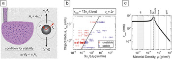
This approach provides gravitational stability with dramatically reduced limitations on material density. The stability of an object supported by a material with yield stress, σy, can be predicted by comparing the gravitational force to the yielding force, given by ΔρVg < σy
A
h, where Δρ is the difference between printed and support material densities, V is the printed object’s volume, g is acceleration due to gravity, and A
h is the hydrodynamic surface area (
Figure 5a). For 3D printing spheroids, this stability condition predicts a maximum radius for stability,
 ${r_c} = {{\rm{\beta }}^2}{{\rm{\sigma }}_y}{\rm{/}}\Delta {\rm{\rho }}g$
, where β is the hydrodynamic radius scaling coefficient given by r
h = βr (Figure 5b). For a soft matter printing support material of known yield stress, a chart can be generated to estimate the size limits on stable printing with inks of different densities (Figure 5c). A support material will stabilize a larger object made from, for example, low-density fatty tissue than from higher-density bony material.
Stability of printed structures inside sacrificial support materials. (a) A structure does not rise or sink if the gravitational force is less than the force required to yield the support material. (b) A stability diagram shows the size cutoff for spherical objects supported by a sacrificial support. Commonly available materials and sizes were estimated to be stable or unstable if supported by jammed microgel materials from the literature (materials: gold, copper, stainless steel, aluminum, glass, tungsten carbide, silicon nitride, polyurethane, neoprene rubber, and natural gum rubber; radii between 0.4 mm and 12.7 mm; yield stresses between 1 Pa and 9 Pa). In the authors’ experience, this stability analysis holds if r h = 2r. (c) For a support material with a given yield stress, the largest object that can be supported and remain stable can be predicted by the material density. The case of a 10 Pa yield stress is depicted here. Note: r, sphere radius; r h, hydrodynamic radius; A h, hydrodynamic area; σy, yield stress; Δρ, difference in density; V, volume; g, acceleration due to gravity; r max, maximum radius for stability.

Interfacial forces and the Rayleigh–Plateau instability
Immiscibility between support materials and printed inks provides a diffusive barrier, prevents their mixture, and promotes smooth surfaces with consistent cross-sectional areas. However, these interfacial forces can destabilize structures through a mechanism similar to the Rayleigh–Plateau instability (Figure 4d). The balance between destabilizing interfacial forces and stabilizing yield stress creates a minimum stable feature size, l
c, given by
 ${l_c} = {\rm{\gamma /}}{{\rm{\sigma }}_y}$
, where γ is the interfacial tension between the support material and ink, and σy is the support material’s yield stress.
Reference Pairam, Le and Fernández-Nieves48–Reference Style, Jagota, Hui and Dufresne51
Instabilities arising from interfacial forces are overcome when printing large features into materials with large yield stresses.
Reference Hinton, Hudson, Pusch, Lee and Feinberg7
An additional concern when printing with immiscible pairs is the accumulation of nanoparticles or microparticles at the ink–support interface. Reference Chang, Fragkopoulos, Marquez, Kim, Angelini and Fernández-Nieves52 Similar to Pickering emulsions, in which micro- or nanoparticles stabilize droplets and prevent coalescence by accumulating at the droplet surface, filler material in the printed ink will accumulate at the interfaces between printed features and immiscible support material. Reference Binks53,Reference Pickering54 This Pickering effect can reduce adhesion between printed filaments. Reference Hinton, Hudson, Pusch, Lee and Feinberg7 One potential solution is to develop new support materials that remain immiscible with inks, but exhibit a drastically reduced interfacial tension. Reference O’Bryan, Bhattacharjee, Hart, Kabb, Schulze, Chilakala, Sumerlin, Sawyer and Angelini9
Thixotropic instabilities: A new opportunity in soft matter 3D printing
A characteristic of most sacrificial support materials is the tendency to rapidly recover zero-shear rate rheological properties after yielding or shear thinning (see the “Supplementary material” section). This recovery upon the removal of stress arises from differing underlying processes in different materials, yet is broadly called thixotropy; the corresponding time scale is the “thixotropic time.” When 3D printing into sacrificial support materials, returning to the same location before thixotropic relaxation has occurred may reduce printing quality. Thixotropy in sacrificial support materials were reported and commented on previously, Reference Bhattacharjee, Zehnder, Rowe, Jain, Nixon, Sawyer and Angelini1,Reference O’Bryan, Bhattacharjee, Hart, Kabb, Schulze, Chilakala, Sumerlin, Sawyer and Angelini9,Reference Highley, Rodell and Burdick22 however, additive manufacturing path-planning principles that leverage this rheological property have not been developed. We envision new nozzle path-planning protocols that prohibit revisiting locations until the thixotropic time has elapsed, ensuring that the support material is always in the same rheological state, locally, when printing.
Conclusion and outlook
One goal has dominantly motivated the invention of new materials and methods in soft matter manufacturing—to 3D print functional tissues and organs for implantation. The manufacturing charts produced here corroborate the current view that soft matter printing technology is still far from reaching this goal, Reference Miller33 which may be achieved more quickly by establishing manufacturing principles that help to predict the performance of new materials and methods. In the immediate term, current levels of manufacturing speed, precision, accuracy, and rheological stability provided by soft matter 3D printing methods and materials are sufficient to make significant impacts in mesoscale biomanufacturing applications. For example, microscale to millimeter-scale structures made from living cells and extracellular matrix materials can now be 3D printed rapidly and reproducibly. Reference Bhattacharjee, Gil, Marshall, Urueña, O’Bryan, Carstens, Keselowsky, Palmer, Ghivizzani and Gibbs10,Reference Kolesky, Truby, Gladman, Busbee, Homan and Lewis21 These structures can be used to discover new drugs, screen for compound toxicity, and study new therapeutic approaches before conducting animal or patient trials. Moreover, these approaches can be used to perform basic research on cell behavior in 3D printed microtissues, which is needed to elucidate the principles that will one day enable large-scale tissue and organ fabrication.
Acknowledgment
This work was funded by the National Science Foundation under Grant DMR-1352043.

Christopher S. O’Bryan is a doctoral candidate in the Department of Mechanical and Aerospace Engineering at the University of Florida. He received his BS degree in aerospace engineering from the University of Florida in 2012. His research is focused on soft matter engineering; working on developing new methods in soft matter manufacturing, and investigating cell mechanics in the 3D environment. O’Bryan can be reached by phone at 352-392-4442 or by email at csobryan@ufl.edu.

Tapomoy Bhattacharjee is a doctoral candidate in the Department of Mechanical and Aerospace Engineering at the University of Florida. He received his BS degree in chemical engineering from Jadavpur University, India, in 2012, and his MS degree in chemical engineering and MS degree in mechanical engineering from the University of Florida in 2014 and 2015, respectively. His research is focused on exploring jamming in microgels; manufacturing soft structures of cells, colloids, and polymers inside jammed granular microgel media; and investigating cell dynamics in a 3D microgel medium. Bhattacharjee can be reached by phone at 352-392-4442 or by email at tapomoy@ufl.edu.

Sean R. Niemi is a doctoral candidate in the Department of Mechanical and Aerospace Engineering at the University of Florida. He received his BS degree in mechanical engineering and BS degree in aerospace engineering from the University of Florida in 2012, followed by his MS degree in mechanical engineering in 2015. His research is focused on soft matter manufacturing and developing new methods and technologies to allow for higher speed biomanufacturing. Niemi can be reached by phone at 352-846-0151 or by email at impstar@ufl.edu.

Sidhika Balachandar is a junior at Buchholz High School in Gainesville, Fla. She participated in research at the University of Florida as part of her science fair project in 2015. She has successfully participated in science fairs at the national and international level and is an active member of her high school’s Mu Alpha Theta math team. Balachandar can be reached by phone at 352-331-5408 or by email at sbalachandar@gm.sbac.edu.

Nicholas Baldwin is an undergraduate student studying mechanical engineering at the University of Florida. He participated in research at the University of Florida as part of his high school’s Student Science Training Program. Baldwin can be reached by phone at 561-676-0817 or by email at Nlbaldwin98@ufl.edu.

S. Tori Ellison is a graduate student in the Department of Mechanical and Aerospace Engineering at the University of Florida. She received her BS degree in materials science and engineering from the University of Florida in 2016. Her research is focused on soft matter engineering investigating cell mechanics in the 3D environment using jammed microgels. Ellison can be reached by phone at 352-392-4442 or by email at trilison@ufl.edu.

Curtis R. Taylor has been an associate professor in the Department of Mechanical and Aerospace Engineering at the University of Florida since 2008. He received his MS (2002) and PhD (2005) degrees in electrical engineering and physics from the University of Arkansas. His research interests include mechanical behavior of materials, nanomaterials, and advanced manufacturing. He is a member of the American Society of Mechanical Engineers and the Materials Research Society. Taylor can be reached by phone at 352-392-4440 or by email at curtis.taylor@ufl.edu.

W. Gregory Sawyer is a Distinguished Teaching Scholar and the N.C. Ebaugh Professor of Mechanical and Aerospace Engineering at the University of Florida. He received his PhD degree in mechanical engineering in 1999 from Rensselaer Polytechnic Institute with a focus on tribology. His research interests include remote testing on the International Space Station and in vivo friction measurements on a cornea. His current research focuses on developing manufacturing technologies for tissue engineering. Sawyer can be reached by phone at 352-392-8488 or by email at wgsawyer@ad.ufl.edu.

Thomas E. Angelini is an associate professor in the Department of Mechanical and Aerospace Engineering at the University of Florida. He received his PhD degree in physics from the University of Illinois in 2005. He joined the faculty at the University of Florida in 2010, and received an NSF CAREER Award in 2014 to study the stability and dynamics of multicellular assemblies in yield stress materials. His research interests include collective cell behavior, soft matter physics, and soft matter manufacturing. Angelini can be reached by phone at 352-392-6438 or by email at t.e.angelini@ufl.edu.