Introduction
Nowadays, wide-band wireless telecommunication is growing in new generation of broad-band wireless technology antenna designs [Reference Naser-Moghaddasi1–Reference Naser-Moghaddasi3]. Broad-band engineering necessitates electrically small-size antennas for wireless hand-held devices. The printable circular polarization (CP)-antenna illustrates very absorbing attention for designing broad-band systems because of easy realization, miniaturized dimensions, omni-directional far-filed patterns over the applicational band, and obtaining CP in operational bands [Reference Naser-Moghadasi and Sedgeechongaraluye-Yekan4–Reference Cai6]. Semi-fractal structures are designed on self-similarity and space-filling properties. They can be used to improve the antenna performance for instance, impedance matching bandwidth (BW), tuning attributes, and radiation characteristics [Reference Hsieh7, Reference Sedgeechongaraluye-Yekan, Sadeghzadeh and Naser-Moghadas8]. There are multiple narrow sub-bands that might interfere with wide-band wireless systems, such as ITU-R and IEEE802.11a (wireless local area network 5.15–5.825 GHz), thus the antenna with band-stopped specifications is required. Different designs in wide-band antenna with band-stopped operation have been presented in previously published scholars. Those schemes use different kinds of stubs, slots, and semi-parasitic elements in the ground surface and the patch, or even in the feed-line to achieve the band-stopped implementation with minimum consequence in pass band [Reference Naser-Moghaddasi1–Reference Sedgeechongaraluye-Yekan, Sadeghzadeh and Naser-Moghadas8]. Previous techniques have undesirable intrinsic specifications, for example, narrow BW, incapable radiation specs, deducing from antenna's small size at operating frequency [Reference Sedgeechongaralouye-Yekan, Naser-Moghadasi and Sadeghzadeh9]. CP can prevail matters related with multipath fading to increase system capacity. Besides that, it can enable much better weather penetration and mobility than linearly polarized systems [Reference Sedgeechongaraluye-Yekan, Naser-Moghadasi and Sadeghzadeh10–Reference Farswan12]. CP provides continuous wireless communications, while the orientations of the transmitter and receiver antennas are not important. None of the previously reported designs have such properties, but in proposed antennas along with dual-band rejection, CP is achieved with semi-fractal geometry, stubs, and slots structures. In this paper, a special form of coplanar waveguide (CPW)-fed CP-antenna with unit-cell patterns of mirrored semi-fractal (UPMSF) radiator and rectangular-shaped mirrored defected ground structure (MDGS) is proposed to defeat some of the intrinsic property of square slot antenna. With semi-fractal geometry and square slot scheme, coupling of power from transmission lines and radiator to free space in much smaller volume and background power reflection is achieved. Also, with this outstanding design, CP is introduced easily and two equal orthogonal modes are stimulated in IEEE802.16 band. This phenomenon has major value for a broad-band dual-band-notched CP antenna in new generation of wireless communication. The distinguished features of the proposed UPMSF antenna are the compact size, band-stopped characteristics, and CP features that are achieved without impressing other radiation performances. The first band-stopped performance (5–6 GHz WLAN) and CP property is achieved by semi-fractal geometry and mirrored U-shaped unit-cell patterns embedded on the UPMSF patch. The second band notch is achieved from embedding rectangular-shaped MGDS at both sides of CPW ground. These combinational methods lead to orthogonal modes generation for archiving CP in WiMAX. The antenna laboratory measured results illustrate that the proposed CP-antenna functions over the frequencies of 2.9–12.61 GHz for S 11 < −10 dB, except two filtering bands (5.02–5.9 GHz and 7.2–8.7 GHz), aimed at canceling any interference from WLAN IEEE802.11a (5.15–5.825 GHz) and ITU-R BW. In addition, the antenna has useful CP properties in WiMAX IEEE802.16 (3.3–3.6 GHz), C-band (3.7–4.2 GHz), based on the novel proposed scheme of UPMSF design and MDGS geometry. The square slot CP-antenna has an efficient far-field patterns and gain. It operates outstandingly with its specific characteristics for ultra-wide-band (UWB) frequency range. Simulated and measured results of the fabricated CP-antenna with the different layouts of UPMSF radiator and ground structures are presented.
Antenna design
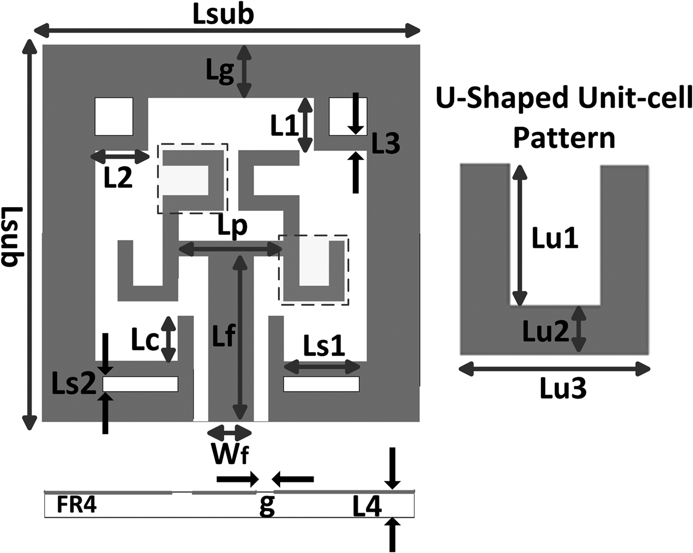
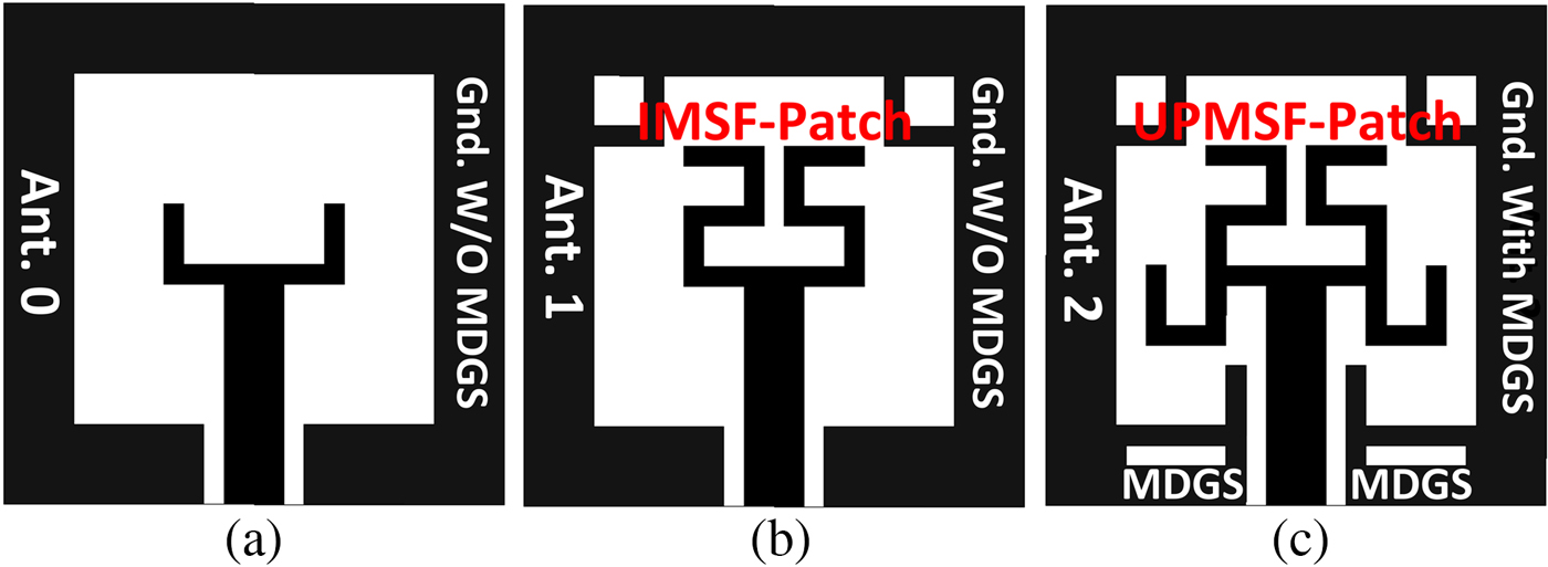
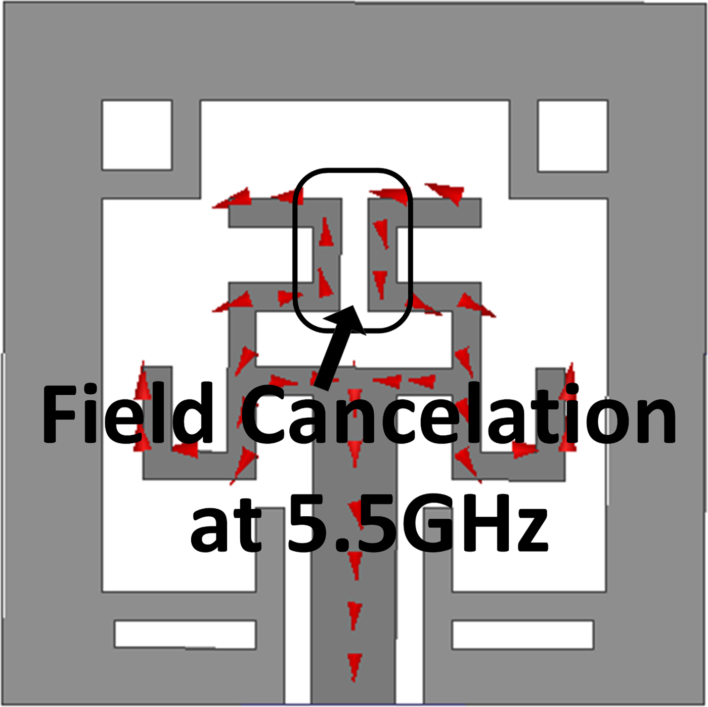
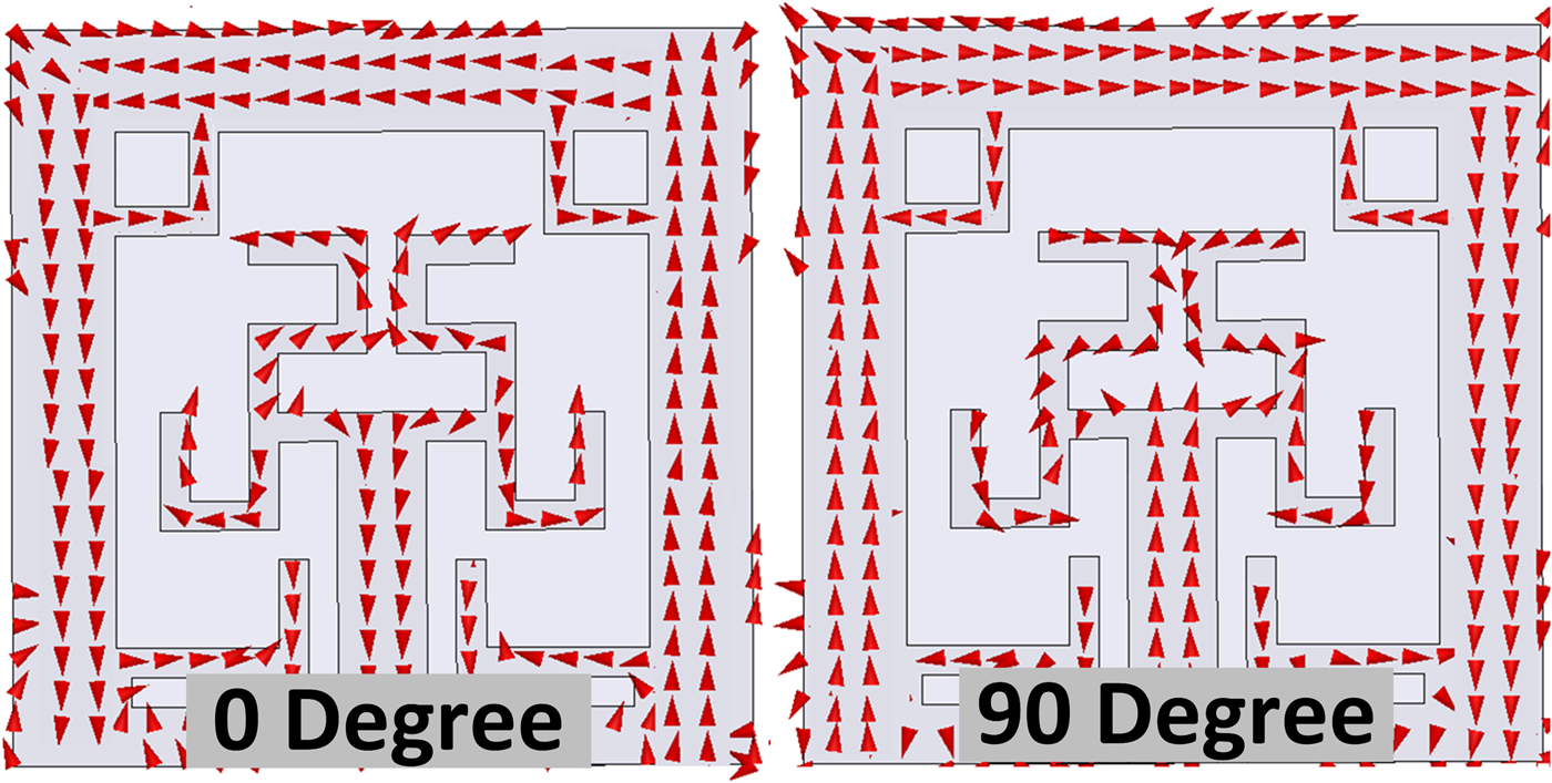
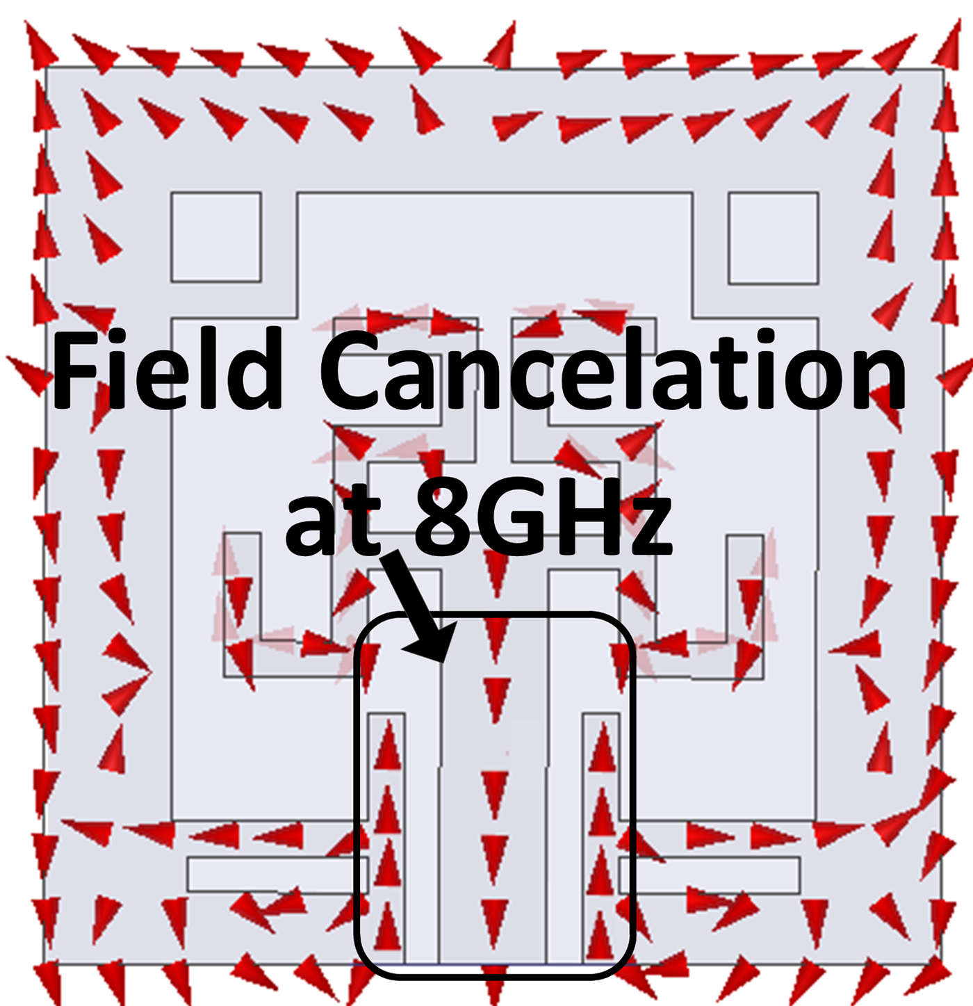
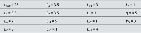
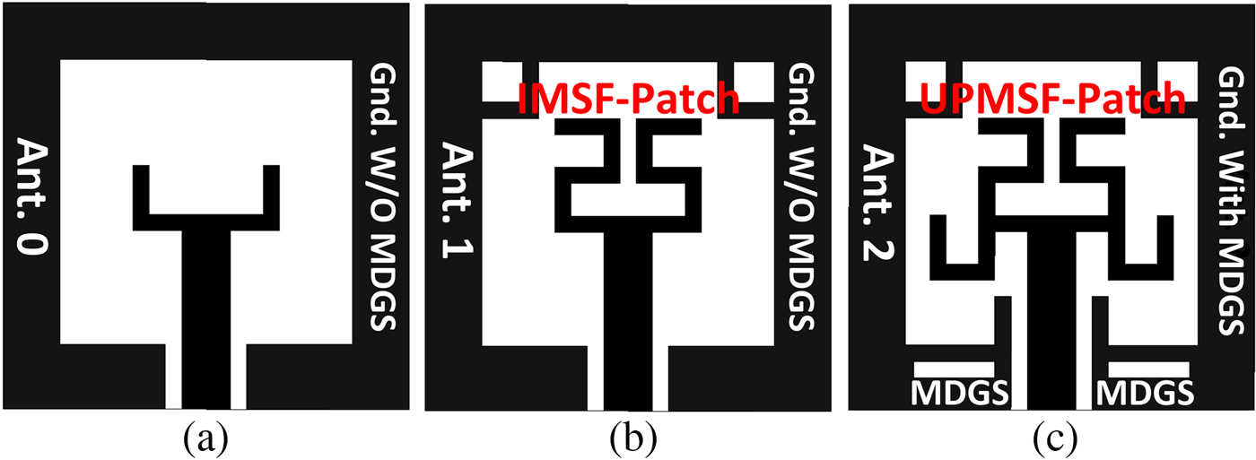
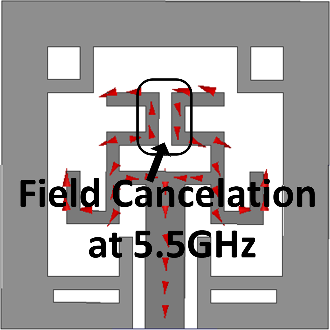
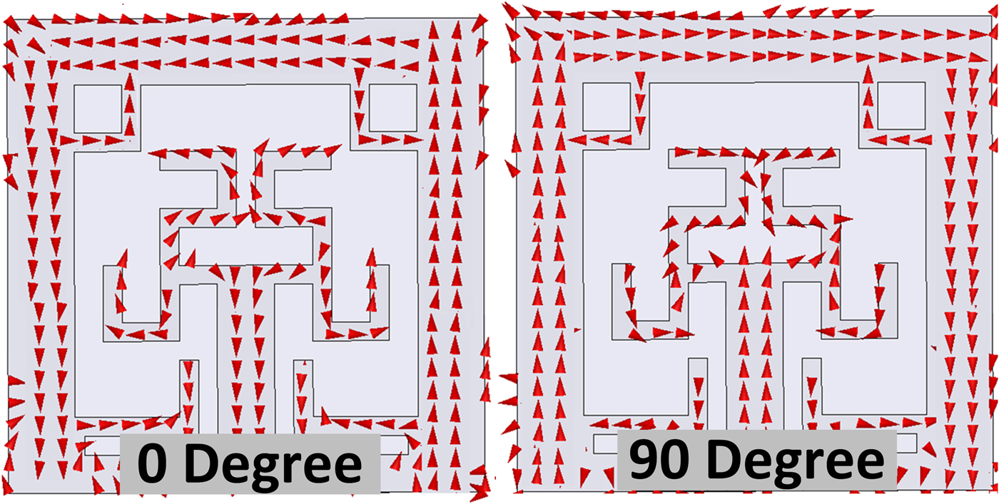
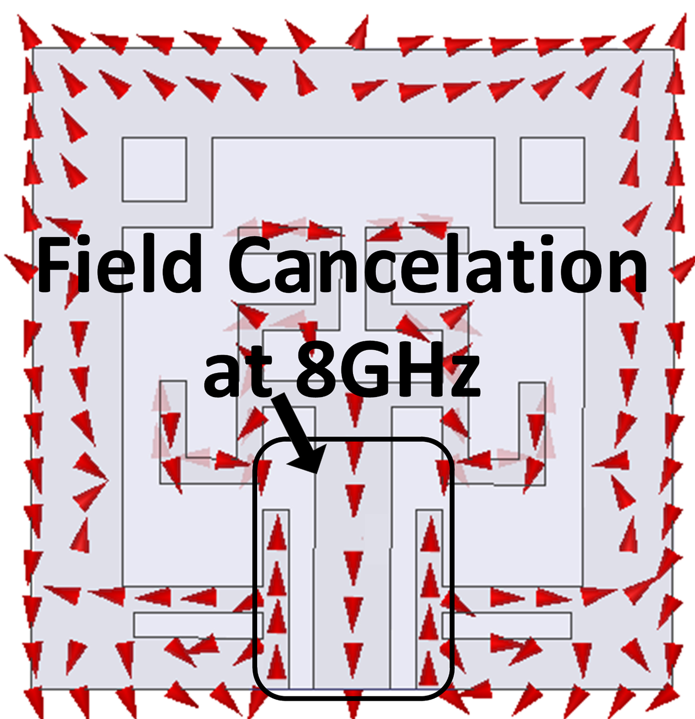
The semi-fractal dual-band-notch CP-antenna configuration with 25 mm × 25 mm dimensions is depicted in Fig. 1. The proposed compact antenna is fabricated on FR4-epoxy substrate with 1 mm thickness, tanδ = 0.02 and ε r = 4.4. CPW technology is used to feed the CP-antenna unit-cell-based semi-fractal radiator with specific form of patterns. The radiator element is made of two semi-fractal branches that each one has limited number of U-shaped unit-cell patterns, which form a UPMSF conformation. The CPW feed-line optimum width (W f) is set to 3 mm for 50 Ω characteristic impedance. A pair of 1 mm × 5 mm rectangular-shaped slits is cut from CPW ground surface to complete ground circuit. The gap is set as 0.5 mm between the CPW feed-line and ground surface for efficient impedance tuning. The gap among UPMSF radiator and the CPW ground surface is specified with distance (L f–L c), for the relatively impressive impedance matching. The parametric study of gap sets the optimum value for 2 mm. The proposed procedure of CP-antenna layout is shown in Fig. 2. To modify the capability of the CP-antenna from UWB attribute to the first band filtering, a special and exquisite scheme of initial step of semi-fractal U-shaped unit cell is introduced. WLAN (5.15–5.825 GHz) is rejected in the frequency band of CP-antenna by embedding UPMSF (see Fig. 3). Figure 3 shows field cancelation of current distribution at 5.5 GHz for first band filtering. Furthermore, because of L-shaped strips and semi-fractal structure existence, surface current distribution of radiator and ground modifies and results to generate CP in WiMAX (see Fig. 4). The simulation results of surface current distribution for final antenna are depicted in Fig. 4 at 3.5 GHz in the phases of 0o and 90o. It is observed that grounded L-shaped strips have major role in the surface current distribution. If the current rotates in the clock wise and counter clockwise directions, the antenna can radiate the right-hand circular polarization (RHCP) and the left-hand circular polarization (LHCP), respectively. Utilizing defected ground surface technique that consists of two mirrored rectangular-shaped slots from CPW ground planes, the second filtering band (ITU-R) is achieved. Two U-shaped unit-cell strips are employed on the initial semi-fractal patch to get the first stopped band centered at 5.5 GHz, whereas the grounded L-shaped stubs is attached for controlling the current distribution on CPW at ground surface. Besides that, a pair of rectangular-shaped MDGS is applied to final antenna (Ant. 2) to achieve the second filtered band centered at 8 GHz. Figure 5 shows field cancelation of current distribution at 8 GHz for second band filtering. The process of UPMSF and MGDS modification steps (Ant. 1 and Ant. 2) is studied in Fig. 2. The UPMSF and initial mirrored semi-fractal (IMSF) radiators layout is designed to obtain sufficient impedance matching in Ant. 1 and Ant. 2 at upper frequencies. The process of IMSF, UPMSF, and MGDS strategy in semi-fractal CP-antenna is summarized as follows (see Fig. 2):
(I) A simple square slot antenna with fork-shaped feed-line is introduced to form Ant. 0.
(II) One pair of U-shaped unit-cell patterns (IMSF patch) with a pair of grounded strips are applied to Ant. 0 to form Ant. 1.
(III) Another pair of U-shaped unit-cell patterns is attached to the previous step to generate final semi-fractal radiator (UPMSF) and a pair of rectangular-shaped mirrored defected ground structure is cut from the ground surface of Ant. 1 to present ultimate antenna (Ant. 2). The dimensions of fabricated CP-antenna in Fig. 1 are listed in Table 1 (units: mm).
Fig. 1.Ultimate CP-antenna configuration with the proposed scheme of UPMSF, MGDS, and unit-cell pattern.
 Fig. 2.
CP-antenna design process (a) Ant. 0 with initial U-shaped radiator, (b) Ant. 1 with a pair of grounded L-shaped strips and initial mirrored semi-fractal (IMSF) patch, (c) Ant. 3 with ultimate unit-cell pattern of mirrored semi-fractal (UPMSF) patch, and mirrored defected grounded structure (MDGS).
Fig. 3.Field cancelation of current distribution at 5.5 GHz for first band filtering.
Fig. 4.Distribution of the surface current on the feed and ground of the structure at 3.5 GHz in 0o and 90o phases.
Fig. 5.Field cancelation of current distribution at 8 GHz for the second band filtering.
Table 1.Dimensions of the antenna


Simulation and measurement result
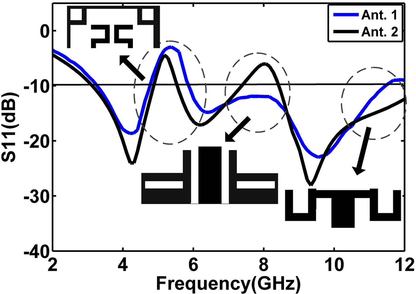
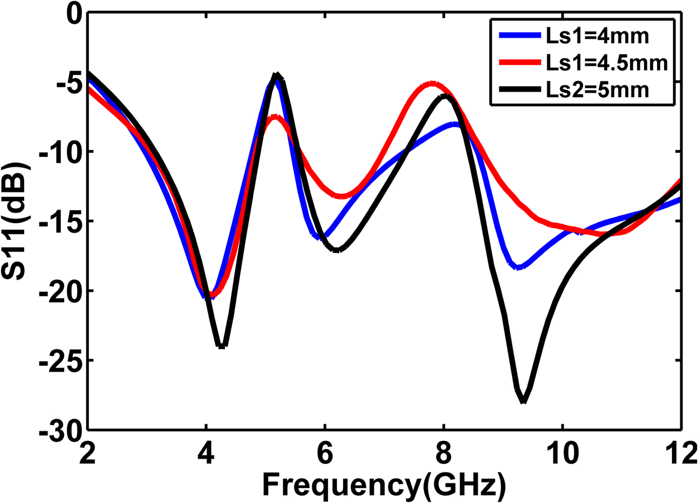
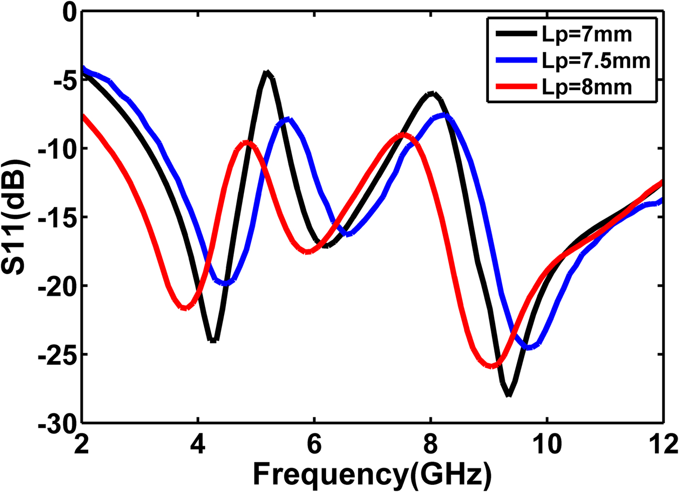
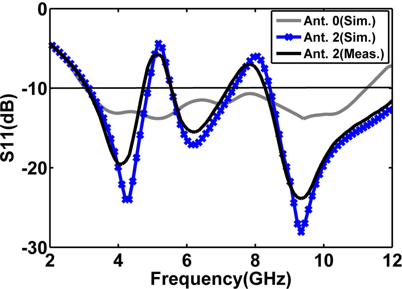
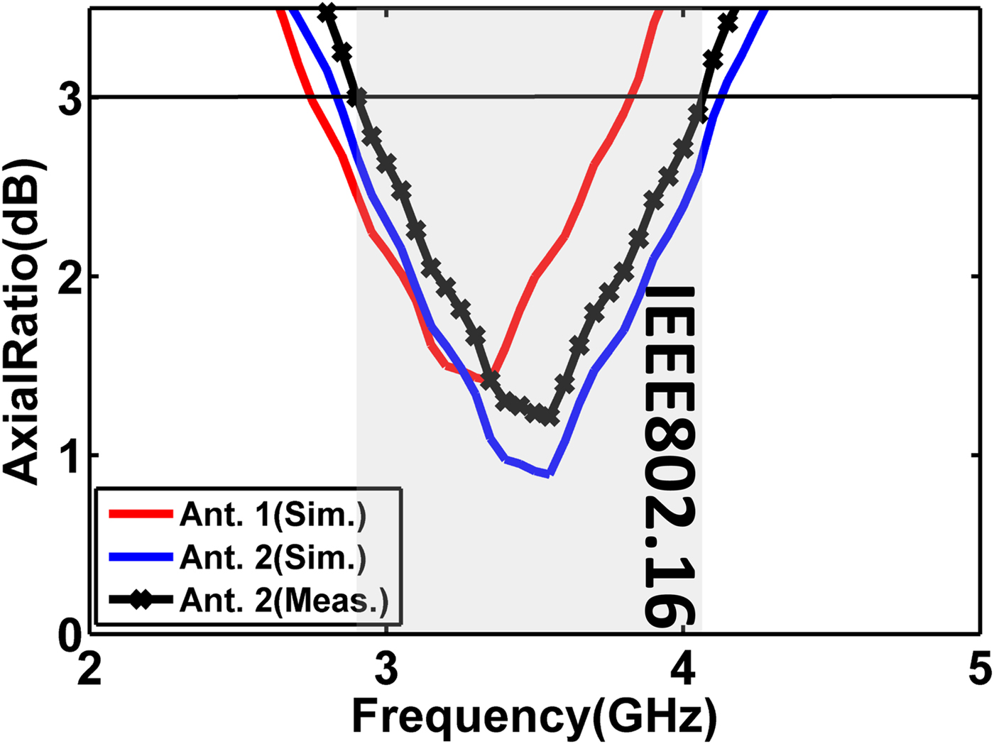
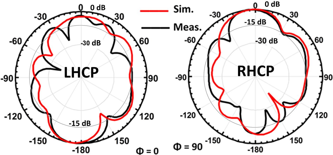
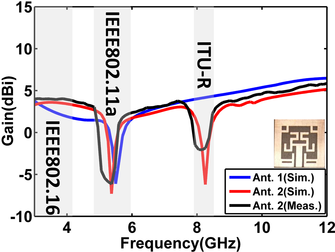
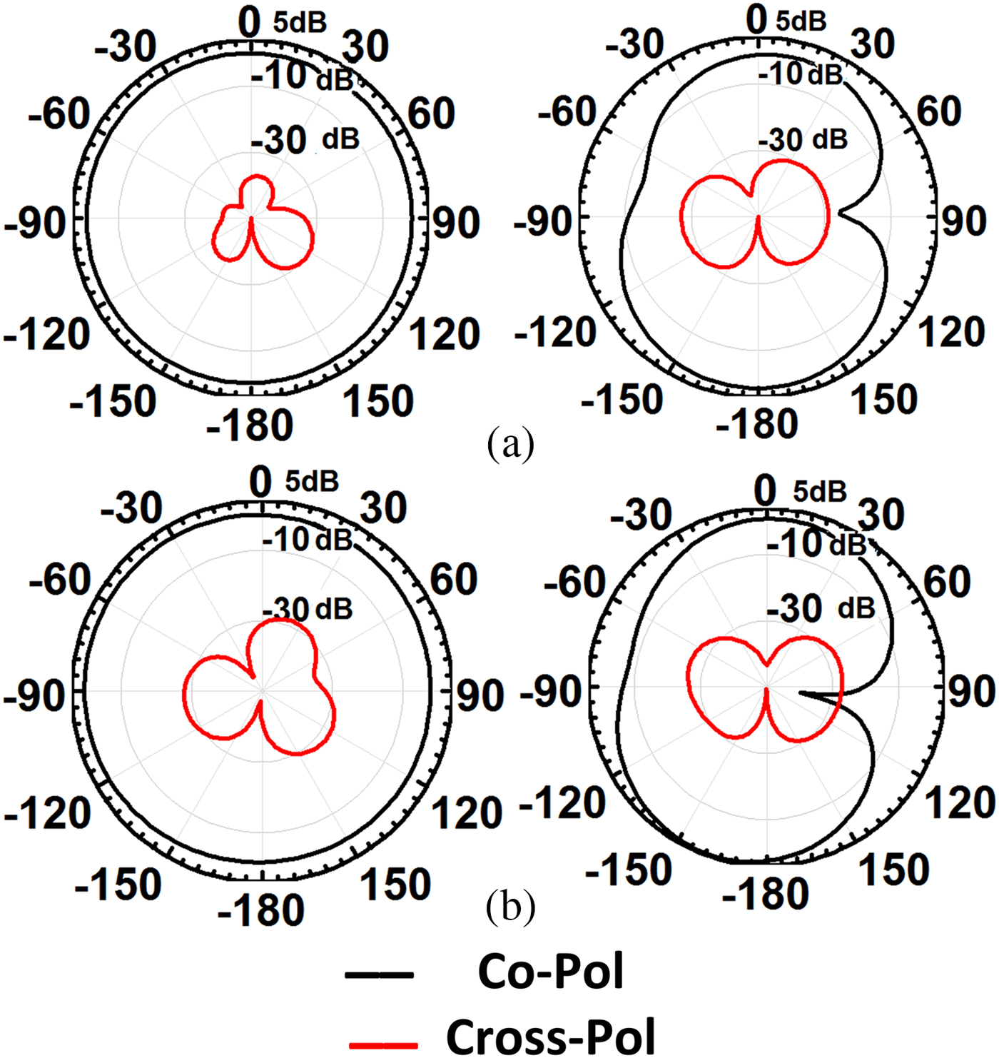
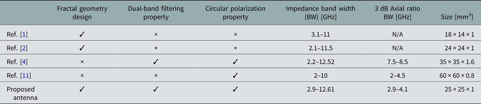
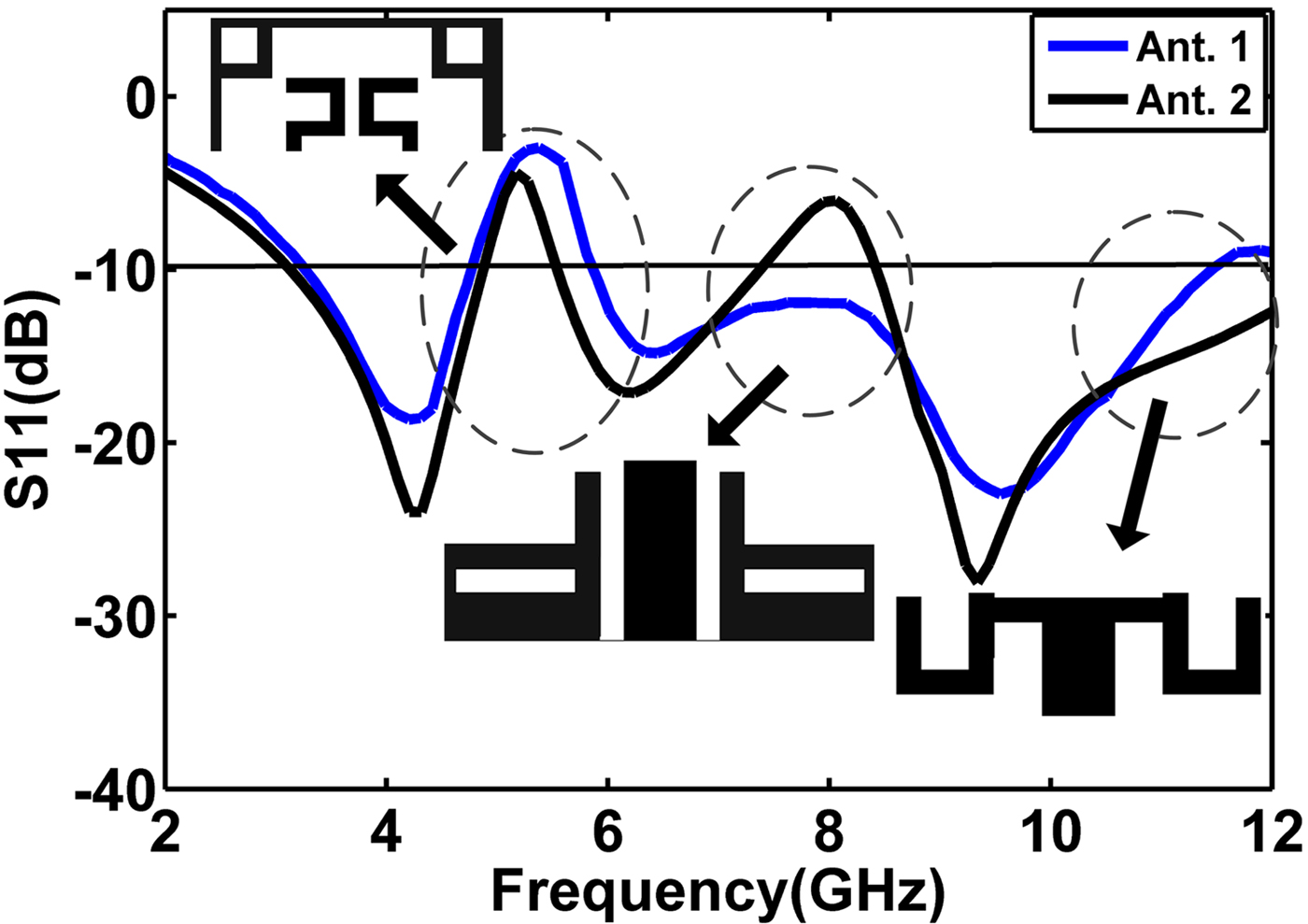
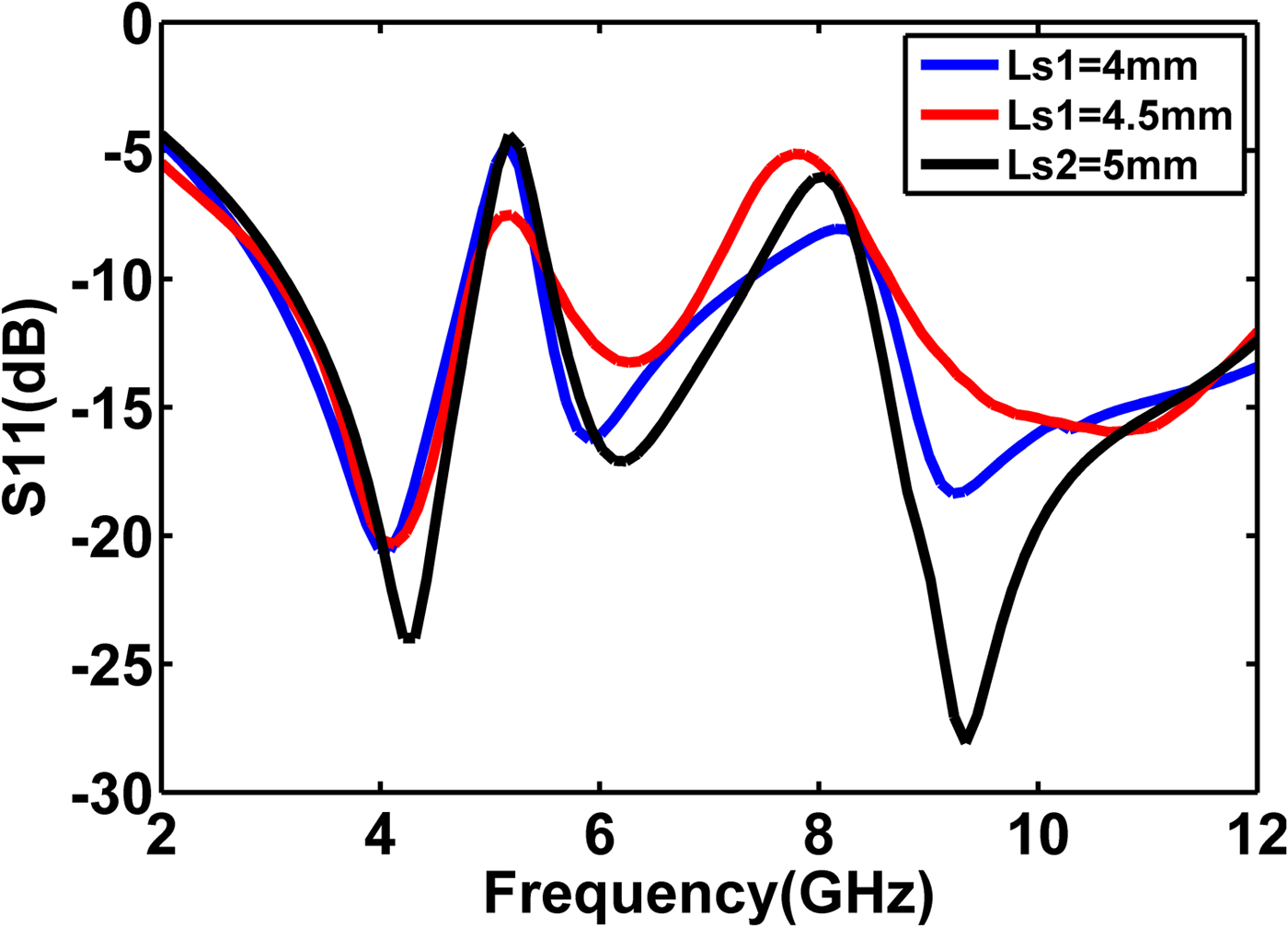
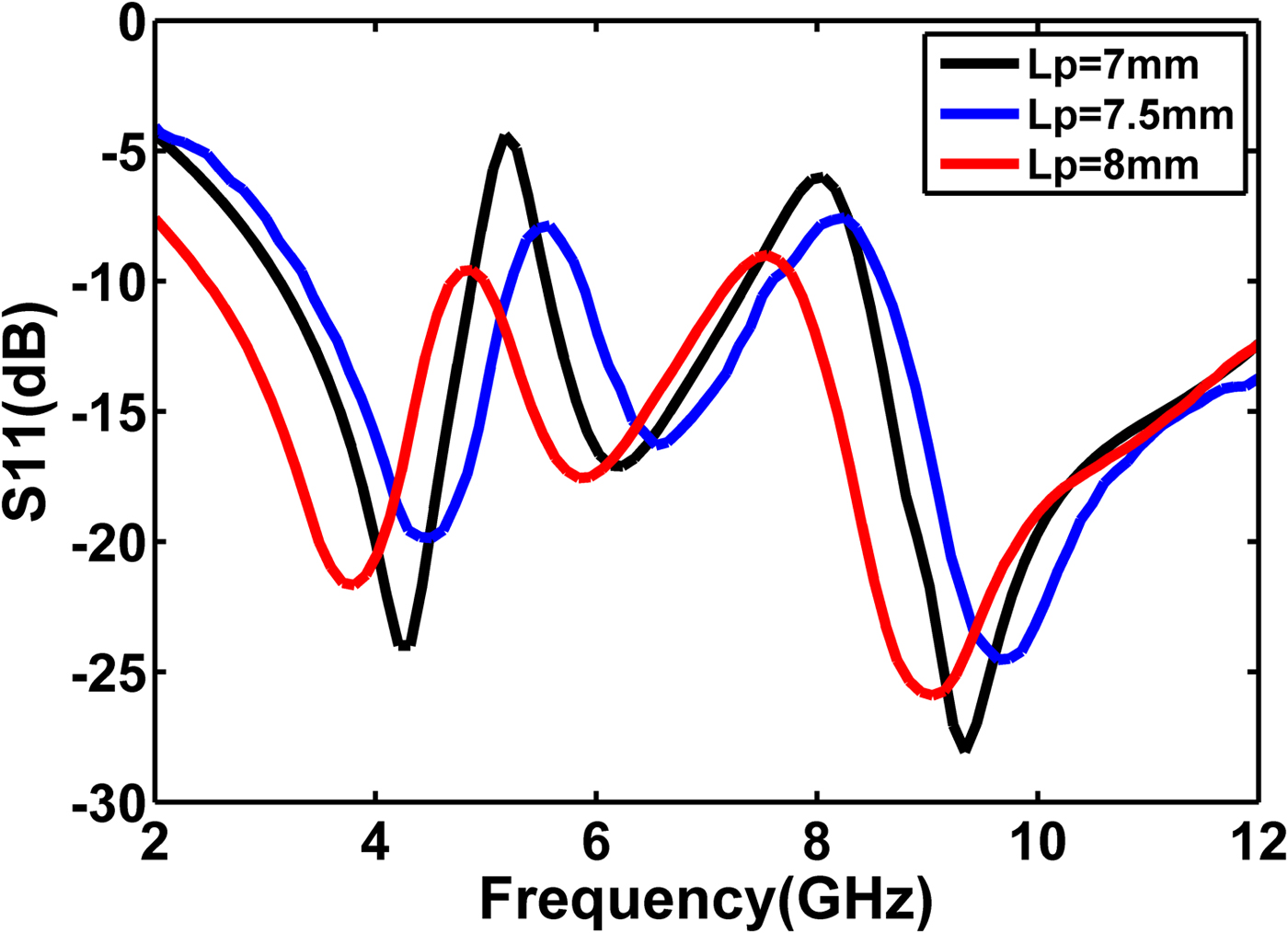
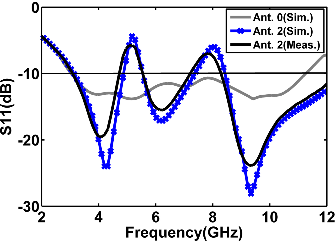
The layouts for all of CP-antennas (Ant. 0, Ant. 1, and Ant. 2) are optimized by Ansoft HFSS. First notched band (WLAN) is achieved by canceling the fields of the current flows inside U-shaped unit-cell semi-fractal strips at opposite directions. This surface current distribution leads to low effective radiation. The simulated return loss for Ant. 1 and Ant. 2 is studied in Fig. 6. These curves illustrate that the first rejected band is obtained by IMSF radiator at Ant. 1. Also, the second notched band (ITU-R) is achieved by MGDS that leads to ultimate CP-antenna (Ant. 2). The parametric study of initial patch and MGDS attached to Ant. 2 is discussed in Figs 7 and 8 for reconfiguration of stopped band. The L s1 and L p have important role at filtering characteristics and tuning functionality of Ant. 2. The length of MGDS has a significant role in ITU-R (7.725–8.5 GHz) stopped-band steering. Figure 7 shows low values of L s1, control the second rejected BWs of the final CP-antenna. Figure 8 illustrates L p parameter variations (high values of L p can control the first stop band). Also, it can be deduced by presenting UPMSF, the lowest frequency in first band is significantly shifted from 4 to 5 GHz. The notched bands centered at 5.5 and 8.1 GHz are rejected with S 11 larger than −4 and −5 dB for the WiMAX and ITU-R, respectively. The Ant. 2 was fabricated with PCB technology and measured with Agilent 8722ES VNA. Figure 9 illustrates antennas impedance BW. It is obvious that the ultimate antenna covers frequency range from 2.9 to 12.61 GHz (for S 11 < −10 db). The UPMSF radiator CP-antenna has two bands rejected at frequency ranges of 5–6 and 7.7–8.5 GHz (for S 11 > −10 dB). The axial ratio (AR) versus frequency is depicted in Fig. 10. Modified grounded L-shaped strips structure leads to achieve CP attribute at operational WiMAX IEEE802.16 (3.3–3.6 GHz) and C-band (3.7–4.2 GHz). Figure 11 exhibits the measured RHCP normalized radiation patterns and LHCP at 3.5 GHz for φ = 0o and 90o. Figure 12 demonstrates the variation of measured and simulated gain for Ant.1 and Ant. 2 versus frequency from 2 to 12 GHz. These curves represent that the fabricated antenna gain is decreased suddenly at the two stopped bands, but it has good gain flatness over the application bands. The measured far-field patterns of Ant. 2 are plotted in Fig. 13 for 7 and 9 GHz. In this plot, the black and red lines are the co-polarization and cross-polarization, respectively. The patterns are omni-directional radiation in the H-plane and dipole-like radiation in the E-plane. Because of semi-fractal configuration utilized in CP-antenna radiator, it has outstanding radiation performance and compact size. Table 2 lists comparison of the recently reported antennas in the literature with the proposed scheme for CP application.
S 11 simulation curves for Ant. 1 and Ant. 2.
Simulated S 11 for Ant. 2 for different values of L s1.
Simulated S 11 for Ant. 2 for different values of L p.
Simulated and measured S 11 of Ant. 0 and Ant. 2.
Measured and simulated AR for Ant. 1 and Ant. 2.

Simulated and measured LHCP and RHCP normalized radiation patterns for Ant. 2 at 3.5 GHz.

Simulated and measured gain of Ant. 1 and Ant. 2 (fabricated antenna).

Measured patterns of ultimate antenna (Ant. 2) (a) 7 GHz, (b) 9 GHz.

Performance comparison of the proposed antenna with other references

Conclusion
A unique design of CPW-fed antenna with broad-band characteristic, dual bands filtering features, and CP specification at WiMAX and C-bands is proposed. The dual-band-notched attribute can be regulated completely by inserting U-shaped unit-cell patterns of strips inside the semi-fractal patch and MDGS. Besides that, the number of U-shaped unit-cell patterns have major role in obtaining CP in 3.1–3.6 for WiMAX and C-bands. The real size of the compact square slot semi-fractal radiator antenna is limited to 25 mm × 25 mm × 1 mm and it operates across 2.9–12.61 GHz for VSWR <2, except the BWs of 5–6 GHz for WLAN and ITU-R (7.725–8.5 GHz). The proposed element has a CP BW from 2.9 to 4.1 GHz for AR <3 dB. The characteristics of proposed antennas are studied completely to understand their effects. The significant results obtained from the antenna analysis lead to optimize the antenna's entire performances. The prototype was realized to validate the characteristics, through laboratory measurements. The measured results affirm that the proposed antenna has a good impedance BW, dual-band filtering, CP attribute, and omni-directional radiation.
Acknowledgements
This research is the consequence of a project agreed with the research committee at Urmia Branch, Islamic Azad University. Authors would like to appreciate Urmia branch, Islamic Azad University, Urmia, Iran for its support. The authors would like to thank Prof. Bal Virdee for his valuable discussions and suggestions about the method of design.
 Tohid Sedghi received the B.Sc degree in Communication Engineering in 2007from IAU, Urmia Branch, Urmia, Iran. He received the M.S. degree in Electrical Engineering from the University of Urmia, Iran in 2009. He received his Ph.D. in 2015 from Science Research Branch, Islamic Azad Uinversity(IAU), Tehran, Iran. Dr. Tohid Sedghi joined Islamic Azad University, Urmia Branch, Iran, where he currently is an assistant professor and head of incubator center of technology units of Islamic Azad University, Urmia Branch. His main areas of interest in research are microstrip antenna, microwave passive and active circuits, RF MEMS, and metamaterial. He has published more than 30 papers in his referred international journal and more than 20 papers in national/international conferences.
 Mir Tohid Aribi received the B.Sc. degree in Electronic Engineering from IAU, Urmia Branch, Urmia, Iran, in 2005. He received the M.S. degree in Electrical Engineering from IAU, South Branch, Tehran, Iran, in 2008. His current interests are numerical techniques in electromagnetic, antenna, propagation, metamaterial and electromagnetic band gap (EBG) structure, substrate-integrated waveguide (SIW), and array antenna. Now he is an assistant professor at the Department of Electrical Engineering, Miandoab Branch, Islamic Azad University, Iran.
 Arash Kalami received the M.Sc. degree in Communication Engineering in 2005 from the Kermanshah University, Iran. He received his Ph.D. in 2015, from Science and Research Branch, Islamic Azad University, Iran. Dr. Kalami joined Islamic Azad University, Urmia Branch, Iran, where he currently is an assistant professor and head of graduate studies. His main areas of interest in research are microstrip antenna, microwave passive and active circuits, RF MEMS. He has so far published over 30 papers in different journals and conferences.