Introduction
Substrate-integrated waveguide (SIW)-based components contributed to the development of electronic systems operating in the microwave and millimeter wave frequency ranges, such as 5 G networks [Reference Chi, Shih and Yang1]. The significance of using SIW interconnects in high-performance applications has increased with the rise in system clock frequencies, particularly during the global health crisis, as healthcare systems encounter unprecedented challenges due to the spread of the coronavirus [Reference Vedaei, Fotovvat, Mohebbian, Rahman, Wahid, Babyn, Marateb, Mansourian and Sami2]. Network industries currently focus on developing solutions to efficiently utilize the underutilized spectrum in the millimeter wave frequency band, known as the high-frequency 5 G band [Reference Andrews, Buzzi, Choi, Hanly, Lozano, Soong and Zhang3]. This band operates within a frequency range of 25–100 GHz, offering high frequency and unique propagation characteristics. These characteristics are suitable for various applications, such as facilitating the efficient transmission of significant amounts of data like medical systems. Biomedical telemetry technology, which allows for monitoring patients’ physiological signs, has gained popularity in the healthcare industry [Reference Tebe, Chong, Zhang, Yang, Tian and Wen4] due to its potential applications in the internet of things (IoT) [Reference Ang and Seng5, Reference Marques, Han, Wu and Madeiro6]. The antenna plays a crucial role in transmitting and receiving data is critical, particularly in the development of artificial intelligence (AI) patient monitoring systems, medical applications [Reference Zhai, Xu, Chen, Lu, Wang, Li, Shi, Wang, Shang and Zhao7], and implanted antennae [Reference Abbas, Basir, Iqbal, Yousaf, Akram and Yoo8, Reference Noormohammadi, Khaleghi and Balasingham9] in the body or wearable devices with AI technology [Reference Musci, De Martini, Blago, Facchinetti and Piastra10].
The decision to design three SIW antennas, including a single SIW antenna, a two-array SIW antenna, and a four-element SIW antenna, was driven by the various requirements and applications in the fields of medicine, 5 G-enabled IoT applications [Reference Pandey, Sahu, Gangwar and Chaudhary11], and AI [Reference Jagatheesaperumal, Pham, Ruby, Yang, Xu and Zhang12, Reference Sharma, Vineeta, Som and Khatri13].
For instance, the single SIW antenna design was selected to fulfill the need for seamless wireless communication. It enables real-time monitoring [Reference Xie, Liu, Zhang and Cheng14] and remote patient care in medical applications by facilitating reliable communication between medical devices and healthcare providers.
The two-array SIW antenna design was developed to address the demand for medium-range wireless communication. Medical applications benefit from increased signal strength and reliability in remote patient monitoring systems, like smart hospitals, by connecting intelligent devices [Reference Zhang, Li, Wen, Xun and Liu15], such as wearable health devices.
The four-element SIW antenna design was developed to meet the requirements of high-gain and long-range wireless communication. In medical applications, it enhances signal control and imaging quality in high-resolution medical imaging systems like MRI or CT scanners [Reference Georgescu, Ionescu and Verga16].
Designing three SIW antennas tailored for specific application requirements guarantees effective and dependable wireless communication in medical, IoT [Reference Ghubaish, Salman, Zolanvari, Unal, Al-Ali and Jain17], and AI systems, enabling advancements in these fields.
The high gain and wide bandwidth of the SIW antenna ensure consistent and reliable high-speed communication, one of the important applications we are currently working on involves using an SIW-primarily based antenna to enhance mobility answers for individuals with disabilities, by way of integrating this antenna into smart wheelchairs [Reference Soma, Patil, Salva and Jadhav18], which is critical for features such as remote control, real-time GPS [Reference Andrea, Sauro and Andrea19] tracking, and obstacle detection systems.
The smart wheelchair supports various user interfaces, including joysticks, voice commands [Reference Perera, Gamage, Weerasinghe, Jayawardena, Pathinayake and Rajapaksha20], mobile applications, and EEG [Reference Joshi, Soni, Joshi, Vyas and Joshi21]-based systems. The proposed antenna guarantees uninterrupted connectivity, enabling seamless interaction with the control system regardless of the method chosen by the user.
The compact design of the SIW antenna allows for seamless integration into the wheelchair without affecting its aesthetics or functionality. This ensures that the device remains user-friendly and visually appealing while delivering high performance.
In [Reference Kumar, Bhaskar and Singh22], two cavity-backed slot antennas based on SIW technology were designed for use in 5 G applications. The first antenna was designed with a U-shaped slot instead of a slender rectangular slot, utilizing inductive loading to enhance bandwidth. This antenna covered the 28 GHz (27.5–28.35 GHz) band and exhibited a gain of 7.15 dBi. The overall volume, including the feed line, was 20 mm × 14 mm × 0.508 mm.
In [Reference Kumar, Bhaskar, Singh, Khan and Singh23], the second antenna is a wideband dual-resonance slot antenna with a cavity backing designed to operate at frequencies of 24.25 and 27.5 GHz. Hybrid modes were generated in the desired frequency band by positioning hybrid modes and incorporating multi-resonant slots on the lower metal cladding of the SIW cavity. The slot parameters can be adjusted to merge different resonance frequencies. The antenna provided a gain of 7.8 dB, and the overall volume, including the feed line, was 18 mm × 12 mm × 0.508 mm.
In [Reference Ghalib and Mohammad24], a new SIW utilizing a longitudinal slot array was developed. The design optimized the placement of slots on the surface of the SIW to achieve a bandwidth of 3 GHz, ranging from 27 to 30 GHz. This encompasses the upcoming 5 G frequency bands. The antenna directs radiation toward the wide side with a side lobe level of at least 10 dB. It has a maximum gain of 9.18 dB and measuring a size of 62 mm × 7.23 mm.
In [Reference Ashraf, Haraz, Ashraf and Alshebeili25], a design for a linearly polarized dual-band SIW antenna/array that operates at Ka-band. The single antenna element consists of an SIW cavity with two longitudinal slots resonating at 28 and 38 GHz. The CST microwave studio software demonstrates the design of a 1 × 4 horizontally polarized linear array using a microstrip line feed network with a 3-dB Wilkinson power divider to achieve high gain. The simulations show that the antenna array has an impedance bandwidth of 1.9 GHz with a maximum gain of 11.2 dBi at 28/38 GHz, respectively. The proposed designs use a low-loss/cost substrate of RT/Duroid 5880.
In [Reference Li, He and Song26], the study introduces a broadband millimeter wave (mmWave) base station antenna with a filtering function and designed with the usage of a SIW shape. The antenna consists of two patch elements, sets of L-shaped probes, and an SIW-primarily based feeding device. A wide bandwidth is executed through incorporating a defected ground structure (DGS) and barbell slot into the SIW, along with a differentially fed L-shaped probe. Additionally, the filtering characteristic is accomplished by using etching H-fashioned slots onto every patch and exceptional-tuning the SIW and probe configuration. Simulation results show an impedance bandwidth of 23.72–29.90 GHz, with a found-out benefit exceeding 6.3 dBi. The proposed filtering antenna is designed as a multilayer structure. It makes use of two one-of-a-kind forms of substrates; each selected for its unique fabric homes to optimize performance. The upper and middle substrates (called substrate 1 and substrate 2) are crafted from Rogers RT/duroid 5880, which has a dielectric constant of 2 and a loss tangent of 0.0009. The thickness of substrate 1 is 0.787 mm, and the thickness of substrate 2 is 0.6 mm. The lowest substrate (substrate 3) uses Rogers RO4003, which has a dielectric constant of 3.55 and a loss tangent of 0.0027. Substrate 3 has a thickness of 0.4 mm.
In [Reference Mihad, Kawsari, Parveen, Rani and Rahman27], the work introduces a modern twin-band slotted patch antenna designed mainly for 5 G cell verbal exchange programs. The antenna measures 7.91 × 7.85 × 0.32 mm3 and includes four rectangular slots together with one circular slot, all strategically placed on its radiating floor. The design and evaluation have been carried out with the usage of a Rogers RT6002, a substrate with proper dielectric properties (relative permittivity εr = 2.94 and loss tangent tan δ = 0.0012). Simulations were carried out inside the CST microwave studio software program. The results confirmed commendable performance, with profits of 5.87 and 5.404 dBi, in addition to impedance bandwidths of 686 MHz and 1.983 GHz at resonant frequencies of 28 and 37 GHz, respectively. This antenna is identified as a promising and effective alternative for advancing 5 G cell conversation technology.
In [Reference Singh and Pal28], this letter proposes a compact, self-isolated, extraordinarily low correlated 1 × 4 folded-SIW-based slot antenna configuration for 5 G multiple-input–multiple-output (MIMO) communication which is operating at the 38 GHz band. The antenna makes use of a T-type folded SIW (TFSIW) feeding machine and is designed on the Rogers RT6002. The total MIMO size is 9.8 × 38.64 × 0.508 mm3 and it has a maximum gain of 10 dBi.
In [Reference Modak, Lokam and Farooq29], this study presents a self-isolated quad-port MIMO antenna tailor-made for 5 G wireless communication. The antenna’s ordinary dimensions are 12.4 mm × 12.4 mm × 0.508 mm and it is based on an unmarried-detail layout that consists of a circular patch at the side of a sectoral slot. To obtain the preferred frequency variety, a further circular patch is strategically placed above the primary radiator. The layout system of the antenna is analyzed through the lens of the feature mode idea. This multi-detail configuration gives an extensive operational bandwidth of 4.5 GHz, overlaying frequency ranges from 26.1 to 30.6 GHz, making it appropriate for the mmWave bands at n257, n258, and n261. The antenna demonstrates a gain of 6.27 dBi.
In [Reference Metahri, Abri and Moussaoui30], this study introduces a revolutionary log-periodic dipole antenna array utilizing with the aid of employing SIW. The antenna shape is streamlined, resulting in decreased losses. The design and simulation of the antenna array were carried out inside the mmWave frequency range of 22–40 GHz. The antenna model is fabricated on a Rogers RT5880 substrate, measuring 0.508 mm in height and having a relative permittivity of 2.2. Simulation effects received using the CST simulator demonstrate that the antenna array operates efficaciously at 26.86 GHz, featuring a go-back loss of about −45.62 dB and an average benefit of around 7.62 dBi.
This paper introduces the design of a compact SIW antenna, including a single SIW, a 2 × 1 array, and a 4 × 1 array, with and without a slot. H-shaped and U-shaped slots are incorporated inside the patch to improve the impedance matching and the performance of the SIW antenna. Moreover, a KS connector is integrated into the feeding network of the proposed design to improve the matching. The proposed SIW antennas are designed to operate around 26 GHz and within the frequency range of 25–28 GHz. Further, the configurations, design parameters, and the simulated results of the suggested SIW antenna including the single and the arrays without and with slots are presented and discussed in this study. For verifications, the array of 4 × 1 SIW antenna is fabricated, measured, and tested with result discussions. Accordingly, the 4 × 1 SIW array achieves a gain of 14.7 dBi, a directivity of 15 dBi, and a measured bandwidth of more than 1.9 GHz at the resonance frequency of 26 GHz. These results confirm the performance of the proposed design compared to different configurations within the frequency band.
SIW slot antenna designs
A SIW slot antenna design
The proposed SIW antenna operates by guiding electromagnetic waves through a SIW structure. The SIW technology utilizes a substrate with two parallel rows of metallic vias, which effectively confine the electromagnetic waves within the desired path and minimize leakage. These vias act as side walls, similar to those in a rectangular waveguide, ensuring that the energy is efficiently transmitted in a unidirectional manner while preventing unwanted radiation losses.
The incorporation of slots into the SIW structure significantly enhances the antenna’s performance. Slots are strategically placed to improve impedance matching, enabling a reduction in the reflection coefficient (S11) and facilitating better energy transfer between the antenna and the feeding structure. Additionally, the slots influence the surface current distribution on the antenna, leading to improved radiation efficiency and higher gain. Specifically, the H-shaped and U-shaped slots introduced in the design optimize the current flow, resulting in better directional characteristics and a broader bandwidth.
When designing a SIW, it is essential to consider the size and placement of via holes. The diameter (d), distance between two via holes (s), and distance between the two rows of via holes (a) are the three primary parameters to consider. The spacing-to-diameter ratio should be less than or equal to 2 (s/d ≤ 2) and the diameter of the via hole should not be less than the substrate thickness (V > h) due to fabrication limitations. A via diameter of 0.8 mm and a spacing of 1.1 mm were chosen for optimal performance to ensure minimal leakage loss between the posts and have negligible impact on the SIW’s performance. Here, the design equations for the spacing condition, antenna width, adjusting actual width, and the guided wavelength.
 \begin{equation}\left(s\text{ }/\text{ }d\right)\text{ }\leqslant\text{ }2\;,\end{equation}
 \begin{equation}b=\frac{\lambda o}{\sqrt{2\left(\varepsilon r+1\right)}}\;,\end{equation}
 \begin{equation}Ar=\,Ae+\frac{D^2}{0.95P}\;,\end{equation}
 \begin{equation}\lambda g\,=\,\frac C{\text{ }f\sqrt{\in r}}\;.\end{equation}
Here, s is the spacing between antenna elements, d is the diameter of the antenna elements, b is the antenna width,  $\lambda o$ is the wavelength in free space, εr is the relative permittivity of the substrate, Ar is actual width of the SIW, Ae is the equivalent width of the rectangular waveguide, D is the design factor (specific to the SIW design), P is the parameter related to via spacing, 0.95 is the scaling factor for practical adjustments,
 $\lambda g$ is the guided wavelength within the material, C is the speed of light in a vacuum, and f is the resonant frequency (Hz).
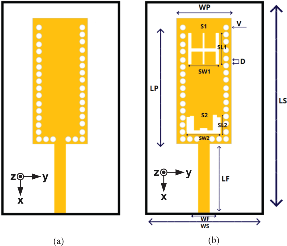
The 28 GHz SIW antenna requires vias with a diameter smaller than 2 mm (V < 2 mm), and the space between vias should be less than 1.6 mm (D < 1.6 mm). Equation (2) was used to draw the slot equation, while equations (3) and (4) were used to determine the distance between the two columns of vias and two slots, resulting in the H-shaped S1 slot and the U-shaped S2 slot, as depicted in Fig. 1.
The structure of SIW antenna. (a) Without slot. (b) With slot.

Figure 1(b) shows the geometry and indicating the design parameters of the proposed single-element SIW antenna. Moreover, a reference coordinate system (x, y, and z) is included to indicate the antenna orientation, where x and y lie on the substrate surface and z represents the radiation direction.
When designing a rectangular SIW antenna, the width and height dimensions of the waveguide are crucial factors as they determine its cutoff frequency. The primary mode in a rectangular waveguide is the TE10 mode. The rectangular SIW waveguide supports various propagation modes, and the TE10 mode is typically the dominant mode. In this mode, the electric field is transverse to the direction of propagation, whereas the magnetic field is primarily parallel to the direction of propagation.
The cutoff frequency of the rectangular SIW waveguide is determined by its dimensions, specifically the width and height of the waveguide. The dimensions are usually selected to ensure that only the desired mode (such as TE10) is supported and propagated within the waveguide, while higher-order modes are attenuated or prevented.
By precisely selecting the width and height of the rectangular SIW waveguide, achieving the desired operating frequency range and ensuring efficient transmission and reception of electromagnetic waves is possible. The values of key parameters for SIW antennas are displayed in Table 1.
The Parameters of SIW Antenna

The antenna design utilized the Roger RT 5880 substrate, which is appropriate for millimeter-wave frequencies, and copper was used for the ground. The substrate has a relative dielectric constant (εr) of 2.2 and a loss tangent (tan δ) of 0.0009, with a substrate thickness (h) of 0.508 mm and a copper thickness (t) of 0.035 mm.
Figure 2 (a) demonstrates the simulated the reflection coefficient of the suggested antenna, achieving a bandwidth of 2.8 GHz centered at 26.5 GHz with a reflection of less than −10 dB over the required bandwidth. However, further enhancement is necessary to increase the bandwidth. The single SIW antenna showed appropriate gain and efficiency, as demonstrated in Figs. 2(b) and 2(c), respectively.
Simulated performance of the proposed SIW antenna with and without slot. (a) Reflection coefficient (S11) across 25–28 GHz. (b) Realized gain versus frequency. (c) Radiation efficiency versus frequency.

Figure 3(a) displays the 2D polar radiation pattern of the suggested antenna in both E- and H-planes. One plot depicts the main structure’s E-plane with a slot and the other without a slot. In addition, Fig. 3(b) shows the H-plane radiation pattern of the SIW antenna (with and without a slot).
Simulated radiation patterns of the SIW antenna at 26.5 GHz. (a) Co-polarization (θ-component) in the E-plane (φ = 0°), with and without slot. (b) Co-polarization (φ-component) in the H-plane (φ = 90°), with and without slot. (c) Cross-polarization patterns in both E-plane and H-plane, with and without slot.

2 × 1 SIW slot antenna array design
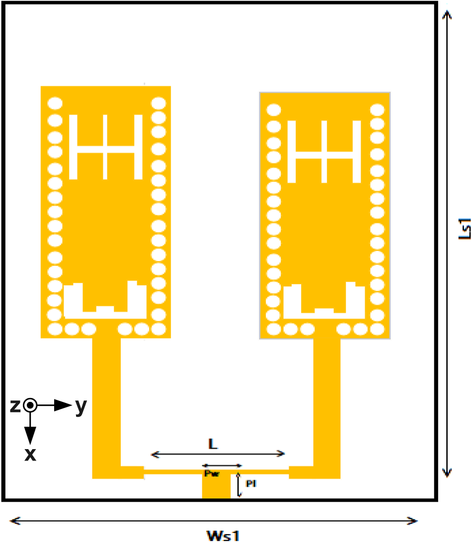
The next section of this work is to modify the structure from a single SIW antenna to a 2 × 1 SIW array antenna operating at 26.5 GHz while maintaining the same antenna design and dimensions as in the previous section. However, the antenna element is duplicated to be a two-element array, changing the substrate’s length and width (Fig. 4 and Table 2).
The structure of a 2 × 1 SIW antenna with slot.

The Parameters of 2 × 1 SIW Antenna

The reflection coefficient of the SIW array antenna (with and without a slot) is depicted in Fig. 5(a). The two-element SIW antenna array has achieved adequate gain and efficiency for 5 G healthcare applications, as depicted in Figs. 5(b) and 5(c), respectively.
Simulated performance of the proposed 2 × 1 SIW antenna with and without slot. (a) Reflection coefficient (S11) versus frequency. (b) Realized gain versus frequency. (c) Radiation efficiency versus frequency.

Figure 6(a) displays the 2D polar radiation patterns of the proposed antenna in both E- and H- planes, with one plot depicting the E-plane of the main structure (with and without a slot). Figure 6(b) shows the H-plane radiation patterns of the SIW antenna (with and without slots). Further, the asymmetry observed in the green line of the radiation pattern is attributed to the effect of the slot on the radiation characteristics.
Simulated radiation patterns of the 2 × 1 SIW antenna at 26.5 GHz. (a) Co-polarization (θ-component) in the E-plane (φ = 0°), with and without slot. (b) Co-polarization (φ-component) in the H-plane (φ = 90°), with and without slot. (c) Cross-polarization patterns in both E-plane and H-plane, with and without slot.

4 × 1 array antenna at 26 Ghz
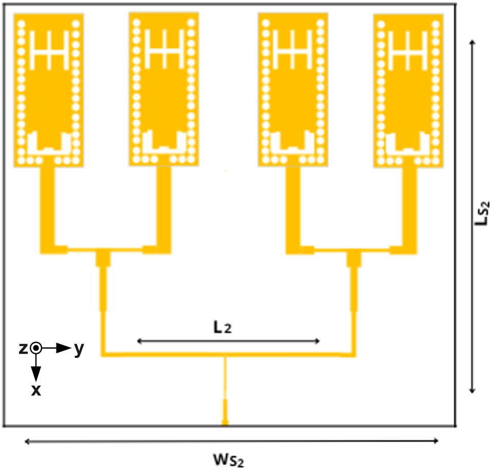
This part of the work involves modifying the structure from a single SIW antenna to a 4 × 1 SIW antenna array operating at 26 GHz, maintaining the same antenna design. The duplicated antenna is a two-element array that caused alterations in substrate length, width, and feed line, as shown in Fig. 7. Additionally, Table 3 depicts the dimensions of the proposed design.
The structure of a 4 × 1 SIW antenna with slot.

The dimensions of the 4 × 1 array antenna design

Figure 8(a) demonstrates the reflection coefficient of the SIW array antenna with a slot. The SIW array antenna used in this study achieved a suitable gain of 26 GHz, as shown in Fig. 8(a). In addition, the radiation efficiency of the SIW array antenna is demonstrated in Fig. 8(c). Further, Fig. 9(a) displays the 2D radiation pattern of the SIW array antenna, demonstrating the E-plane with and without a slot. In the E-plane of this work, the directive beam can also see the effect of the slot, making the beam radiate at zero angle. In addition, Fig. 9(b) shows the H-plane radiating pattern of the design.
Simulated performance of the proposed 4 × 1 SIW antenna with and without slot. (a) Reflection coefficient (S11) versus frequency. (b) Realized gain versus frequency. (c) Radiation efficiency versus frequency.

Simulated radiation patterns of the 4 × 1 SIW antenna at 26 GHz. (a) Co-polarization (θ-component) in the E-plane (φ = 0°), with and without slot. (b) Co-polarization (φ-component) in the H-plane (φ = 90°), with and without slot. (c) Cross-polarization patterns in both E-plane and H-plane, with and without slot.

Fabrication and results of the proposed 4 × 1 SIW antenna array
In this section, a comparison between the measurement and simulation results of a SIW component is presented. The SIW component was designed and fabricated using the Roger RT 5880 substrate and copper in the ground. The measurements were conducted using a vector network analyzer (VNA) with KS connectors to connect the antenna to the measurement and simulation equipment while the simulation was performed using CST. This comparison aims to evaluate the accuracy of the simulation results for the SIW component and to assess its performance in a real-world scenario. Furthermore, we aimed to compare the simulated and measured reflection coefficient, gain, and efficiency as well as to determine the degree of agreement between both.
The comparison revealed good agreement between the measurement and simulation results for the reflection coefficient, gain, and efficiency. The simulation accurately predicted the performance of the SIW component, demonstrating that the SIW technology is suitable for its intended application. The KS connector plays a crucial role in seamlessly integrating the SIW antenna into high-frequency systems. Optimized for PCB end-launch applications, it facilitates stable signal transmission with minimal attenuation. Constructed from gold-plated brass, it offers superior electrical conductivity and corrosion resistance, making it ideal for millimeter-wave technologies such as 5 G. In this design, the KS connector is affixed to the PCB and links to the antenna array via a narrow copper feed line as shown in Figs. 10(a) and 10(f), which enhances impedance matching and minimizes signal reflections, ultimately boosting the antenna’s gain and overall efficiency. It was constructed and evaluated to confirm the proposed 4 × 1 SIW antenna array design. Figures 10(a) and 10(b) show photographs of the manufactured prototype, whereas Fig. 10(c) displays the estimated return loss (S11) of the proposed antenna and Fig. 10(d) presents the antenna under test positioned inside the anechoic chamber. Moreover, Fig. 10(e) offers a close-up view of the fabricated antenna under radiation measurements. The coaxial cable connection and absorber-lined measurement surroundings are clearly shown, ensuring minimal reflections and accurate measurement results and including the VNA used during testing. The obtained results suggest that the antenna is appropriate for AI and IoT healthcare applications.
Photographs of the fabricated 4 × 1 SIW antenna. (a) Top view. (b) Bottom view. (c) Reflection coefficient measurement using the VNA. (d) Antenna under test inside the anechoic chamber. (e) Close-up of the antenna during radiation pattern measurements. (f) K-type connector.

The simulation and measurement reflection coefficients of the SIW array antenna are depicted in Fig. 11(a). A satisfactory level of concurrence is thus achieved between the two plots. As shown in Fig. 11(b), the SIW array antenna that was proposed in this study achieved a suitable gain at 26 GHz as shown in Fig. 11(b) and compared to the measured one. Furthermore, as demonstrated in Fig. 11(c), the SIW array antenna exhibited a practical level of radiation efficiency. Figure 11 shows good correspondence for all comparisons of the measured parameters of the antenna with the simulated data.
Measured and simulated performance of the proposed 4 × 1 SIW antenna. (a) Reflection coefficient (S11) versus frequency. (b) Realized gain versus frequency. (c) Radiation efficiency versus frequency.

Figure 12 shows the 2D radiation patterns of the SIW array antenna. Figure 12(a) presents the simulated and measured E-planes. Further, Fig. 12(b) shows the H-planes of the design, and there is a good matching between the plotted data.
Measured and simulated radiation patterns of the proposed 4 × 1 SIW antenna at 26 GHz. (a) Co-polarization (θ-component) in the E-plane (φ = 0°), showing both measured and simulated results. (b) Co-polarization (φ-component) in the H-plane (φ = 90°), showing both measured and simulated results. (c) Cross-polarization patterns in both E-plane and H-plane, with and without slot, including measured and simulated data.

In Table 4, a comparison is presented between the proposed design and previously reported millimeter-wave SIW antennas in terms of operating frequency, number of elements, gain, and slot shape. The proposed design exhibits superior performance, achieving the highest gain and efficiency across single-, two-, and four-element configurations. These results are validated through both simulation and experimental measurements, confirming the effectiveness of the proposed antenna structure.
Comparison of the results obtained for the proposed design compared with the studies in literature

Conclusion
An antenna with low loss and compact size is essential for millimeter-wave frequencies, such as those used in 5 G healthcare systems. The proposed SIW antennas were designed to operate around 26 GHz, within the broader 25–28 GHz frequency band. Low-loss performance was achieved due to the presence of vias along the antenna’s edges. These vias guide the signal unidirectionally and enhance the directivity of the SIW. The CST simulation software was used to design and analyze the proposed SIW structures. The results of the single SIW antenna show a gain of 8.5 dBi and a directivity of 9 dBi at 26 GHz, with a bandwidth of more than 2.8 GHz. The 2 × 1 array antenna has a gain of 12.9 dBi, a directivity of approximately 13.4 dBi, and a bandwidth of more than 1.8 GHz. Finally, the 4 × 1 array antenna achieved a gain of 14.7 dBi, a directivity of 15 dBi, and a measured bandwidth of more than 1.9 GHz. These results confirm the scalability and efficiency of the proposed design across different configurations within the target frequency band.
Competing interests
The authors declare none.

Merna Mohamed Abdelsattar received the B.Sc. degree in Electronics and Communication Engineering from the Arab Academy for Science, Technology & Maritime Transport, Egypt, in 2017, and the M.Sc. degree in Electronics and Communication Engineering from South Valley University, Egypt, in 2025. She is currently serving as Head of Research and Development at SCOOPe, leading projects in medical simulation, endoscopy simulators, and Virtual Reality (VR) technologies aimed at enhancing medical training and diagnostic systems. She also works as a Biomedical Engineer, focusing on innovative device design and the integration of intelligent systems in healthcare. Her research interests include antenna design, artificial intelligence (AI), machine learning, deep learning, neural networks, computer interfaces (BCI), Virtual Reality (VR), prosthetics, and Internet of Things (IoT) applications in healthcare.

Mohamad Abou Houran Dr. Houran is an Associate Professor and PhD supervisor in the School of Electrical Engineering at Xi’an Jiaotong University (XJTU), where he joined as an Assistant Professor in 2020 through the Young Talent Program. His research focuses on Power Electronics, particularly Wireless Power Transfer (WPT) systems, Electromagnetics, and Machine Learning. Dr. Houran has led and completed two national-level research projects, including grants from the National Natural Science Foundation of China (NSFC) and the Ministry of Science and Technology. He is currently serving as the Principal Investigator of other research grants like Shaanxi Province Key R&D Project, funds of XJTU, and Co-PI of a Key R&D National Project. He has authored over 65 peer-reviewed publications and holds several patents. Dr. Houran is an IEEE Senior Member and serves as a reviewer for leading IEEE journals, including IEEE Transactions on Power Electronics, IEEE Transactions on Industrial Electronics, the IEEE Journal of Emerging and Selected Topics in Power Electronics, and IEEE IAS Publications among others.

Yasser Ahmed Dahab is an Associate Professor of Computer Science at the Arab Academy for Science, Technology and Maritime Transport, South Valley Branch, Egypt. He earned his Ph.D. in Information Technology from Cairo University and a master’s degree in Computer Science from Friedrich-Alexander University Erlangen–Nürnberg, Germany. His research focuses on artificial intelligence, deep learning, and intelligent systems, with notable publications in IEEE Access and PLOS One. Dr. Dahab has contributed to several educational and technological initiatives. He specializes in AI teaching, curriculum development, and applied IT solutions for education and development.

Adel B. Abdel-Rahman Adel B. Abdel-Rahman received his B.S. and M.S. in Electrical Engineering, Communication, and Electronics from Assiut University, Egypt, and his Dr.-Ing. degree in Communication Engineering from Otto von Guericke University, Germany in 2005. Since October 2006, he has been a Professor at the Electrical Engineering Department, Qena University, Qena, Egypt. He has published more than 150 refereed journal and conference papers. He holds one patent (DE10322803A1) and one book (ISBN: 978-981-13-8047-1). He was the Executive Director for Information and Communication Technology, South Valley University, from 2010–2012. Since October 2012, he joined the School of Electronics, Communications and Computer Engineering, Egypt-Japan University of Science and Technology (E-JUST), Alexandria, Egypt, and has been the Dean of the Faculty of Computers and Information, South Valley University from 2016–2018. His research interests include the design and analysis of antennas, filters, millimeter-wave devices, WPT, FSS, and metamaterials and their application in wireless communication, as well as optimization techniques with applications to microwave devices and antenna arrays. He is included in several biographical indexes and acts as reviewer in many international societies in his field as IEEE MTT. He has been selected as a member of the promotion to Professors and Associate Professors Scientific Committee for Electronics and Communications, Supreme Council of Universities, Committee no. 14, 2022–2025.

Hany A. Atallah was born in Qena, Egypt. He received his B.Sc. and M.Sc. in Electrical Engineering, Electronics and Communications from South Valley University, Egypt, in 2007 and 2012, respectively. The Ph.D. degree in antennas and microwave engineering at Egypt–Japan University for Science and Technology (E-JUST). He is currently working as an associate professor at the Electrical Engineering Department, Electronics and Communications Engineering, Qena Faculty of Engineering, Qena University. He was a Visiting Researcher with the E-JUST Lab, School of Information Science and Electrical Engineering, Kyushu University, Japan, from September 2015 to July 2016. Dr. Hany serves as a Technical Reviewer for several prestigious ranked journals as AEUE - International Journal of Electronics and Communications, IEEE Internet of Things, IEEE Access, IET Microwaves, Antennas & Propagation, IET Electronic Letters, Applied Computational Electromagnetic Society (ACES), Advanced Electromagnetics (AEM), and progress in electromagnetics research (PIER). His research interests include antenna design, dielectric resonators, metamaterials, tunable filters, reconfigurable antennas, antenna arrays, microwave filters, and FDTD. His recent research has been on cognitive radio (CR) antennas, wireless power transfer (WPT) for biomedical implants, electric vehicles, and electronic devices, breast cancer detection, smart meters, AI, Machine Learning, Deep Learning Neural Networks, and the internet of things (IoT).