I. INTRODUCTION
Nanocrystalline (NC) materials have been studied with great interest by many researchers and applied in various fields because of their unique mechanical properties. In comparison with traditional coarse-grained materials (whose grain size is above several micrometers), NC materials usually have lots of outstanding performance, such as superior strength, strong hardness, and better wear resistance. Unfortunately, most of NC materials show low tensile ductility and fracture toughness, which limits their application. However, there are some NC materials with good tensile ductility that have been produced and reported. For instance, Youssef et al. Reference Youssef, Scattergood, Murty, Horton, Koch and Carolina1 reported that their nanostructured Cu sample had a uniform tensile elongation of 14% and an elongation-to-failure of 15.5%. Shan et al. Reference Shan, Stach, Wiezorek, Knapp, Follstaedt and Mao2 observed experimentally that there are no porosities or intergranular microcracks in Ni sample with an average grain size of 9.7 ± 3.9 nm after deposition. It is well known that the property of corresponding bulk materials is dependent on their microstructure, hence, understanding of the fundamentals of superplasticity, especially the deformation mechanisms during the loading process, is of great importance to extend the application of NC materials.
In conventional coarse-grained metals, the lattice dislocation slip plays a dominant role during the deformation process. However, when the grain size decreases down to nanoscale, the volume fraction of grain boundaries (GBs) increases and the lattice dislocation slip is suppressed. Meanwhile, some other GB-related deformation modes such as intergrain sliding, Reference Mukherjee3–Reference Monk, Hyde and Farkas7 coble creep, Reference Yang and Yang8,Reference Yang and Yang9 twin crystal deformation, Reference Gutkin, Ishizaki, Kuramoto, Ovid’ko and Skiba10 and rotational deformation Reference Shan, Stach, Wiezorek, Knapp, Follstaedt and Mao2,Reference Zizak, Darowski, Klaumünzer, Schumacher, Gerlach and Assmann11–Reference Li, Zhou, Zhu, Liu and Jiang16 are responsible for the deformation. These mechanisms occur in NC materials and have been theoretically studied either by experiments or by computer simulations.
It is well known that the stress concentration near the crack tip in NC materials can generate edge dislocations and induce plastic shear when the dislocations are emitted from the crack tip. Reference Gutkin, Ishizaki, Kuramoto, Ovid’ko and Skiba10,Reference Asaro, Krysl and Kad17 According to the study by Ovid’ko and Sheinerman, Reference Ovid’ko and Sheinerman18 the process of crack blunting and growth depends on the emission of dislocations near the crack tips. That means GB sliding mechanism is closely related to the fracture toughness of NC materials with a crack. Lots of computer simulations Reference Van Swygenhoven and Derlet6,Reference Monk, Hyde and Farkas7,Reference Latapie and Farkas19 and experimental data Reference Mukherjee3,Reference Koch4,Reference Xu, Nishimura, Hirosaki, Xie, Yamamoto and Tanaka20 have shown that GB sliding is one of the key mechanisms of plastic deformation in NC metals. Fedorov et al. Reference Fedorov, Gutkin and Ovid'ko21 made an intensive study of the transformations of GB dislocation pile-ups at triple junctions and the energy characteristics. They found that there may be several types of transformations of GB dislocations when they passed through triple junctions. One of the cases is that the head pile-up dislocation splits into two mobile dislocations that move along adjacent GBs, respectively. However, sometimes the head dislocation splits into an immobile GB dislocation which stays at the triple junction and a mobile dislocation which moves along one of the adjacent GBs. Another case is that the mobile partial dislocation moves into grain interior and leads to the formation of stacking fault behind the moving dislocation. The main aim of this paper is to theoretically describe the effect of GB sliding on the fracture toughness of NC materials which contain finest grains.
The distribution of grain size in NC materials usually follows the role of log-normal. Youssef et al. Reference Youssef, Scattergood, Murty, Horton, Koch and Carolina1 reported such a log-normal grain size distributions based on their experimental observation. The bulk NC Cu spheres (with an average grain size of 23 nm) were synthesized by using a combination of liquid nitrogen temperature milling and room temperature milling. These samples exhibited tensile yield strength about 11 times higher than that of conventional coarse-grained copper, while retaining a 14% uniform tensile elongation. The transmission electron microscope (TEM) analysis showed that no porosity or other processing defects were introduced during the in situ consolidation. On the other hand, a typical bright-field TEM image of the samples indicated that the volume fraction of grains with a size of 2 nm was about 2–3% in the specimen. Combining with the extra-small size of the finest grains, we believe that they commonly exist in NC materials and cannot be ignored. Based on the above experimental observations, we suspect that the finest grains in NC materials should play an important role in mechanical behaviors, such as strength and fracture toughness. So far, many articles have reported the nature of finest grain. Jacobsen Reference Schiøtz and Jacobsen22 and Zheng and Zhang Reference Zheng and Zhang23 found that the finest grains may encourage the nucleation and absorption of dislocations when they studied the plastic deformation behaviors of NC Cu via molecular dynamic simulations. Satta et al. Reference Satta, Pisanu, Colombo and Cleri24 inserted a nanograin into a triple junction location by means of molecular dynamic simulation with the Stillinger-Weber empirical potential and suggested that the nanograin could not be stable until the grain size is larger than 6a 0, where a 0 is the lattice constant. Gleiter Reference Gleiter25 noted that these finest grains exhibited many novel behaviors. For example, the atomic structure throughout the entire volume of the material and the density of the entire material can be tuned. In addition, Hu et al. Reference Hu, Huo, Zhou, Wang and Zhang26 studied the effect of finest grains on the mechanical behaviors of NC materials in detail. They treated the finest grains as a part of the GB affected zone and found that the finest grains help to pile up and delay release of the GB dislocations in some conditions. So NC materials with finest grains may simultaneously have extraordinary strength and good ductility. Liu and Zhou Reference Liu, Zhou, Shen and Hui27 developed a composite model containing finest grains that are evenly distributed in NC materials with a grain size of 20–100 nm. They supposed that if the finest grain is put on the triple junction, termed as super triple junction (STG), the GB dislocations initiated by the stress concentration near crack tip become more difficult to slip across the STG. As a result, the pile-up dislocations would result in blunting of cracks and improving the fracture toughness of NC materials. The structure of GBs in NC materials which were synthesized by severe highly non-equilibrium methods, such as plastic deformation, are commonly amorphous, with high densities of disorderedly arranged GB defects. Reference Koch4,Reference Huang, Zhu, Jiang and Lowe28,Reference Valiev29 In this circumstance, we tend to study the effect of finest grains on the fracture toughness of NC materials with non-equilibrium and amorphous GBs.
From the above-mentioned work, we know that the GB sliding promotes the emission of edge dislocations from the crack tip and finest grains at triple junction lead to the nucleation and pile-up of dislocations. Both of the GB sliding and finest grains are related with the action of GB dislocations, accordingly, there is great interest in studying their combined effects on the crack growth and fracture toughness of NC materials. A number of researchers have separately studied the nature of finest grains and the effects of GB sliding on the mechanical behavior of NC materials. In this paper, we suggest a new theoretical model to study the effects of co-operation between GB sliding and the finest grains located at triple junctions on fracture toughness of NC materials.
II. MODEL
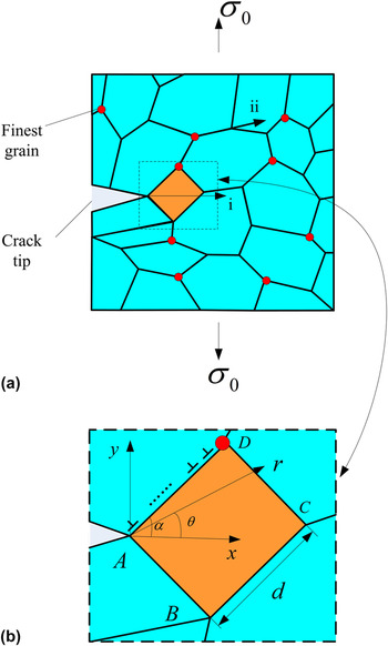
In general, there are two extended modes for the crack propagation in polycrystals: (i) crack crosses the grain (transgranular propagation); (ii) crack travels the interface region between the grains (intergranular propagation), as schematically shown in Fig. 1(a).
The grain boundary sliding deformation in a deformed NC solid materials containing a crack: (a) general view and (b) the general view inset highlighting the emission of edge dislocations from the crack tip A and pileup at the triple junction D due to the finest grain.

Actually, both of the two modes happen simultaneously. In our model, we focus on the intergranular propagation of crack in the NC materials with finest grains. Thus, we only consider a special case that crack tip is located on GBs. We assume an elastically isotropic NC material with the shear modulus G and Poisson's ratio ν. A long flat mode I crack with length l develops under the action of tensile load (external stress) σ0 [Fig. 1(a)]. Meanwhile, the crack growth direction is perpendicular to the tensile load direction. To highlight our theme, we restrict our consideration to a two-dimensional grain structure in which both the extended direction of the crack and grain structure stay within the same xy plane [shown in Fig. 1(b)].
High stress concentration near the crack tip can initiate the generation of edge dislocations and emitting along the GB. In the framework of our two-dimensional model, we assume that the crack tip reaches the junction of a quadrate grain boundary in which case the GB sliding occurs, as shown in Fig. 1(b). Furthermore, a finest grain is located at another junction near the quadrate grain [point D as shown in Fig. 1(b)]. When the stress intensity near the crack tip is large enough, edge dislocations can be generated at the crack tip and emitted along the GB. Since triple junctions serve as obstacles to dislocation slip, Reference Fedorov, Gutkin and Ovid'ko21,Reference Hu, Huo, Zhou, Wang and Zhang26,Reference Bobylev, Mukherjee, Ovid and Sheinerman30 the emitted GB dislocations are stopped at the triple junction D where a finest grain is located. The finest grain enhances the pile-up of the edge dislocations so that there may be multiple dislocations existing on the GB. Generally speaking, the first emitted dislocation is followed by the next along the GB AD and so on for each of the dislocations. Finally, all of the dislocations are at equilibrium status once the forces acting on them become balanced.
To explore the effects of finest grain on the GB sliding and fracture toughness of NC materials quantitatively, we introduce a Cartesian system (x, y) and a polar coordinate system (r, θ) with the origin at the crack tip [point A as shown in Fig. 1(b)]. The parameter α is denoted as the angle between the crack extending plane and the GB which the dislocations slide along. The GB arms are assumed to be equal to the grain size d and much smaller than the crack length l (d << l) so that this mode I crack becomes a semi-infinite crack.
III. CALCULATION
Within the macroscopic mechanical description, the effect of the local plastic flow (intergrain sliding resulting in the emitted dislocations and the pile-up of dislocations due to finest grain) on crack growth can be accounted for via introducing the standard crack growth criterion. The criterion is based on the balance between the driving force related to a decrease in the elastic energy and the hampering force related to occurrence of a new free surface during crack growth, Reference Bobylev, Mukherjee, Ovid and Sheinerman30 which can be given as
 $${{1 - {\rm{\nu }}} \over {2G}}\left( {K_{\rm{I}}^2 + K_{{\rm{II}}}^2} \right) = 2{{\rm{\gamma }}_{\rm{e}}}$$
where K I and K II are the intensity factors for normal (to crack line) and shear stresses, respectively; γe is the specific surface energy. In our model, the crack growth direction is perpendicular to the direction of the external load σ0, and the coefficients K I and K II are given as
 $${K_{\rm{I}}} = K_{\rm{I}}^{\rm{d}} + K_{\rm{I}}^{\rm{\sigma }}$$
 $${K_{{\rm{II}}}} = K_{{\rm{II}}}^{\rm{d}}$$
Here,
 $K_{\rm{I}}^{\rm{\sigma }}$
,
 $K_i^{\rm{d}}$
(i = I, II) are denoted as the intensity factors for the external stress σ0 and the stresses created by the edge dislocations located near the crack tip, respectively.
To study the effect of the pile-up dislocations on the fracture toughness of NC materials due to the finest grains, we introduce the critical stress intensity factor
 $K_{{\rm{IC}}}^*$
. The crack is assumed to keep propagating under the action of the tensile load perpendicular to the crack growth direction, in which case,
 $K_{\rm{I}}^{\rm{\sigma }} = K_{{\rm{IC}}}^*$
.
Reference Bobylev, Mukherjee, Ovid and Sheinerman30
From formula (1), the critical stress intensity factor
 $K_{{\rm{IC}}}^*$
can be represented as
 $$K_{{\rm{IC}}}^ * = \sqrt {{{\left( {K_{{\rm{IC}}}^{\rm{\sigma }}} \right)}^2} - {{\left( {K_{{\rm{II}}}^{\rm{d}}} \right)}^2}} - K_{\rm{I}}^{\rm{d}}$$
where
 $K_{{\rm{IC}}}^{\rm{\sigma }} = \sqrt {{{4G{\rm{\gamma }}_{\rm{e}} } \mathord{\left/ {\vphantom {{4G{\rm{\gamma }}_{\rm{e}} } {\left( {1 - {\rm{\nu }}} \right)}}} \right. \kern-\nulldelimiterspace} {\left( {1 - {\rm{\nu }}} \right)}}}$
is the fracture toughness in the case not considered the effect of dislocations, that is, the case of the pile-up dislocations being completely suppressed.
In our model, there may be n (n ≥ 1) dislocations pile-up along the GB because of the existence of finest grains. According to Ref. Reference Ovid’ko and Sheinerman18, formula (3) turns to be
 $$K_{{\rm{IC}}}^ * = \sqrt {{{\left( {K_{{\rm{IC}}}^{\rm{\sigma }}} \right)}^2} - {{\left( \,{\mathop\sum\limits_{i = 1}^n {K_{{\rm{II}}}^{\rm{d}}\left( {{r_i},{\rm{\theta }}} \right)} } \right)}^2}} - {\mathop\sum\limits_{i = 1}^n {K_{\rm{I}}^{\rm{d}}\left( {{r_i},{\rm{\theta }}} \right)}$$
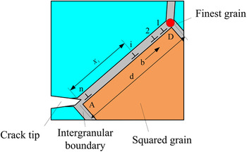
where r i is the distance between the crack tip and the balance position of the ith dislocations (shown in Fig. 2); n is the number of pile-up dislocations.
Grain boundary dislocations slide along the GB AD. Due to the stress concentration at crack tip A, dislocations are nucleated and emitted from A, slide along the GB AD, and at last are stopped at triple junction D where a finest grain is located. The emission of the first dislocation is followed by the emission of the next dislocations along GB AD and finally all of the dislocations are at equilibrium status once the forces acting on them become balanced.

Now the critical stress intensity factor
 $K_{{\rm{IC}}}^*$
for the case where the pile-up of dislocations occurs will be calculated. From formula (4), the values of parameters
 $K_{\rm{I}}^{\rm{d}}\left( {{r_i},{\rm{\theta }}} \right)$
,
 $K_{{\rm{II}}}^{\rm{d}}\left( {{r_i},{\rm{\theta }}} \right)$
, and n have to be calculated first.
The stress intensity factors
 $K_{\rm{I}}^{\rm{d}}\left( {{r_i},{\rm{\theta }}} \right)$
and
 $K_{{\rm{II}}}^{\rm{d}}\left( {{r_i},{\rm{\theta }}} \right)$
for the stress created by the edge dislocations are calculated using the formula proposed by Li et al.
Reference Li and Ebrahimi31
 $$K_{\rm{I}}^{\rm{d}}\left( {{r_i},{\rm{\theta }}} \right) = - {{3{\rm{\pi }}Db\,\sin \,{\rm{\theta }}\,\cos \left( {{{\rm{\theta }} \mathord{\left/ {\vphantom {{\rm{\theta }} 2}} \right. \kern-\nulldelimiterspace} 2}} \right)} \over {\sqrt {2{\rm{\pi }}{r_i}} }}$$
 $$K_{{\rm{II}}}^{\rm{d}}\left( {{r_i},{\rm{\theta }}} \right) = - {{3{\rm{\pi }}Db\left[ {\cos \left( {{{\rm{\theta }} \mathord{\left/ {\vphantom {{\rm{\theta }} 2}} \right. \kern-\nulldelimiterspace} 2}} \right) + 3\cos \left( {{{3{\rm{\theta }}} \mathord{\left/ {\vphantom {{3{\rm{\theta }}} 2}} \right. \kern-\nulldelimiterspace} 2}} \right)} \right]} \over {2\sqrt {2{\rm{\pi }}{r_i}} }}$$
where D = G/[2π(1 − ν)] and b represents the Burgers vector magnitude of GB dislocations.
From formulas (4) and (5), we know that the value of
 $K_{{\rm{IC}}}^*$
depends on Burgers vector magnitude b and dislocations number n.
Bobylev et al. Reference Bobylev, Mukherjee and Ovid’ko32 pointed out that the Burgers vectors of the dislocations in amorphous GBs are not lattice vectors, because the GB dislocations result from gradual accumulation of local shear events within the amorphous interpartial boundaries. The magnitude of the shear gradually increases in parallel with the number of the local shear events. Hence, in our model, the Burgers vector magnitude b is arbitrary. This assumption has been used in many existing papers. Reference Liu, Zhou, Shen and Hui27,Reference Bobylev, Mukherjee, Ovid and Sheinerman30 The dislocation Burgers vector magnitude b which changes with the shear stress created by GB sliding corresponds to the minimum of the energy change ΔW associated with the dislocation generation process. Reference Liu, Zhou, Shen and Hui27 Bobylev et al. Reference Bobylev, Mukherjee, Ovid and Sheinerman30 considered the energy change ΔW as only one dislocation existing on the GB, but in our model, there should be more dislocations pile-up during the GB sliding due to the existence of finest grain. The energy change ΔW can be calculated as follows
 $${\rm{\Delta }}W = {\mathop\sum\limits_{i = 1}^n {W_i^{\rm{e}}} + n \times {W^{\rm{c}}} - E$$
where
 $W_i^{\rm{e}}$
denotes the proper elastic energy of the ith dislocation; W
c is the dislocation core energy, and E is the energy used to generate the dislocations.
The proper elastic energy
 $W_i^{\rm{e}}$
of the ith dislocation can be written as
 $$W_i^{\rm{e}} \approx {{D{b^2}} \over 2}{\rm{ln}}{{{r_i}} \over {{r_{\rm{c}}}}}$$
Here r
c denotes the dislocation core radius and can be taken as 0.1 nm for all the materials.
Reference Bobylev, Mukherjee, Ovid and Sheinerman30
Furthermore, in the same material, the proper elastic energy
 $W_i^{\rm{e}}$
depends on the distance r
i
. The dislocation core energy W
c in the standard approximation is given as
Reference Hirth and Lothe33
:
 $${W^{\rm{c}}} \approx {{D{b^2}} \over 2}$$
The energy E used to generate the dislocations can be obtained via studying the work W done by the force
 $F_i^{\rm{c}}$
(i = 1, 2, …, n) which is created due to the crack extension and aimed to emit the dislocations. The force
 $F_i^{\rm{c}}$
acts on the dislocations so that
 $F_i^{\rm{c}}$
and E can be defined as
 $F_i^{\rm{c}} = b{\rm{\sigma }}_i^{\rm{F}}$
and E = W, respectively. The stress
 ${\rm{\sigma }}_i^{\rm{F}}$
represents the stress created by the crack tip. From Fig. 2, we get
 $$W = \mathop\sum\limits_{i = 1}^n {\left( {F_i^{\rm{c}} - b{{\rm{\tau }}_0}} \right){X_i}} = b\mathop\sum\limits_{i = 1}^n {\int {{\rm{\sigma }}_i^{\rm{F}}{\mathop{\rm d}\nolimits} {r_i}} } - b\mathop\sum\limits_{i = 1}^n {{{\rm{\tau }}_0}{r_i}}$$
where τ0 is the stress corresponding to the friction force which acts on the moving dislocation and is numerically equal to bτ0. Reference Bobylev, Mukherjee, Ovid and Sheinerman30 As can be seen in the formulas mentioned above, the value of the threshold shear stress τ0 for the intergrain sliding is commonly very low. For instance, in the case of Al, the stress does not exceed 4 MPa. Reference Du, Bower, Krajewski and Taleff34 In these circumstances, it is a good approximation to take τ0 = 0, for both Al and Ni.
Dislocation positions r i can be calculated effectively as the roots of the first derivatives of the corresponding Laguerre polynomial. Reference Eshelby, Frank and Nabarro35
The Laguerre polynomial L n (x) is defined as the solution of the following equation:
 $${x^2}{{{{\mathop{\rm d}\nolimits} ^2}y} \over {{\mathop{\rm d}\nolimits} {x^2}}} + (1 - x){{{\mathop{\rm d}\nolimits} y} \over {{\mathop{\rm d}\nolimits} x}} + ny = 0$$
The first derivative
 $L_n^\prime \left( x \right)$
of the Laguerre polynomial is the solution of the equation:
 $$x{{{{\mathop{\rm d}\nolimits} ^2}y} \over {{\mathop{\rm d}\nolimits} {x^2}}} + (2 - x){{{\mathop{\rm d}\nolimits} y} \over {{\mathop{\rm d}\nolimits} x}} + (n - 1)y = 0$$
 $L_n^\prime \left( x \right)$
can be written as follows:
 $$L_n^\prime (x) = - \mathop\sum\limits_{k = 0}^{n - 1} {{{n!{{( - x)}^k}} \over {k!(k + 1)!(n - k - 1)!}}}$$
The roots of the
 $L_n^\prime \left( x \right)$
coincide with dislocation positions in a discrete pile-up.
Reference Eshelby, Frank and Nabarro35
In the framework of this model, the crack extends along the GBs so that we assume that the dislocations are emitted due to highly localized stress concentration near the crack tip and travel along the GBs. From Fig. 2, the ith dislocation emitted from the crack tip reaches its equilibrium position when the total stresses
 ${\rm{\sigma }}_i^{{\rm{tot}}}$
acting on the ith dislocation turn to be zero (
 ${\rm{\sigma }}_i^{{\rm{tot}}} = 0$
).
 $${\rm{\sigma }}_i^{\rm{F}}\left( {{r_i},{\rm{\theta }}} \right) + {\rm{\sigma }}_i^{{\rm{im}}}\left( {{r_i},{\rm{\theta }}} \right) + \mathop\sum\limits_{\scriptstyle i = 1 \hfill \atop \scriptstyle j \ne i \hfill} ^n {{\rm{\sigma }}_{ij}^{\rm{d}}} \left( {{r_i},{\rm{\theta }}} \right) = 0$$
Here
 ${\rm{\sigma }}_i^{\rm{F}}\left( {{r_i},{\rm{\theta }}} \right)$
is the stress created by the applied load near the crack tip and corresponds to the force induced by the applied load σ0 on the ith dislocation;
 ${\rm{\sigma }}_i^{{\rm{im}}}\left( {{r_i},{\rm{\theta }}} \right)$
is the stress created by the crack free surface and aimed to attract the dislocation not to be emitted from the crack tip;
 ${\rm{\sigma }}_{ij}^{\rm{d}}\left( {{r_i},{\rm{\theta }}} \right)$
is the stress induced by the jth dislocation and corresponds to the force applied on the ith dislocation.
The stress
 ${\rm{\sigma }}_i^{\rm{F}}\left( {{r_i},{\rm{\theta }}} \right)$
can be calculated via the theory of Lin and Thomson
Reference Lin and Thomson36
:
 $${\rm{\sigma }}_i^{\rm{F}}\left( {{r_i},{\rm{\theta }}} \right) = {{K_{\rm{I}}^{\rm{\sigma }}\sin {\rm{\theta }}\cos \left( {{\rm{\theta }}/2} \right)} \over {2\sqrt {2{\rm{\pi }}{r_i}} }}$$
The image stress
 ${\rm{\sigma }}_i^{{\rm{im}}}\left( {{r_i}} \right)$
that corresponds to the force of the interaction between the ith dislocation and the crack free surface is given as:
 $${\rm{\sigma }}_i^{{\rm{im}}}\left( {{r_i}} \right) = - {{Gb} \over {4{\rm{\pi }}\left( {1 - {\rm{\nu }}} \right){r_i}}}$$
The stress
 ${\rm{\sigma }}_i^{\rm{F}}\left( {{r_i},{\rm{\theta }}} \right)$
corresponding to the force induced by the applied load σ0 on the ith dislocation depends on the distance r
i
between the ith dislocation and crack tip. So the work W done by the force
 $F_i^{\rm{c}}$
can be written as
 $$W = b\mathop\sum\limits_{i = 1}^n {\int {{\rm{\sigma }}_i^{\rm{F}}\left( {{r_i},{\rm{\theta }}} \right){\mathop{\rm d}\nolimits} {r_i}} }$$
Now the maximum number n of the dislocations existing on the GB AD will be calculated. First, we consider the total stresses
 ${\rm{\sigma }}_1^{{\rm{tot}}}$
acting on the first emitted dislocation. Following the theory of Rice–Thompson,
Reference Rice and Thomson37
it can be assumed that the first dislocation is emitted if this dislocation is repelled from the crack tip exceeds the dislocation core radius r
0. So the critical condition for the emission of the first dislocation can be written as follows:
 $${\rm{\sigma }}_1^{\rm{F}}\left( {{r_1},{\rm{\theta }}} \right) + {\rm{\sigma }}_1^{{\rm{im}}}\left( {{r_1},{\rm{\theta }}} \right) > 0$$
The first GB dislocation is generated from the crack tip A and emitted along the boundary AD and then stopped at triple junction D due to the existence of finest grain (shown in Fig. 2). At this time, the triple junction with a finest grain can be considered as a strong obstacle for GB dislocations sliding Reference Liu, Zhou, Shen and Hui27 so that GB dislocations need much more energy to slide through the triple junction than the normal triple junction. For simplicity, the finest grain is taken as a part of triple junction without the consideration of the GB sliding at finest grain. In the case of the first dislocation emitted from the crack tip and stopped at the triple junction with a finest grain, we get
 $${\rm{\sigma }}_1^{\rm{F}}\left( {{r_1},{\rm{\theta }}} \right) + {\rm{\sigma }}_1^{{\rm{im}}}\left( {{r_1},{\rm{\theta }}} \right) - {{\rm{\tau }}^{\rm{u}}}\,{\rm{ = }}\,\,0$$
where τu is the shear stress created by the finest grain and corresponds to the force against the movement of the first dislocation.
 $${\rm{\sigma }}_1^{\rm{F}}\left( {{r_1},{\rm{\theta }}} \right)\,{\rm{ =\, }}{{K_{\rm{I}}^{\rm{\sigma }}\sin {\rm{\theta }}\,\cos \left( {{\rm{\theta }}/2} \right)} \over {2\sqrt {2{\rm{\pi }}{r_1}} }}$$
 $${\rm{\sigma }}_1^{{\rm{im}}}\left( {{r_1},{\rm{\theta }}} \right) = - {{Gb} \over {4{\rm{\pi }}\left( {1 - {\rm{\nu }}} \right){r_1}}}$$
If the first dislocation moves far enough from the crack tip, the crack tip attraction zone is slightly increased for the second emitted dislocation. In this case, the second dislocation can overcome the image force and be emitted till its equilibrium position. The following emitted dislocations are as the same as the second dislocation. As a result, the critical condition for the emission of the jth dislocation (j = 2, 3, …, n) turns to be
 $${\rm{\sigma }}_j^{\rm{F}}\left( {{r_j},{\rm{\theta }}} \right) + {\rm{\sigma }}_j^{{\rm{im}}}\left( {{r_j},{\rm{\theta }}} \right) + \mathop\sum\limits_{\scriptstyle i = 1 \hfill \atop \scriptstyle j \ne i \hfill} ^n {{\rm{\sigma }}_{ij}^{\rm{d}}} \left( {{r_i},{r_j},{\rm{\theta }}} \right) > 0$$
For the first dislocation, the total stress created by other (n − 1) dislocations and acting on the first dislocation growth gradually with the number of dislocations increases. In other words, the shear stress τu increases gradually. According to the study of Liu, Reference Liu, Zhou, Shen and Hui27 however, the first dislocation stopped at triple junction will across the finest grain via slipping into an immobile edge dislocation and a mobile partial edge dislocation when the shear stress τu reaches a critical value τc. That means, if the number of the pile-up dislocations along the GB reaches the capacity, the following condition should be satisfied simultaneously:
 $${\rm{\sigma }}_1^{\rm{F}}\left( {{r_1},{\rm{\theta }}} \right) + {\rm{\sigma }}_1^{{\rm{im}}}\left( {{r_1},{\rm{\theta }}} \right)\,{\rm{ + }}\mathop\sum\limits_{j = 2}^n {{\rm{\sigma }}_{1j}^{\rm{d}}\left( {{r_1},{r_j},{\rm{\theta }}} \right)} \,\le\, {{\rm{\tau }}^{\rm{c}}}$$
According to the proposed model of Asaro, Krysl, and Kad (AKK) Reference Asaro, Krysl and Kad17 for the emission of partial dislocations, the critical value of the shear stress τc is given as
 $${{{{\rm{\tau }}^{\rm{c}}}} \over G} \approx {1 \over 3}{b \over {{d^{\rm{u}}}}} + {{{\rm{\alpha }} - 1} \over {\rm{\alpha }}}{{\rm{\Gamma }} \over {Gb}}$$
 $${\rm{\alpha }}\, \equiv\, {{{d^{\rm{u}}}} \mathord{\left/ {\vphantom {{{d^{\rm{u}}}} {{{\rm{\delta }}_{{\rm{eq}}}}}}} \right. \kern-\nulldelimiterspace} {{{\rm{\delta }}_{{\rm{eq}}}}}}$$
where Γ denotes the stacking-fault energy, d u is the finest nanograin size, and δeq denotes the minimum equilibrium spacing. From Han et al., Reference Han, Zhang, Wu and Li38 we get the following expression:
 $${{\rm{\delta }}_{{\rm{eq}}}} = {1 \over {12{\rm{\pi }}}}{{G{b^2}} \over {\rm{\Gamma }}}$$
where Γ/Gb = 1/250 for Cu and Γ/Gb = 1/100 for Ni.
Every dislocation existing on the GB will create a stress field and act on other dislocations. The repulsive forces
 $F_{ij}^{\rm{d}}$
between ith dislocation and jth dislocation depend only on their relative spacing
Reference Hu, Huo, Zhou, Wang and Zhang26
:
 $$F_{ij}^{\rm{d}}\left( {{r_i},{r_j},{\rm{\theta }}} \right) = {{G{b^2}} \over {2{\rm{\pi }}\left( {1 - {\rm{\nu }}} \right)}}{1 \over {{r_i} - {r_j}}}$$
So the total stress created by other (n − 1) dislocations acting on the first dislocation can be written as
 $$\mathop\sum\limits_{j = 2}^n {{\rm{\sigma }}_{1j}^{\rm{d}}} \left( {{r_1},{r_j},{\rm{\theta }}} \right){\rm{ \,=\, }}{{Gb} \over {2{\rm{\pi }}\left( {1 - {\rm{\nu }}} \right)}}\mathop\sum\limits_{j = 2}^n {{1 \over {{r_1} - {r_j}}}}$$
Following formulas (17)–(27), the number n of the GB dislocations that emitted from crack tip to the triple junction containing a finest grain can be calculated by iteration method. First, the validity of formula (17) for emitting the first dislocation is checked. If this criterion is valid, the first dislocation is emitted to the triple junction D (shown in Fig. 2) and the validity of formulas (21) and (22) for emitting the second dislocation is checked simultaneously. If these two criterions are valid at the same time, the equilibrium position of the second dislocation is studied and the validity of criterions (21) and (22) is checked for emitting the third dislocation, and so on. The procedure is carried out for all the new emitted dislocations and ends once one of the criterions (21) and (22) stops to be valid.
The Burgers vector magnitude b of final equilibrium dislocations corresponds to the minimum of the energy changes ΔW and follows the relationship
 $${{\partial \Delta W} \over {\partial b}} = 0$$
Formulas (6)–(28) allow the Burgers vector magnitude b of final equilibrium dislocations to be calculated.
 $$b = {{K_{\rm{I}}^{\rm{\sigma }}\sin {\rm{\theta }}\,\cos \left( {{\rm{\theta }}/2} \right)\mathop\sum\limits_{i = 1}^n {\sqrt {{r_i}} } } \over {D\sqrt {2{\rm{\pi }}} \mathop\sum\limits_{i = 1}^n {\left[ {{\rm{ln}}\left( {r_i^2/{r_{\rm{c}}}} \right) + 1} \right]} }}$$
To sum up, the effect of GB sliding mechanism on the fracture toughness of NC materials with finest grains has been studied. The Burgers vector magnitude b of the edge dislocations and the maximal number n of the pile-up dislocations due to the existence of the finest grain during the GB sliding process can be calculated by formulas (6)–(9) and formulas (13)–(29), separately. The distance r
i
between the equilibrium position of ith dislocations and the crack tip is calculated quantitatively via Laguerre polynomial [Formulas (10)–(12)]. Finally, the critical stress intensity factor
 $K_{{\rm{IC}}}^*$
is calculated by formulas (1)–(5) in the case that GB sliding mechanism plays the dominating role during the plastic deformation process of the NC materials.
IV. RESULT AND DISCUSSION
To characterize the change of the fracture toughness, the critical stress intensity factor
 $K_{{\rm{IC}}}^*$
should be compared with the fracture toughness
 $K_{{\rm{IC}}}^{\rm{\sigma }} = \sqrt {{{4G{\rm{\gamma }}_{\rm{e}} } \mathord{\left/ {\vphantom {{4G{\rm{\gamma }}_{\rm{e}} } {\left( {1 - {\rm{\nu }}} \right)}}} \right. \kern-\nulldelimiterspace} {\left( {1 - {\rm{\nu }}} \right)}}}$
without the consideration of the effect of GB sliding.
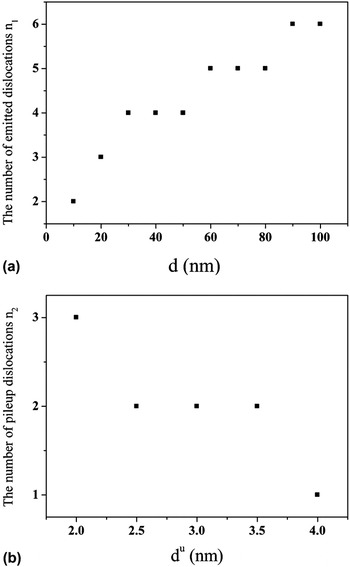
By calculating the maximum number n of the pile-up dislocations, as we can see from Fig. 3, the number n is determined by both the capacity of dislocations emitting associated with the crack propagation and the capacity of dislocations pile-up due to the existence of the finest grains. The number n 1 denotes the emissive capacity of dislocations at crack tip and n 2 represents the pile-up capacity at the triple junction, the maximum number n of the dislocations sliding along the GB can be written as
 $$n = \min \left( {{n_1},{n_2}} \right)$$
(a) The dependence of the number n 1 of the emitted dislocations at crack tip on the average grain size d; (b) the dependence of the number n 2 of the pileup dislocations at triple junction on the finest grain size d u.

The calculation of the parameters n 1 for different average grain sizes d and n 2 for different finest grain sizes d u (between 2–4 nm) indicates that the maximal number n of the pile-up dislocations increases with increment of the grain size d and decrement of the finest grain size d u. For example, if the finest grains maintain 2 nm and α = 70°, there will be three edge dislocations pile-up on GB when the quadrate grain size d is larger than 23 nm while there only being two dislocations if d turns to below 23 nm (Fig. 3). It is worth noting that when the grain size increases over 23 nm, there will not be more dislocations pile-up and maintains three dislocations on the GB. Since the finest grain size is a constant, the pile-up capacity remains unchanged and finest grain cannot stop more dislocations even when the emissive capacity is enhanced during grain size increasing. That means n is subject to the pile-up capacity due to the existence of the finest grains when the average grain size d is large enough. On the other hand, when the grain size decreases to a critical size (23 nm in our model), the number n of edge dislocations is mainly subject to the emissive capacity rather than the pile-up capacity.
Figure 4 shows the dependence of the ratio
 ${{K_{{\rm{IC}}}^* } \mathord{\left/ {\vphantom {{K_{{\rm{IC}}}^* } {K_{{\rm{IC}}}^{\rm{\sigma }} }}} \right. \kern-\nulldelimiterspace} {K_{{\rm{IC}}}^{\rm{\sigma }} }}$
on the angle α between the crack extending plane and the GB which the dislocations slide along in NC Ni with finest grains and without finest grains, separately. The typical values of parameters of NC Ni are as follows: G = 73 GPa, ν = 0.31, γ = 1.725 J m−2. It can be seen that the effective fracture toughness
 $K_{{\rm{IC}}}^*$
increases for the angle α ≤ 70° and decreases for 70° < α ≤ 90° when the finest grain is located at the triple junction. Accordingly, the critical fracture toughness
 $K_{{\rm{IC}}}^*$
reaches its maximal value for α = 70°. This coincides with the fact that the stress σF reaches its maximum when the plane makes the angle ≈70° with the direction of crack extend. At this time, the fracture toughness of NC materials with finest grains is increased by 50% than the normal triple junctions. It is also found that the existence of finest grain can significantly improve the fracture toughness of NC materials without compromising the trend associated with the angle α.
The dependence of the ratio
 ${{K_{{\rm{IC}}}^* } \mathord{\left/ {\vphantom {{K_{{\rm{IC}}}^* } {K_{{\rm{IC}}}^{\rm{\sigma }} }}} \right. \kern-\nulldelimiterspace} {K_{{\rm{IC}}}^{\rm{\sigma }} }}$
on the angle α, for d = 50 nm.

Figure 5 shows the dependence of the ratio
 ${{K_{{\rm{IC}}}^* } \mathord{\left/ {\vphantom {{K_{{\rm{IC}}}^* } {K_{{\rm{IC}}}^{\rm{\sigma }} }}} \right. \kern-\nulldelimiterspace} {K_{{\rm{IC}}}^{\rm{\sigma }} }}$
on the grain size d for α = 70° in NC Ni with a finest grain and without finest grain, separately. It depicts that the fracture toughness roughly decreases with the increment of the average grain size d and the critical fracture toughness
 $K_{{\rm{IC}}}^*$
of the NC Ni with finest grains is increased by 40–100% than the normal NC Ni metal. In the NC Ni with finest grains, the average grain size d ≈ 23 nm is a critical size. When the quadrate grain size d is larger than 23 nm, there are three edge dislocations pile-up on the GB and in the case of d < 23 nm, there are only two dislocations. When the grain size d increases over the critical size 23 nm, the number n of the edge dislocations turns from two into three, which explains well that why there is a faster growing trend at around 23 nm. Considering that GB is too short to pile-up dislocations when d reduced to below 10 nm, the situation of d < 10 nm is not included in our research.
The dependence of the ratio
 ${{K_{{\rm{IC}}}^* } \mathord{\left/ {\vphantom {{K_{{\rm{IC}}}^* } {K_{{\rm{IC}}}^{\rm{\sigma }} }}} \right. \kern-\nulldelimiterspace} {K_{{\rm{IC}}}^{\rm{\sigma }} }}$
on grain size d, for α = 70°, d
u = 2 nm.

V. CONCLUSION
A theoretical model has been developed to study the critical stress intensity factor
 $K_{{\rm{IC}}}^*$
of NC materials which characterizes fracture toughness in the case that finest grains are located at the triple junctions. The process of crack blunting and propagation is simultaneously controlled by the emission of dislocations from the crack tip and pile-up of dislocations at the triple junctions with a finest grain. To characterize the effects of finest grain on crack growth and fracture toughness, the critical stress intensity factor
 $K_{{\rm{IC}}}^*$
is compared with the stress intensity factor
 $K_{{\rm{IC}}} = \sqrt {{{4G{\rm{\gamma }}} \mathord{\left/ {\vphantom {{4G{\rm{\gamma }}} {\left( {1 - {\rm{\nu }}} \right)}}} \right. \kern-\nulldelimiterspace} {\left( {1 - {\rm{\nu }}} \right)}}}$
in the dislocation-free case. The calculation indicates that the existence of finest grains can significantly enhance the fracture toughness of NC materials. For instance, the fracture toughness can increase by 60% with the introduction of finest grains. In addition, the toughening effect of the finest grains is sensitive to the grain size. For example, Fig. 5 shows the increment of the nanograin size from 10 to 100 nm decreases
 ${{K_{{\rm{IC}}}^* } \mathord{\left/ {\vphantom {{K_{{\rm{IC}}}^* } {K_{{\rm{IC}}}^{\rm{\sigma }} }}} \right. \kern-\nulldelimiterspace} {K_{{\rm{IC}}}^{\rm{\sigma }} }}$
by 50% and thus makes NC materials much more brittle. We also found that in the NC Ni with finest grains, the average grain size d ≈ 23 nm is a critical size that there are three edge dislocations pile-up on the GB when the grain size d is larger than 23 nm while there only being two dislocations if d turns to below 23 nm. When the grain size d increases over the critical size, the number n of the edge dislocations turns from two into three, which explains well the significant slowdown trend of fracture toughness.
ACKNOWLEDGMENTS
This work was supported by Key Project of Chinese Ministry of Education (211061), National Natural Science Foundation of China (10502025, 10872087, 11272143), and Program for Chinese New Century Excellent Talents in university (NCET-12-0712).