I. INTRODUCTION
With the rapid development of society and industrialization processes, the kinds and amount of organic pollutants in industrial effluents increase sharply, which causes a great challenge to the traditional water treatment process. Therefore, photocatalytic oxidation technology, as a very effective, nontoxic, energy-saving, nonsecondary pollution procedure for the degradation of a variety of organic contaminants, has drawn a considerable attention.Reference Rodriguez, Peche, Merino and Camarero1, Reference Fujihira, Satoh and Osa2 Nanocrystalline semiconductor TiO2, which is an abundant, nontoxic, chemically stable, effectual photocatalyst, has been found to have extensive applications to solve these environmental problems, such as decomposition of inorganic and organic pollutants and toxic material in both liquid and gas phase systems.Reference FuJishima and Honda3, Reference Bakardjieva, Šubrt, Štengl, Dianez and Sayagues4 However, only the ultraviolet light (λ < 387 nm), which occupies 4% of solar light energy, can be absorbed by pure anatase TiO2 to generate electron-hole pairs.Reference He, Liu, Sun, Yan, Zhang, Qi, Xu, Wu and Wei5 For this reason, the practical photocatalytic application of TiO2 is limited. On the other hand, the photogenerated electron-hole pairs, which play the most important role during the photodegradation process, are liable to recombine, thus leading to the low efficiency of photocatalyst.Reference Berger, Sterrer, Diwald, Knozinger, Panayotov, Thompson and Yates6, Reference Rupa, Manikandan, Divakar and Sivakumar7 Therefore, to enhance photocatalytic activity, it is paramount to extend the photoresponse of TiO2 to the visible region and to reduce the recombination of electron-hole pairs.
Recently, to overcome the deficiencies of TiO2 mentioned earlier and then to improve its photocatalysis performance, many works have been attempted. These works include doping TiO2 with noble metals such as Pt, Ag, AuReference Choi, Park and Hoffmann8–Reference Zhao, Sallard, Smarsly, Gross, Bertino, Boissiere, Chen and Shi10 and with nonmetals such as N, S, C etc.,Reference Simon, Pignon, Miao, Coste-Leconte, Leconte, Marguet, Jegou, Bouchet-Fabre, Reynaud and Herlin-Boime11–Reference Kang, Zhang, Yin, Sato and Saito13 and sensitizing TiO2 with dye molecules and other compounds.Reference Rego, da Silva, Freire, Snoeberger and Batista14, Reference Li, Wang, Shi and Zeng15 According to the literature, the modification of TiO2 by doping with no matter metal or nonmetal atoms is almost conducted by adding certain amount of dopants to the solution for preparation of TiO2. That is to say, the dopants are distributed not only on the particle surface but also within TiO2 crystals. However, as we all know, the photodegradation process takes place mostly on the surface of semiconductor photocatalyst because the electron-hole pairs are photogenerated by the direct irradiation of light. The interfacial electron transfer reaction of charge carriers on the surface of photocatalyst is prerequisite for a photodegradation reaction.Reference Tachikawa, Tojo, Kawai, Endo, Fujitsuka, Ohno, Nishijima, Miyamoto and Majima16 Therefore, the dopants inside TiO2 crystals are void for photodegradation. It is meaningful to develop a surface modification method for enhancing photocatalytic activity of catalysts.
Ruthenium and ruthenium dioxide (RuO2) have been considered as effective catalysts and bottom electrode materials.Reference Lin, Lo and Mou17–Reference Cataldi, De Benedetto and Bianchini20 Different methods have been carried out to modify ruthenium, ruthenium oxide, or their nanoparticles on the porous thin films, such as electrochemical deposition,Reference De Benedetto and Cataldi21, Reference Macherzynski, Milczarek, Mamykin, Romanyuk and Kasuya22 chemical reduction,Reference Lin, Lo and Mou17 Cu underpotential deposition,Reference Yoo and Park18 sputteringReference Yoon, Roh, Lee and Baik23, Reference Ye, Cui, Liu, Lim, Zhang and Sheu24, and metalorganic chemical vapor deposition.Reference Kawano, Kosuge, Oshima and Funakubo25 The simpler modification method is to dip the porous film in the ruthenium trichloride solution followed by the thermal oxidization process.Reference Hrapovic, Jerkiewicz, Elboujdaini, Ghali and Zheng26 However, it is difficult to control the distribution of the ruthenium oxide formed on the surface of pores by this simple method. Usually, the modified oxides aggregate to form some islands at different sizes and shapes. This makes trouble to study the properties due to the modification of metal oxide.
In this study, we developed an approach to modify homogenous RuO2 on the surface of nanoparticles inside TiO2 porous thin film by monolayer adsorption of Ru-contained dye and followed by sintering at 450 °C. As a comparison, TiO2 film with inhomogeneous modification of RuO2 was prepared by dropwise adding appropriate concentration of ruthenium trichloride trihydrate solution on the TiO2 porous thin film. To evaluate the effect of homogeneous modification on the photocatalytic activity of TiO2 porous thin film, both kinds of RuO2-modified films were used as the photocatalyst to degrade eosin Y.
II. EXPERIMENTAL SECTION
A. Preparation of porous TiO2 thin films
The TiO2 colloidal paste was prepared by the hydrothermal method according to the procedure in literature.Reference Yin, Tan, Zhang, Weng, Xiao, Zhou, Li and Lin27 Then the paste was spread onto fluorine-doped tin oxide (FTO) glass substrate (20 Ω/□; Hake New Energy Co., Ltd, Harbin, China) by the doctor-blade method. After drying in air at room temperature, the film was sintered at 450 °C for 30 min.
B. Modification of ruthenium oxide on the TiO2 nanoporous thin film
Two methods were used to modify ruthenium oxide on TiO2 nanoparticles. Adsorption of Ru-contained dye followed by sintering at 450 °C (hereafter, named as impregnation method) was described as following. The as-prepared TiO2 porous film was dipped into absolute ethanol solution containing 0.5-mM cis-di(thiocyanato)-N,N′-bis(2,2′-bipyridyl-4,4′-dicarboxylic acid) ruthenium(II) complex (N3; Solaronix, Aubonne, Switzerland) for 24 h. Then, the film was rinsed with ethanol and dried in air. After adsorption of dye, the thin film was sintered at 450 °C for 30 min to burn off organic matters of dye and oxidize the left ruthenium cations on the film. The modification amount can be easily adjusted by repeating the above procedure comprising adsorption and sintering processes. For comparison, dropping method was also used to modify TiO2 nanoporous film, where certain amount of ruthenium trichloride trihydrate solution was dropwise added on the surface of the as-prepared TiO2 film, and then, the film was sintered at 450 °C for 30 min.
C. Characterization of the films
The surface morphologies of TiO2 films with and without ruthenium oxide modification were observed on a scanning electron microscope (SEM; S-4300, Hitachi, Toronto, Ontario, Canada) operated at an acceleration voltage of 15 kV, equipped with an energy dispersive x-ray spectroscope (EDX). The crystallographic characterization of the film was determined on an x-ray diffractometer (D/max 2500; Riguku, The Woodlands, TX) by Cu Kα irradiation. To analyze binding energy of the samples, the x-ray photoelectron spectra (XPS) were recorded by an electron spectroscope for chemical analysis (ESCA) Microprobe system (LAB2201-XL, VG Scientific, London, UK) using a Mg Ka excitation source. The amount of dye loaded into the film was determined by completely dissolving a known area of the TiO2 film into a known volume of NaOH (pH=10.5) aqueous solution and measuring its optical absorbance at the absorption maximum of N3 dye with a spectrophotometer (UV3010; Hitachi, Tokyo, Japan).
Intensity-modulated photovoltage spectroscopy (IMVS) was performed on the dye-sensitized solar cells (DSSCs) based on the TiO2 porous thin film or the ruthenium oxide-modified TiO2 thin films. A light emitting diode (LED, 470 nm) was used as the light source. The light intensity was modulated with a sine-shaped voltage supplied by a 1255B frequency response analyzer (FRA; Solartron, Hampshire, UK) between 0.1 Hz and 10 kHz. The DC light generated by the LED, with the intensity up to 2 W m−2, was used as the superimposed constant illumination in the measurements. The amplitude and phase shift of the voltage response with respect to the modulation of the light intensity were measured with FRA. The FRA and data acquisition were controlled by a personal computer. IMVS complex plane plots were recorded for the DSSCs under open-circuit conditions. DSSC with a sandwich cell structure was fabricated with a dye-sensitized nanocrystalline TiO2 thin film together with a Pt counter electrode and electrolyte composed of 0.5M LiI, 0.05M I2, and 0.5M 4-tert-butylpyridine in 3-methoxypropionitrile. Dye sensitization was performed by immersing the resulting films in a 0.5-mM ethanol solution of N3 for 24 h. A Pt counter electrode was prepared by spreading a 5-mM H2PtCl6 aqueous solution on a FTO glass substrate, followed by heating at 390 °C for 15 min. For IMVS measurements, the light was directed on the Pt counter electrode of DSSC with active area of 0.20 cm2.
D. Photodegradation experiment
The photodegradation experiments of eosin Y (Kanto, Tokyo, Japan) were conducted in an open beaker with 100 mL capacity at room temperature, and the beaker was opened to air to ensure enough oxygen in the solution. The TiO2 film or ruthenium oxide-modified TiO2 film was laid at the bottom of the beaker, immersed by 15-mL aqueous solution containing eosin Y with the initial concentration of 36 μM, which was exposed to illumination of a 125-W high-pressure Hg lamp (λ > 320 nm). Before the irradiation, the solution with TiO2 film was placed in darkness to establish adsorption–desorption equilibrium. The concentration of dye after adsorption–desorption equilibrium was treated as C 0. The change in the concentration of dye based on C 0 was detected by measuring absorbance of the dye solution taken out regularly from the reactor beaker.
III. RESULTS AND DISCUSSION
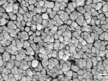
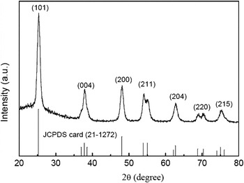
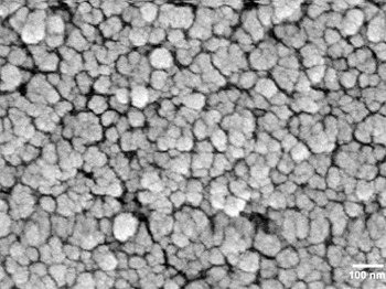
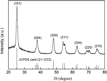
The SEM surface morphology of TiO2 thin film is shown in Fig. 1. We can observe spherical aggregates of nanoparticles (typically 40 nm in diameter) that are homogeneous in size and shape, to form a porous, high surface area film. The film thickness is about 4 μm. After modification of ruthenium cations, SEM image of the modified TiO2 thin films (not shown) does not illustrate any remarkable difference between them and the pure TiO2 film. EDX measurement accompanied with SEM observation determined Ru element amount of 0.62% (molar percentage) in the modified TiO2 thin film with four iterations of adsorption, which proves that ruthenium cations have been successfully modified on the porous TiO2 thin films. X-ray diffraction spectrum of the ruthenium oxide-modified TiO2 thin film shown in Fig. 2 indicates ruthenium cations modification does not affect the anatase crystalline structure of TiO2 film.
Morphology of the TiO2 nanoporous thin film by scanning electron microscope.
X-ray diffraction patterns of the ruthenium dioxide (RuO2)-modified TiO2 thin film with four times impregnation.
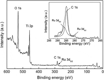
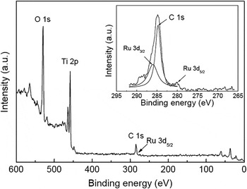
To distinguish the existing form of ruthenium cations after modification, we carried out XPS analysis, which is an important tool for examining surface electronic states of materials. In the XPS of ruthenium cation-modified TiO2 prepared by the impregnation method as shown in Fig. 3, the elements of Ti and O can be detected and their binding energies are 458.6 and 529.8 eV, respectively. The binding energy of Ru 3d3/2 is unfortunately overlaid with that of C 1s, thus its peak can not be clearly recognized. The peak corresponding to C 1s looks unsymmetrical and one peak at 286.0 eV can be separated from it. The separated peak is identified as Ru 3d3/2. At the same time, the binding energy of 280.1 eV is assigned to Ru 3d5/2. All of these results indicate the existing form of ruthenium cation is Ru4+, and it exists as RuO2 on the surface of TiO2 nanoparticles. The same measurements and analyses were conducted on the ruthenium cation-modified TiO2 prepared by the dipping method indicating ruthenium cation also exists as Ru4+ on the film.
Wide-scan x-ray photoelectron spectrum of the RuO2-modified TiO2 thin film with four times impregnation and its Ru 3d spectrum (inset).
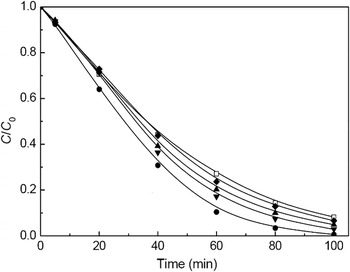
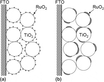
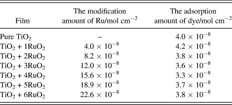
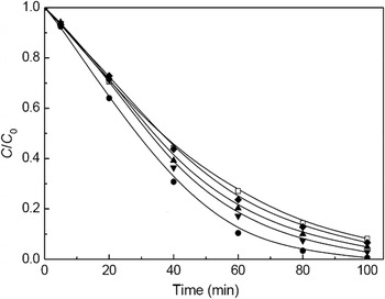
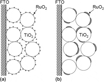
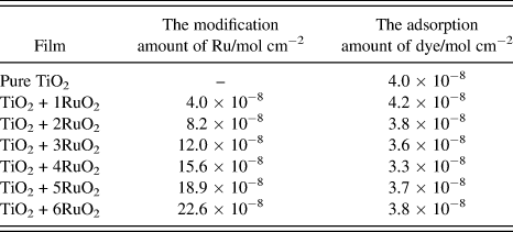
The large surface area of porous film is favorable for the adsorption of pollutant, which is recognized as the prerequisite procedure for photodegradation. However, at the same time, the large surface area makes more opportunities for the recombination of electron and hole, which will decrease the photocatalytic activity. The RuO2-modified TiO2 thin films prepared by the impregnation method and the dropping method were used as photocatalysts to degrade eosin Y in aqueous solution at room temperature. Before degradation, the blank experiment without photocatalyst was carried out to check the stability of eosin Y under irradiation of high-pressure Hg lamp. Without TiO2 film, the irradiated solution showed about 15% of self-degradation within 60 min for eosin Y. This value was used to correct the following photodegradation results of TiO2 films. Figure 4 shows the photocatalytic degradation curves of the left dye concentration as a function of irradiation time for the pure TiO2 thin film and RuO2-modified TiO2 thin films with different modification amounts prepared by different methods. The loaded amount of RuO2 can be controlled by the iteration numbers of adsorption and sintering processes. The adsorption amount of dye and the modification amount of RuO2 on porous TiO2 thin film were measured after each iteration and are listed in Table I. The modification amount of RuO2 almost increases linearly with the times of adsorption. This means modification of RuO2 does not affect readsorption of dye on the porous film. As a pure TiO2 film was used as a photocatalyst, within 60 min, 73% of eosin Y was degraded. For a porous TiO2 film with one time modification of RuO2, the degradation percentage is 80% within 60 min, whereas for a porous TiO2 film with four times modification, 90% of eosin Y was degraded. All of RuO2-modified TiO2 films show obviously higher degradation efficiency than the pure TiO2 thin film, indicating RuO2 modification increases photocatalytic efficiency of the TiO2 thin film. With increasing in the iterations of modification, the highest degradation efficiency occurs for the RuO2-modified TiO2 thin film with four times impregnation, where almost all of eosin Y was degraded after 100 min irradiation. The over-modification of RuO2 (six times impregnation), however, decreases the degradation efficiency. There is an adequate modification amount for the impregnation method. For comparison, the RuO2-modified TiO2 thin film with same amount of RuO2 as that of film with four times impregnation was prepared by the dropping method. Its photocatalytic performance is obviously worse than that of the film with same modification amount but prepared by the impregnation method and just a little better than that of the pure TiO2 thin film (Fig. 4). The difference between two kinds of modified films prepared by different methods is the distribution of RuO2 on the surface of TiO2 nanoparticle as shown in Fig. 5. The impregnation method leads to a homogenous distribution of RuO2 on the particles and in the porous film, while RuO2 will aggregate on the surface of TiO2 particle for the dropping method.
The photocatalytic degradation of eosin Y by the pure TiO2 film (□), the RuO2-modified TiO2 thin films prepared by the dropping method (♦) and by the impregnation method with twice dye adsorption (▲), four times dye adsorption (●), and six times dye adsorption (▼).
Schematic of RuO2-modified TiO2 porous thin films prepared by (a) the impregnation method and (b) the dropping method.
The adsorption amount of dye and the modification amount of Ru cations on the pure TiO2 and the ruthenium dioxide (RuO2)-modified TiO2 thin films (TiO2 + xRuO2, x represents the iteration numbers of impregnation).
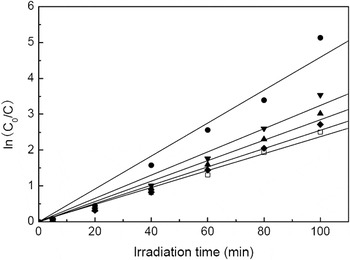
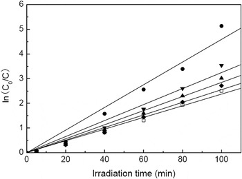
As already pointed out in literatures,Reference Li, Zhang, Guo, Han, Zhao, Zhao and Kim28, Reference Li, Wang, Cheng, Luo, An and Wang29 photocatalytic degradation reaction of organic pollutants usually follows the first-order kinetics. The kinetics of photodegradation reaction can be described by the Langmuir–Hinshelwood model by which the apparent rate constant can be determined. Figure 6 shows the linear relationship of ln(C 0/C) and irradiation time for the photocatalytic results shown in Fig. 4. The good linear relationship confirmed that the photodegradation process for all of catalysts follows the first-order kinetics. The photodegradation apparent rate constant is enhanced with increasing in the modification amount on the porous films, and attaches a maximum for the film with four times modification, then decreases after over loading of RuO2. For the different modification methods, under the same loading amount, homogeneous modification based on the impregnation method exhibits higher degradation apparent rate constant than the inhomogeneous modification based on the dropping method.
Relationship between irradiation time and ln(C 0/C) of photocatalytic degradation data shown in Fig. 4.
The basic degradation mechanism is usually explained as follows according to literatures.Reference Li, Wang, Cheng, Luo, An and Wang29, Reference Chiou, Wu and Juang30 Electron-hole pairs, generated by irradiating TiO2 nanoparticles, transfer to the surface of particles. After separated with electron, hole reacts with water to produce hydroxyl and superoxide radicals. These radicals can initiate a series of chemical reactions and act as a strong oxidizing agent to mineralize the pollutants. Therefore, the effective separation and the low recombination of electron-hole pairs are very important to decide the photodegradation efficiency. Adequate RuO2 homogenously distributed on the surface of TiO2 particles can serve as a shallow trap of holes to favor the separation of electron-hole pairs and retard the recombination of holes with electrons, thus improving photodegradation activity.Reference Ibhadon, Greenway and Yue31, Reference Einaga, Ibusuki and Futamura32
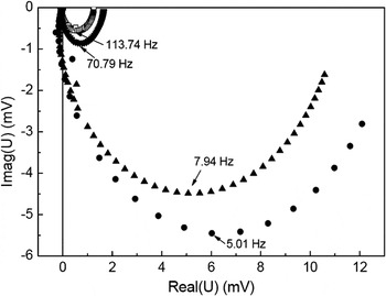
IMVS recorded the photovoltage response of electrode under the light modulated by a low intensity sine signal. As the IMVS measurement enables to distinguish the photovoltages under different modulating frequencies, the interfacial processes at different rates between electrode and electrolyte can be determined. IMVS is a useful method to study lifetime of electrons, which relates to the electron recombination process. To demonstrate the effect of RuO2 on this recombination in TiO2 porous thin film, IMVS of pure TiO2 and RuO2-modified TiO2 thin films was measured on the mode of DSSC fabricated by the dye-sensitized porous nanocrystalline film and platinized FTO electrode, between which redox electrolyte was sandwiched. Figure 7 shows IMVS complex planes of the TiO2 and RuO2-modified TiO2 thin films. The response mainly appears in the fourth quadrant of the complex plane and displays one semicircle, i.e., it is a single time constant process in IMVS measurement, where the frequency at the apex of the semicircle is related to the time constant of the process.
Complex planes obtained from intensity-modulated photovoltage spectroscopy measurements of the pure TiO2 film (□) and the RuO2-modified TiO2 nanoporous thin films with twice dye adsorption (▲), four times dye adsorption (●), and six times dye adsorption (▼).
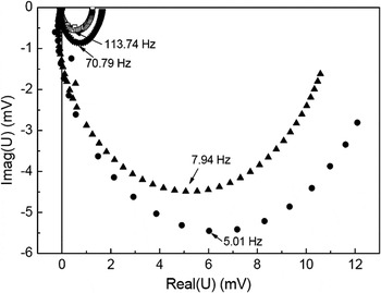
The time constant (τ n, lifetime of electron) can be estimated from τ n = (2πf max)−1, where f max is the characteristic frequency at the minimum imaginary voltage of IMVS at the imaginary voltage, which gives an estimate of the average time before the injected electrons are recombined by holes, dye cations, or oxidization compositions of redox electrolyte. For films with comparable film thickness, dye loading, and electrolyte compositions, such as those investigated here, the lifetime of electron should enable a valid comparison of the electron recombination with hole in the films. From the measured τ n value, one can estimate that the recombination process of electrons is different between the TiO2 and RuO2-modified TiO2 thin films. The lifetime of electron for the RuO2-modified TiO2 thin film electrode with four times adsorption and the TiO2 electrode without RuO2 modification are 31.8 and 1.4 ms, respectively. The reduction of electron recombination in the RuO2-modified TiO2 film is quite remarkable. Low electron recombination means an increasing in the lifetime of holes and thus ensures holes have enough time to degrade substrate, consequently improving photocatalytic performance. The reason that the RuO2-modified TiO2 thin film has lower electron recombination should be related to the shallow traps for holes formed by the modification of RuO2. But over-modification of RuO2 will form some surface states that can become recombination centers for electrons and holes. Therefore, the photodegradation efficiency begins to decrease over an adequate modification amount. And, for the adequate amount of RuO2, the homogenous distribution of RuO2 is also a very important factor for high photocatalytic performance. Otherwise, the aggregation of RuO2 even at an adequate amount will act as recombination sites to accelerate recombination of electron and hole. The adsorption of metal contained dye followed by sintering process, as a method to form homogeneous distribution of metal oxide on nanocrystalline porous thin film, will favor exact studying of the special properties due to homogeneous metal oxide modification.
IV. CONCLUSIONS
The nanoparticles colloidal paste prepared through the hydrothermal method was cast onto FTO glass substrate to form porous TiO2 thin film. The impregnation method and the dropping method were used to modify RuO2 on the porous TiO2 films, respectively. The impregnation method is to adsorb dye of N3 on TiO2 nanoporous film followed by sintering process to burn off organic matters and form ruthenium oxide. The modification amount of RuO2 was controlled by the iteration numbers of adsorption and sintering processes. In the dropping method, appropriate concentration of ruthenium trichloride trihydrate aqueous solution was dropwise added to the surface of TiO2 thin film, which was sintered at 450 °C to form RuO2 after evaporation of solvent. Eosin Y was selected as a substrate to estimate the photocatalytic efficiency of two kinds of RuO2-modified TiO2 films. The results indicate that appropriate modification amount of RuO2 can improve TiO2 photocatalytic performance by retarding recombination of hole with electron. RuO2-modified TiO2 prepared by the impregnation method exhibited better photocatalytic performance than that by the dropping method because of the uniform distribution of RuO2 formed by the impregnation method.
ACKNOWLEDGMENTS
Jingbo Zhang thanks Prof. A. Zaban of Bar-Ilan University, Israel for his kind and valuable suggestions. We acknowledge the financial support from the National Nature Science Foundation of China (20873162), the State Key Laboratory of Pollution Control and Resource Reuse Foundation (Nos. PCRRF09006, PCRRF08009, and PCRRY09004), and the Innovative Foundation of the Center for Molecular Science, Chinese Academy of Sciences (CMS-CX200718).