Introduction
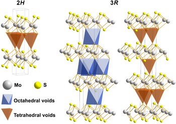
Tube, bulbous and fullerene-like nanostructures are known for many synthetic 2D-materials such as elemental carbon and Mo, Re and W disulfides, etc. They draw attention due to their outstanding structure-dependent properties such as immense specific surface, outstanding electrical and catalytic properties and the possibility of their application as lubricants (Ramakrishna et al, Reference Ramakrishna, Gomathi, Manna, Late, Datta, Pati and Rao2010; Spear et al., Reference Spear, Ewers and Batteas2015; Strachan et al., Reference Strachan, Masters and Maschmeyer2021 and references therein). Molybdenite has a layered structure formed by two-dimensional (2D) continuous layers consisting of trigonal prisms of MoS2 with a molybdenum atom in the centre and six sulfur atoms at the top and bottom. The layers are interconnected by Van der Waals bonds, which ensure the ease of plastic deformation of the mineral. Like most materials with a layered structure, molybdenite has several polytypic modifications, which differ in the mutual arrangement of alternating layers. Symmetry constraints allow the existence of five different structure types of MoS2 due to different layer adjustments (Takeuchi and Nowacki, Reference Takeuchi and Nowacki1964; Zvyagin and Soboleva, Reference Zvyagin and Soboleva1967). Wickman and Smith (Reference Wickman and Smith1970) calculated 112 theoretically possible molybdenite polytypes. Only two of these are known in Nature: the predominant two-layer 2H 1 with the space group P63/mmc, and more rarely the three-layer 3R with the space group R3m (Trail, Reference Traill1963; Newberry, Reference Newberry1979a). The space between 2D layers in the molybdenite structure can be represented as filled with hollow tetrahedra (2H 1) or tetrahedra and octahedra (3R), the tops of which are formed by sulfur atoms. In the 2H 1 and 3R polytypes (Fig. 1), molybdenum atoms of neighbouring layers are ‘obscured’ by sulfur atoms, which is the reason for structural stability (Chukhrov et al., Reference Chucrov, Zvyagin, Ermilova, Soboleva and Khitrov1968). The rigidity of the molybdenite structure is provided by the strength of the Van der Waals bonds between the sulfur atoms of adjacent 2D layers. The strength of bonds between 2D layers of molybdenite is proportional to 1/r2, where r is the distance between adjacent sulfur atoms. In the 2H polytype, the sulfur atoms in the interlayer space form rigid tetrahedra, in which three bonds are equivalent and have a length of 3.628 Å (Schonfeld et al., Reference Schonfeld, Huang and Moss1983). In the 3R polytype, two sulfur–sulfur bonds of 3.615 Å form a triangle in contrast to two other much weaker sulfur–sulfur bonds (5.75 Å) (Schonfeld et al., Reference Schonfeld, Huang and Moss1983), which allows the layers to slide relative to each other within a certain range. In the calculated polytype 2H 2, with an interlayer space filled with octahedra (Takeuchi, Nowacki, Reference Takeuchi and Nowacki1964; Zvyagin, Soboleva, Reference Zvyagin and Soboleva1967), molybdenum atoms in adjacent layers are not ‘shielded’ by the sulfur anion, this modification was observed in synthetic ReS2 and (Re,Mo)S2 only (Rekharskiy et al., Reference Rekharskiy, Savel'eva, Gorshkov and Dikov1983). Natural molybdenite sometimes consists of intergrowths of 2H 1 and 3R polytypes (Newberry, Reference Newberry1979b; Belogub et al., Reference Belogub, Lotova, Kotlyarov and Chesnokov1988; Plotinskaya et al., Reference Plotinskaya, Shilovskikh, Najorka, Kovalchuk, Seltmann and Spratt2019). Domains of the long period polytypes and disordered stacking sequences were found in natural molybdenite using scanning transmission electron microscopy (STEM) (Yang et al., Reference Yang, He, Xian, Xi, Wu, Chen, Zhu and Xu2022b). Despite the numerous studies carried out, the reasons for the polytypic diversity of natural molybdenite are still debatable.
Natural molybdenum disulfide polytype structures and the interlayer voids configurations and locations. For better clarity, the octahedral and tetrahedral voids of the 3R polytype are shown in separate figures. The crystal structure of molybdenite is drawn using Diamond – Crystal and Molecular Structure Visualization, ver. 3.2k3 software (Crystal Impact, Dr. H. Putz & Dr. K. Brandenburg GbR, Kreuzherrenstr. 102, 53227 Bonn, Germany).

In the Southern Urals, molybdenite-3R was first described by Yu.S. Kobyashev and G.F. Zvereva in the form of triangular tabular crystals and sheet aggregates in micaceous rock from the outer contact of anorthoclase pegmatites—veins No. 3 and 4 of the Slyudyanogorsk mica deposit (Kobyashev and Zvereva, Reference Kobyashev and Zvereva1978). Later, molybdenite-3R was found in veins No. 170, 175 and 179 of the Kyshtym high-purity quartz deposit (Talantsev et al., Reference Talantsev, Belogub, Grabezhev and Litoshko1990; Belkovskiy, Reference Belkovskiy2011). All these occurrences are located in the Ufaley metamorphic block of the Chelyabinsk region. The content and distribution of rhenium in molybdenite from the Slyudyanogorsk mica deposit was established by electron probe microanalysis (EPMA) (Kulikova and Maksimyuk, Reference Kulikova and Maksimyuk2014). Rhenium concentration was above the detection limit (0.04 wt.%) in 60% of the analysed points and reached 0.28 wt.%. The chemical composition of molybdenite-3R from other localities of the Ufaley block were not studied.
Unique scroll-like crystals of molybdenite-3R up to 3.5 cm in size were found by Yu.S. Kobyashev in the albitites of the interior contact of pegmatite vein No. 4 (Kobyashev and Zvereva, Reference Kobyashev and Zvereva1978). Twisted needle molybdenite up to 5 mm long were found in association with phengite mica of the outer contact of quartz vein No. 175 (Talantsev et al., Reference Talantsev, Belogub, Grabezhev and Litoshko1990).
We studied molybdenite-3R from vein No. 175 of the Kyshtym high-purity quartz deposit and pegmatite vein No. 4 of the Slyudyanogorsk mica deposit using X-ray diffraction (XRD), scanning electron microscopy (SEM), electron back-scattered diffraction (EBSD), electron probe microanalysis (EPMA), and inductively coupled plasma mass spectrometry (ICP-MS). The aim of this work is to elucidate the features of the chemical composition and crystal structure of twisted molybdenite-3R in comparison with platy forms and to assess the mechanism of its formation.
Brief geology of the Ufaley metamorphic block and sample location
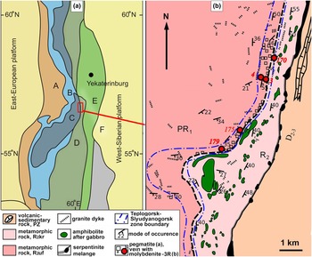
The Ufaley metamorphic block belongs to the Central Uralian megazone (Keylman, Reference Keyl'man1974; Puchkov, Reference Puchkov2017), (Fig. 2а). It is composed of a wide range of Proterozoic metamorphic and igneous rocks. The Paleoproterozoic Ufaley Formation occupies most of the Ufaley metamorphic block. It is represented by amphibolites, biotite and biotite–amphibole plagiogneisses with interbedding of quartzites, micaceous shales and migmatites. In the eastern part of the block, Neoproterozoic (Russian Riphean) rocks of the Kurtinskaya Formation (garnet–mica–quartz and micaceous-quartz shales interbedded with micaceous and graphite quartzites) form a narrow strip (Fig. 2b).
Geological setting of the studied deposit. (a) Scheme of the tectonic setting (simplified after Puchkov, Reference Puchkov2017). А – Preuralian foredeep, В – West Uralian zone, C – Central Uralian zone (exhumed Precambrian fundament), D – Tagil-Magnitogorsk zone, E – East Uralian zone, and F – Trans-Uralian zone. (b) Geological map of the Ufaley metamorphic block (simplified after Melnikov, Reference Melnikov, Gavrilov, Melnikova, Guskov and Gavrilova1964).

Numerous lenticular bodies of apogabbroic amphibolites occur in a matrix of metasedimentary rocks (Fig. 2b).
The Slyudyanogorsk–Teplogorsk suture zone is identified as an independent structural unit in the Ufalei block (Ogorodnikov et al., Reference Ogorodnikov, Polenov, Nedosekova and Savichev2016) (Fig. 2b). It is featured by intense placative and disjunctive dislocations and by numerous dykes of plagio-granites, granites, syenites, carbonatites and quartz veins of various ages and thicknesses. Greisens, albitites, quartz–feldspar and quartz veins associated with granitoids bear rare metal and rare-earth accessory mineralisation (Popova et al., Reference Popova, Muftakhov, Blinov and Kotlyarov2016). Accessory molybdenite is associated with quartz veins and muscovite pegmatites. All known occurrences of molybdenite-3R in the Ufaley block are located within the Slyudyanogorsk–Teplogorsk zone (Fig. 2b).
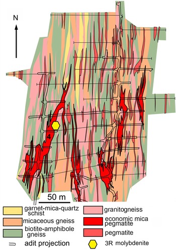
The Sludyanogorsk mica deposit is related to quartz–anorthoclase pegmatites hosted by a metamorphic sequence composed of an alternation of garnet–mica–quartz schists, micaceous and biotite–amphibole gneisses and granitic gneisses. The host rock sequence dips eastwards with a varying angle of incidence. Pegmatite bodies reach 150–200 m in length and 20 m in thickness (Fig. 3). Mica (phengite) rims often develop around the feldspar core of pegmatites (Ogorodnikov et al., Reference Ogorodnikov, Polenov, Nedosekova and Savichev2016).
Geological map of the Slyudyanogorskoe mica deposit (simplified after of D. Groznetskiy, Reference Groznetskiy1964). Vein No. 4 is marked.

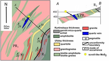
Quartz vein No. 175 is located in biotite–amphibole, biotite gneisses and granitogneisses injected with thin veins of granite–aplites, syenites and carbonatites. This quartz vein is concordant with the hosting sequences. The extension of the vein reaches 120 m with a thickness of up to 20 m (Fig. 4). Thin phengite bodies often occur near contacts of the quartz vein (Ogorodnikov et al., Reference Ogorodnikov, Polenov, Nedosekova and Savichev2016).
Geological map and cross-section along AB of the quartz vein No. 175 area (simplified after Melnikov et al., Reference Melnikov, Gavrilov, Melnikova, Guskov and Gavrilova1964).

Molybdenite aggregates were sampled near the contact of quartz–albite veins and thin bodies of biotite bearing phengite rocks in the adit of vein No. 4 of the Slyudyanogorsk mica deposit. Micaceous rocks traced the contact of pegmatite with host biotite and amphibole–biotite granitogneisses (Fig. 3).
Platy molybdenite was found in schistose micaceous and quartz–mica rocks developed at the exocontact of the quartz vein No.175. Scroll-like molybdenite was found in a concordant phengite body 50 cm in thickness occurring between quartz vein and hosting gneiss–amphibolite strata at the north wall of the quarry (Fig. 4).
Methods
The samples in the present study were either collected by the authors or provided by S.N. Nikandrov from his private collection.
The morphology and composition of minerals associated with molybdenite were studied using an AxioScope A.1 optical microscope and VEGA3 Tescan SBU scanning electron microscope (SEM), equipped with an Oxford Instruments X-act energy dispersive analyser (EDA) under the following conditions: accelerating voltage = 20 kV, beam current = 3 nA and counting time = 120 s. Standards from МАС (Micro-analysis consultants LTD, реr. No. 1362) and MINM25-53 (Astimex Scientific Limited, No. 01–044) were used. Crystal chemical formulae were recalculated to a 22 charge per formula for micas, 12 oxygen atoms per formula for garnet, 4 cations per formula for feldspars, 3 cations per formula for titanite and columbite-(Fe), 2 cations per formula for zircon and 1 cation per formulae for Nb-rich rutile. The water content in micas was recalculated by stoichiometry. Analytical totals of 100 +/– 1.5 wt.% (after calculation of H2O) were used as a criterion of analytical quality.
The contents of Re, W, Ta, Nb, Se, Te, Th and U in molybdenite were determined by ICP-MS using an Agilent 7700x mass spectrometer and the MassHunter software package with standards SGD-2а and ZUK. Decomposition of the molybdenite sample weighing 50 mg was carried out in a mixture of HF, HCl and HNO3. The destruction of fluoride complexes after decomposition was carried out by double evaporation of the dry residue of the sample with concentrated HNO3 under 110° С. The resulting precipitates were dissolved in a hot solution 0.5-N HNO3. All acids with the original qualification ‘special purity’ were additionally cleaned in a BSB-939-IR distillation unit (Berghof, Germany). Deionised water (Millipore) was used for dilution.
The analyses of the prepared solutions were carried out by the method of mass spectrometry with inductively coupled plasma (ICP-MS) using an Agilent 7700x. The purity of argon was not lower than 99.996%. The instrument was calibrated using standard multi-element solutions from INORGANIC VENTURES (USA) and rock standard samples from the Institute of geochemistry, RAS (Irkutsk, Russia). The analysis scheme included: analysis of calibration solutions and construction of calibration graphs; analysis of a ‘blank’ sample; and analysis of a batch of samples.
The polytype modification of molybdenite was determined by XRD patterns obtained from a disoriented preparation on a Shimadzu XRD-6000 (CuKα radiation with graphite monochromator1°/min, 2θ interval of 4–70°). Samples were prepared with a Vaseline substrate.
The above analyses were performed at the Institute of Mineralogy, Miass, Russia.
Distribution of the main elements in molybdenite-3R was studied using EPMA (Natural History Museum, London) using a Cameca SX100 microprobe. Operating conditions were: voltage = 20 kV, beam current = 40nA and a spot size of 1 μm. The following elements were determined: Mo, S, Se, Te, Fe, Cu, Zn, Re, W and Si. Peak overlaps and background positions were determined by analysing standards as unknowns. Peak overlap corrections were performed prior to matrix corrections (PAP) for major overlaps. Small overlaps (<0.2 wt.%) were corrected via empirical corrections post matrix correction. A high beam current was employed to gain improved counting statistics and a lower detection limit for Re (500 ppm).
At the local level, the polytype and crystal orientation were determined by back-scattered electron diffraction (EBSD) on a SEM HITACHI S-3400N, equipped with an Oxford HKLNordlysNano EBSD detector (Geomodel Resource Center, Scientific Park, Saint-Petersburg State University). The acquisition conditions were as follows: 30 kV (accelerating voltage), 1.5 nA (beam current) and 50 msec (dwell time per pattern), with an average of 2–5 images (when mapping) or 20 images (to obtain individual pictures) and subsequent processing using the Oxford AZtecHKL software package. Structural patterns of hexagonal and trigonal molybdenite from the Inorganic Crystal Structure Database (2H, ICSD31067; 3R ICSD40081) were used as the comparison phases.
To obtain a mechanically undistorted surface, the sample for EBSD analysis was treated with a direct beam of Ar plasma using an Oxford IonFab 300 etcher, an exposure time of 10 min, an angle of 45°, an accelerating voltage 500 V, a current 200 mA, and a beam diameter of 4 inches (Nanophotonics Resource Center, Scientific Park, Saint Petersburg State University).
The EBSD data is presented in a form of pole figures where all the orientation records are placed on a Wulff net and inverse pole figures are coloured maps where every unique orientation of a selected crystallographic axis is depicted with a specific colour (Mason and Schuh, Reference Mason, Schuh, Schwartz, Kumar, Adams and Field2009).
Impedance spectroscopy measurements were carried with an Agilent B1500A parameter analyser with microprobe station BS150. Prior to analysis, surfaces of scroll-like samples were covered with Auromal 38 silver paste and connected to an impedance analyser using the two-probe method. Impedance spectra were measured from 1 MHz to 1 kHz (10 points per decade).
A Novocontrol Concept 40 equipped with an impedance frequency analyser Alpha-A (Resource Center for Innovative Technologies and Composite Nanomaterials, Scientific Park, Saint Petersburg State University) was used to determine the electrophysical properties of molybdenite samples and to show the homogeneity of its crystals.
Results
Morphology and mineral association of molybdenite
Molybdenite from the micaceous border of pegmatite of vein No. 4 is represented by leafy aggregates with individuals up to 2 cm in size or tabular crystals up to 0.5 cm in size with pinacoid, trigonal dipyramid and small prismatic facets (Fig. 5a,b). Sometimes the crystals are twisted into a ‘half-scroll’ (Fig. 5c).
Position and morphology of molybdenite-3R in fine-grained albite near contact with phengite schist, vein No.4. (a) Position of molybdenite-3R net in adit; (b) trigonal crystals of molybdenite; and (c) ‘half-pipe’ crystal of molybdenite-3R.

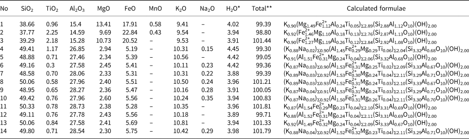
Molybdenite associates with quartz, mica (predominantly phengite (Table 1) with rare inclusions of biotite), albite, potassic feldspar (sometimes with a BaO impurity up to 0.65 wt.%), garnet of the almandine–spessartite–grossular series [(Fe2+1.13Mn0.93Ca0.60Mg0.10)Σ2.76(Al1.94Fe3+0.06)Σ2.00(Si1.00O4.00)3.00], Nb- and F-bearing titanite (Ca0.99(Ti0.75Al0.09Fe0.03)0.92Si1.03(O4.60F0.21)Σ4.81), columbite-(Fe), Nb-rich rutile (Table 2) and Hf-bearing zircon (Hf content 0.73–1.92 wt.%). Epidote and apatite(F) are rare.
Chemical composition and crystal-chemical formulae of biotite (analyses No 1–3) and phengite (analyses No 4–14), associated with molybdenite-3R.

Notes: 1–2, 4–6 = vein No. 4; 3, 7–14 = vein No. 175. ‘–’ = below limit of detection. * = H2O calculated by stoichiometry; ** total includes calculated water.
Chemical composition of Nb-rich rutile (1) and columbite-(Fe) (2–3), vein No. 4 (wt.%).

Notes: ‘–’ = below limit of detection.
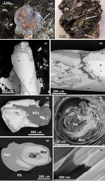
Molybdenite from vein No.175 has a leafy, tabular shape and reaches 1.5 cm in size (Fig. 6a). The molybdenite plates are sometimes bent and/or split. Scroll-like crystals of molybdenite reach 5 mm in length and 0.5 mm in diameter. In one sample, both platy and twisted crystals are present. Sometimes twisted crystals grow on the edge of platy crystals (Fig. 6a). The orientation of the tubules is chaotic (Fig. 6b). Scroll-like crystals have a smooth surface (Fig. 6c), on which triangular growth pyramids are sometimes visible at high magnifications (Fig. 6d), similar to the faces of the pinacoid of flat crystals (Fig. 6e). In the centre of most of the obtained sections of scroll-like crystals, a phengite plate or an intergrowth of biotite and phengite is found as a nucleation centre (Fig. 6f). The size of this mica ‘nucleus’ is 20–40 micrometres. The molybdenite layers around the prismatic belt of the mica crystal are corrugated (Fig. 6f,g). The ends of the tubes look like scrolls with very thin individual layers of the order of n × 10 nm (Fig. 6h). Supergene processes have resulted in a partial replacement of biotite by vermiculite and the replacement of molybdenite by powellite (Fig. 6g). The supergene origin of powellite relative to molybdenite is documented by the chaotic orientation of the former (Supplementary material S1).
Morphology of the molybdenite-3R in phengite schist from the the outer contact of vein No.175. (a) Platy crystal with a scroll-like unit at the periphery and in the matrix (marked by arrows); (b) scroll-like crystals in a phengite matrix; (c–d) triangle growth pyramids at the scroll surface; (e) triangle crystal with phengite; (f) seed ‘nucleus’ of platy phengite in the centre of the scroll; (g) cross section of the scroll with biotite (point a) and phengite (point b) with supergene powellite (Pwt) in the centre of the scroll; and (h) thin sheet of molybdenite. (a, b) macrophotos, (c–h) back-scatter electron images. Key: Mot – molybdenite, Ph – phengite, KFs – potassic feldspar, and Pwt – powellite.

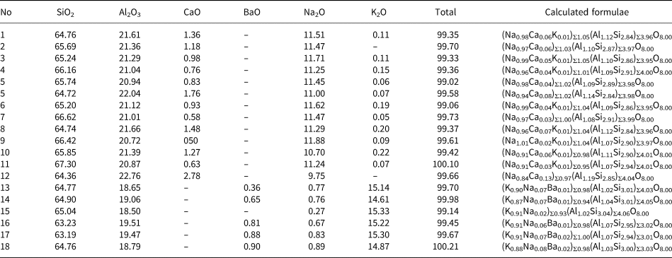
Both flat and twisted molybdenite-3R from quartz vein No.175 are associated with phengite and additionally rare biotite relics (Table 1). Molybdenite is associated locally with albite, potassic feldspar containing up to 0.90 wt.% BaO (Table 3) and F-bearing titanite, Ca0.99(Ti0.70Al0.25Fe0.04)Σ0.99Si1.02(O4.77F0.22)Σ4.99.
Chemical composition of feldspars (wt.%): plagioclase (1–12) and potassic feldspar (13–18), associated with molybdenite-3R.

Notes: 1–9, 13–15 = vein No. 4; 10–12, 16–18 = vein No. 175. ‘–’ = below limit of detection.
Structure
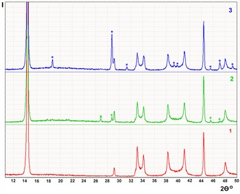
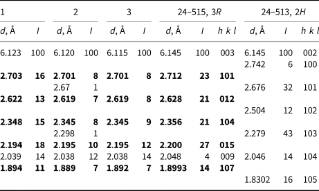
X-ray diffraction patterns obtained from platy crystals of molybdenite with (vein No.4) and without (vein No. 175) morphological signs of trigonal forms, and from scroll-like crystals of molybdenite from vein No. 175 correspond to the 3R polytype (Table 4, Fig. 7). Weak characteristic reflections of the 2H polytype are present within the XRD pattern of one of the platy crystals. The presence of strong lines for powellite confirm the partial oxidation of scroll-like molybdenite.
Partial XRD patterns of 3R molybdenites (CuKα radiation). Numbers correspond to specimens in Table 4. Stars indicate powellite reflections and the cross indicates quartz reflection.

Molybdenite d spacings for: 1 – platy molybdenite from vein No.4; 2 – platy and 3 – scroll-like molybdenite from vein No. 175; and standards from the Inorganic Crystal Structure Database (ICSD) for comparison.

Note: specific reflections of the 3R-polytype are in bold.
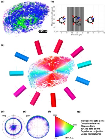
According to the EBSD data, both platy and scroll-like crystals are represented by a 3R polytype with an insignificant amount of the 2H polytype (Fig. 8, Supplementary material S2). The X axis serves as the axis of the scroll (Fig. 8a,c). The Z axis rotates perpendicularly around the surface of the scroll (Fig. 8b,c). Microtwinning is observed at an angle of 60° around the Z axis, as the twinning axis. Twining is due to the reversal of individual blocks in the (ab) plane. Molybdenite microtwins against the orientation of the host crystal form areas from 1–2 (resolution limit) to 220 μm in size. The larger ones have complex contours, sectorial shape and radiant orientation. Some microtwins exhibit a thin arcuate concentric shape (Fig. 8c,d).
EBSD image of scroll-like molybdenite-3R in a section perpendicular to the twist axis. (a) orientation of the Z axis relative to local MoS2 orientation (inverse pole figure (IPF) Z); (b) misorientation profile showing in-plane MoS2 3R microtwinning; the profile corresponds to a red arrow from (a); (c) orientation of the Y axis relative to local MoS2 3R orientation (IPF Y with visualisation using the corresponding unit cells; (d, e) pole figures showing the projection of the MoS2 3R {100} and {001} directions; (f) IPF X, Z legend; and (g) dataset and mapping information.

In areas of the prismatic belt mica, molybdenite probably originates parallel to minor fragments of pinacoid {001}, which are also present there (Fig. 6f,g). The total orientation of the molybdenite layers repeats the configuration of the edge of the mica plate. Further growth is accompanied by geometric selection yielding more ordered curved layers, which grew from more evolved pinacoid (001) mica (S2).
In order to detect an inclusion whose size is smaller than the SEM detection limit, electrophysical properties of scroll-like molybdenite were studied using dielectric impedance spectroscopy. All the crystals studied show typical half-circles on Bode plots (S3) which are attributed to volume resistivity of the sample. No interlayer dielectric 2D layers were found that could be captured from the environment due to mechanical twisting (S3).
Chemical composition and distribution of rhenium in molybdenite-3R
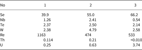
The maximum rhenium content (1163 ppm) is found within platy molybdenite from vein No. 4. Scroll-like and platy molybdenite from vein No 175 have a similar rhenium content, 533 ppm, and 474 ppm respectively. The Se, W, Nb and Te concentrations are significantly low and do not affect the structure of molybdenite (Table 5).
Minor elements in molybdenite from ICP-MS data (ppm)

Notes: 1 – platy crystals from vein No.4; and 2 – platy crystals and 3 – scroll-like crystals from vein No. 175.
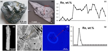
The distribution of the rhenium in both samples of molybdenite studied is not homogeneous. The platy molybdenite-3R from vein No.4 (Fig. 9a,b) has rhenium contents from below the detection limit to 1 wt.% (Fig. 7c). In the scroll-like molybdenite-3R from vein No. 175 (Fig. 9d) the zone with 0.12–0.39 wt.% of Re forms a contrast ring ~20 μm thick (Fig. 9f,g). The EPMA data are in close agreement with the solution ICP-MS data.
Rhenium distribution in (a–c) platy molybdenite-3R, vein No.4 and (d–f) scroll-like molybdenite-3R, vein No. 175. (a) Platy crystal; (b) back-scatter electron (BSE) image with marked line profile; (c) rhenium content from profile marked in (b); (d) BSE image of scroll-like crystal; (e) BSE image of perpendicular elongation of the scroll; (f) Re wt.% calibrated map; and (g) content of Re along the profile, marked on (e) and (f).

Discussion
Causes of the formation of molybdenite-3R
Many publications are devoted to the influence of impurities, in particular, rhenium, on the appearance of the 3R polytype of molybdenite (Khurshudyan et al., Reference Khurshudyan, Arutyunyan and Meliksetyan1969; Newberry, Reference Newberry1979a, Reference Newberry1979b; McCandless et al., Reference McCandless, Ruiz and Campbell1993; Strachan et al., Reference Strachan, Masters and Maschmeyer2021). As a rule, molybdenite-3R are enriched in rhenium, but сonsideration of the available analyses shows that high-rhenium natural molybdenites (up to 4.7 wt.%, Voudoris et al., Reference Voudouris, Melfos, Spry, Bindi, Kartal, Arikas, Moritz and Ortelli2009) can crystallise in the 2H polytype (Newberry, Reference Newberry1979b; Voudouris et al. Reference Voudouris, Melfos, Spry, Bindi, Kartal, Arikas, Moritz and Ortelli2009, Ciobanu et al., Reference Ciobanu, Cook, Kelson, Guerin, Kalleske and Danyushevsky2013). Moreover, 3R and 2H polytypes can coexist in a single sample (Belogub et al., Reference Belogub, Lotova, Kotlyarov and Chesnokov1988) or as crystals with thin intergrowths (Plotinskaya et al., Reference Plotinskaya, Shilovskikh, Najorka, Kovalchuk, Seltmann and Spratt2019; Yang et al, Reference Yang, He, Xian, Xi, Wu, Chen, Zhu and Xu2022b).
It has been shown experimentally that in the MoS2–ReS2 series the polytype modification 2H 1 is characteristic of sulfide with up to 26.43 wt.% rhenium content. Sulfides of molybdenum and rhenium where the content of rhenium exceeds 44.21 wt.% crystallised in the polytype modification 2H 2, and the trigonal modification was not recorded (Rekharskiy et al., Reference Rekharskiy, Savel'eva, Gorshkov and Dikov1983). Drabek et al. (Reference Drabek, Rieder and Bohmova2010) synthesised sulfides of the Re–Mo–S system in a temperature range of 400–1200°C. Experiments showed that molybdenite dissolved 2.7(9) wt.% Re at 1000°C and 2.2(6) wt.% Re at 400°C. The 2H polytype of molybdenite was obtained in all experiments by these authors.
Thus, despite the fact that natural 3R molybdenites are statistically more enriched in rhenium than 2H, the relationship between the content of this element and the polytype modification is not direct. It is possible that the 3R polytype can be formed by special growth conditions or other mechanisms.
Molybdenite-3R without rhenium content has been synthesised by dry and hydrothermal synthesis as a metastable phase into which collomorphic molybdenum sulfide is converted. Ultimately, molybdenite-3R transforms into a stable 2H 1 polytype. This transformation is monotropic (Khurshudyan et al., Reference Khurshudyan, Arutyunyan and Meliksetyan1969).
Experimental data and analysis of mineral parageneses show that the crystallisation of molybdenite-3R is facilitated by the reduced activity of sulfide sulfur (Clark et al., Reference Clark1970). These authors showed that molybdenite-3R is depleted with sulfur by 1–5% in comparison with the more stoichiometric 2H 1 polytype. However, subsequent work was not able to confirm this hypothesis (Newberry, Reference Newberry1979b). Nevertheless, Kumar et al. (Reference Kumar, Horwath, Foucher, Price, Acero, Shenoy, Stach and Jariwala2020) have obtained molybdenite-3R from monolayer MoS2 by heating. They explained the reason for 3R polytype forming was due to the stabilisation of the voids left by volatilisation of the sulfur atoms from within the structure. The 3R molybdenite from the Ufaley block studied in this work associates with Fe-bearing silicates and no sulfides, which may indicate a low sulfur activity.
Newberry (Reference Newberry1979 a,Reference Newberryb) and many later researchers (Strachan et al., Reference Strachan, Masters and Maschmeyer2021 and references therein) associated the formation of the 3R polytype with growth through screw dislocations, the appearance of which is facilitated by the incorporation of rhenium or other impurities into the molybdenite structure. The reason for the formation of such dislocations may be local enrichment in rhenium in the form of ReS2 nanoclusters. The layered structure of ReS2 consists of distorted octahedrons with sulfur coordinated Re, offset from the centre of octahedron (Murray et al., Reference Murray, Kelty, Chianelli and Day1994; Lamfers et al., Reference Lamfers, Meetsma, Wiegers and de Boer1996), in contrast to the Mo-centred prism of molybdenite. These features lead to corrugation of the layers, which can lead to the formation of a screw dislocation and beginning of the 3R polytype growth.
It is not only rhenium that can affect the molybdenite polytype. Yang et al. (Reference Yang, He, Tan, Tao, Yao, Xian, Sh, Xi, Zhu and Xu2022a) reported an abnormally high content of Pb and layered PbS precipitate within molybdenite grains which lead to disorder and the 3R-polytype forming. Molybdenite with low Pb content from the same deposit formed the 2H polytype. Thus, incoherent impurities may also be a reason for 3R-molybdenite forming. Molybdenite with prevailance of the 3R polytype enriched with rhenium up to 1 wt.% and selenium up to 15 wt.% was reported from Salla-Kuolajarvinskaya zone, Northern Karelia (Kalinin et al., Reference Kalinin, Savchenko and Selivanova2013).
A previous study of the surface structure of flat molybdenite-3R crystals from the Slyudyanogorsk deposit (Kulikova and Maksimyuk, Reference Kulikova and Maksimyuk2014) made it possible to reveal defects as screw and edge dislocations, among which plates and pits of a triangular shape dominate with a triangle side size of up to 40 μm. It was found that the groups of screw dislocations form growth spirals with the steps of up to 1200 μm in size. At the end of flat crystals molybdenite-3R, as submicrometre size tubes and cones with rhenium enrichment were found, though the distribution of the rhenium was inhomogeneous in the molybdenite crystals studied (Kulikova and Maksimyuk, Reference Kulikova and Maksimyuk2014).
In contrast, a study of 2H polytypes in rhenium-containing molybdenite samples using X-ray absorption spectroscopy (XANES) showed homogeneous distribution of rhenium within the molybdenite structure (Silva et al., Reference Silva, Figueiredo, de Oliveira, Veiga and Batista2013).
In the current investigation of platy and scroll-like molybdenites, the rhenium content reaches up to ~1 and 0.39 wt.%, respectively. Its distribution is not homogeneous. No other chemical impurities were found. Our impedance spectroscopic study shows no phase boundaries within molybdenite grains. It is likely that rhenium is the primary reason for crystallisation in the 3R polytype in this case.
Why are molybdenite crystals convolving?
Tube-like crystals in Nature are known from layered silicate structures of serpentine (chrysotile), kaolinite (halloysite) and cylindrite groups. In the cases of chrysotile and halloysite, twisting is caused with the different geometrical dimensions of the silicon–oxygen tetrahedrons layer and the octahedrons layer with magnesium (chrysotile) and aluminium (halloysite) (Giese, Reference Giese and Bailey1988; Wicks and O'Hanley, Reference Wicks, O'Hanley and Bailey1988). The scroll morphology of the cylindrite has another cause. The cylindrite structure contains two types of sheets, a pseudohexagonal one and a pseudotetragonal one, both with distinct lattice parameters. The core of the crystal has a different structure to its outer zone. The b and c axes of the two sheets are nearly parallel. Layer curving is one of the ways of accommodating the dimensional sheet misfit by a cylindrite crystal (Wang and Buseck, Reference Wang and Buseck1992). Scroll-like molybdenite in Nature is only found in the studied area, although WS2 crystallised in nanotubes with the same structure as MoS2 were discovered in 1992 (Tenne et al., Reference Tenne, Margulis, Genur and Hodes1992). To explain the reasons for the twisting of molybdenite, four mechanisms can be proposed: (1) crystal-chemical, related to the differences in the geometric dimensions of the layers due to their different chemical composition, as a result of which structural defects such as screw and edge dislocations appear; (2) associated with the presence of a specific nucleus within scrolls; (3) mechanical, due to tectonic movements during the mutual movement of two layers of rock; and (4) mechanochemical twisting of MoS2 nanolayers caused by colloid forces.
Mechanism 1: the structure of molybdenite is formed by flat 2D layers consisting of MoS6 prisms, where each sulfur atom is divided between two adjacent layers. In the first approximation, the ReS2 structure can also be represented as a sequence of 2D layers (Murray et al., Reference Murray, Kelty, Chianelli and Day1994; Lamfers et al., Reference Lamfers, Meetsma, Wiegers and de Boer1996). However, ReS2 layers have larger geometric dimensions in the (ab) plane than molybdenite. In both polytypes of molybdenite a o ≈ 3.16 (Schonfeld et al., 1981) with c 0 ≈ 12.3 Å for the 2H polytype and c 0 ≈ 18.3 for polytype 3R. In the synthetic disulfide of rhenium with the doubled unit cell the dimensions in the (ab) plane are: а 0 = 6.352 and b 0 = 6.446 Å (Lamfers et al., Reference Lamfers, Meetsma, Wiegers and de Boer1996). Based on the analysis of IR spectra in the longwave region, it has been shown that the structure of ReS2 is characterised by a decrease in the angle S–Re–S at the bridging rhenium atom as compared to molybdenum disulfide, which leads to deformation of the layers that form the crystal structure (Ionov et al., Reference Ionov, Kobrin, Mozhchil, Sigov, Syrov Yu and Fomichev2017). Thus, the presence in the molybdenite structure of nanoclusters significantly enriched in rhenium and, accordingly, having large sizes and being deformed in the (ab) plane, in comparison with 2D molybdenite layers, can lead to local distortion of the molybdenite structure and cause the onset of twisting of the layers. This is similar to the mechanism of the formation of tubular structures in chrysotile and halloysite. This theory is also supported by the nature of the twin boundaries, which intersect the c axis of the crystal, rather than lying parallel to the {ab} planes (Fig. 8a).
It should be noted that tubular, fullerene-like, and bulbous molybdenite nanoparticles have been synthesised several times (Houben et al., Reference Houben, Enyashin, Feldman, Rosentsveig, Stroppa and Bar-Sadan2012 and reference therein), but only nanoscale-crystals were obtained. Also, it was shown, that IF (inorganic fullerene-like)-MoS2 nanoparticles dopped rhenium are more stable under mechanical influence (tribological experiments) than the rhenium-free IF-MoS2, even at higher temperatures (Yadgarov et al., Reference Yadgarov, Petrone, Rosentsveig, Yi, Tenne and Senatore2013). This could be indirect evidence of the stabilising role of rhenium in naturally curled molybdenite macrosamples.
Mechanism 2: a tabular nucleus of biotite, phengite, or both of these minerals were present in the centre of almost all the molybdenite tubes studied (Fig. 6f,g, S2). The geometrical dimensions of mica in the (ab) plane are (phengite–biotite, Å) a o ≈ 5.23–5.38 and b 0 ≈ 9.06–9.32 (Bailey, 1984; Kish et al., Reference Kish, Sassi and Sassi2006). The value of b 0 of mica is about three times smaller (δ ≈ 4.5–1.7%) than a0 of molybdenite, which suggests the possibility of epitaxy in the (ab) plane. Overall the unit cell of molybdenite in the (ab) plane is larger than that of mica. This may be the reason for the initial out-of-plane distortion of the molybdenite layer and twisting of molybdenite around the mica nuclei. When molybdenite builds up on the prismatic belt of mica, there are no prerequisites for twisting, and the molybdenite is corrugated (Fig. 6f).
Mechanism 3: mechanical causes of crystal twisting cannot be completely ruled out. Molybdenite is soft, characterised by weak bonds between layers, and is therefore, easily deformed. The position of vein No. 175 in the zone of a long-lived fault (Teplogorsk–Sukholozhskaya suture zone) suggests periodically renewed geological movements. Samples with scroll-like molybdenite were taken from rheologically competent rocks, composed mainly of mica. Our samples contain platy crystals of molybdenite with one twisted edge, and among the studied individuals, we encountered arcuate ones. Thus, we have a full range of shapes from platy to tubular. This may indicate the influence of geological shear movements on the curling of molybdenite. Conversely the surface of the studied scroll-like crystals contains submicrometre triangular pyramids. The shape and position of such pyramids are clearly originated from crystal growth and cannot be generated by mechanical impact on original molybdenite. Triangular growth pyramids have been discovered previously on twisted molybdenite 4 cm in size from albitites from vein No. 4 (Talantsev et al., Reference Talantsev, Belogub, Grabezhev and Litoshko1990). The distribution of twins in a scroll-like crystal could indicate the growth direction of the crystal and its evolution. Thus, if the twins appear as overlapping layers (in our case, concentric), it can be suggested that a twin rotated by 60° with respect to the dominant one grown by means of edge dislocation (layer-by-layer). In the case of a twin boundary perpendicular to the layers, it can be assumed that screw dislocation is responsible for the initial twin nucleation. In both cases, molybdenite exhibits a growth twinning rather than mechanical. The assumption about the mechanical nature of twisted crystals is also contradicted by the different orientations of the tubes in the samples (Fig. 6b). Moreover, a sliding experiment carried out with a single poorly crystallised IF-MoS2 nanoparticle demonstrated exfoliation rather than scrolling (Lahouij et al., Reference Lahouij, Vacher and Dassenoy2014).
Mechanism 4: a more complex mechanochemical model can be described as a combination of fast growth of 2D flat molybdenite sheets and their adhesion to a matching surface (e.g. with capillary force) (Ma et al., Reference Ma, Liu, Xu, Ya, Kim, Yo, Zhong and Liu2017; Zhang et al., Reference Yu, Yin, Yo, Lee, Zangari, Cai and Xu2020) with bending or direct 2D layers deformation caused by a pressure difference due to wetting (Liechti, Reference Liechti2019). However, mechanical or chemo-mechanical twisting of already formed 2D layers of molybdenite in solution should result in the formation of thin layers of heterophase inclusions down to a few nanometres in size due to adsorption of heteroatoms from a solution on the molybdenite surface and/or physical capture of solution nanodrops. Dielectric impedance spectroscopy, however, shows no complex behaviour characteristic for dielectric or ionic inclusions. The impedance curve is typical for a bulk conductive crystal and can be matched by a single RC-circuit (Schönhals et al., Reference Schönhals, Kremer, Kremer and Schönhals2003). Thereby, no mechanical or chemomechanical models of formation of MoS2 scrolls from previously grown flat 2D thin can be considered.
Thus, the most probable model for the beginning of the formation of scroll-like molybdenites is the specific nuclei, followed by the layer-by-layer growth of tubes of the 3R polytype. The formation of the 3R polytype is caused by heterogeneous layers or clusters with different dimensions in the plane (ab), enriched and depleted in rhenium, regardless of the rhenium content.
Conclusions
Scroll-like crystals of molybdenite, 2–5 mm in size, were found in phengite rocks from the exocontact of feldspar pegmatites of the vein No. 4 (Slyudyanogorsk mica deposit) and in the vein of granular quartz No. 175 (Kyshtym quartz deposit), located in the Ufaley metamorphic block in the South Urals. Scroll-like molybdenite crystals can associate with platy and partly twisted crystals in the same samples. Both morphological types of molybdenite crystals are presented by the 3R polytype and enriched with Re up to 1 wt.%. Twisting occurs mainly around the crystallographic axis X. Twinning with a rotation of 60° around the crystallographic Z axis is fixed in the plane (ab). The most probable model for the formation of scroll molybdenites is the specific nuclei. The formation of this polytype is caused by the difference of the dimensions within the layers enriched and depleted in rhenium.
Acknowledgements
The authors are grateful to Maxim Lozhkin (Resource Center of Scientific Park SPbSU “Nanophotonics”) for preparing the surface of the samples for EBSD mapping. The work was carried out within the framework of the theme No. 075-00880-22-00. The EBSD study was carried out under RFBR, project No 19-05-00254.
Supplementary material
To view supplementary material for this article, please visit https://doi.org/10.1180/mgm.2022.35
Competing interests
The authors declare none