Introduction
Nickel-based Inconel 718 superalloy is a Ni–Fe–Cr austenite alloy, which has several good performances, especially in high-temperature working conditions. It is an essential material for manufacturing gas turbine blades, combustors, turbo charger rotors, and a variety of corrosion containments and structural applications up to 700 °C [Reference Amato, Gaytan, Murr, Martinez, Shindo, Hernandez, Collins and Medina1, Reference Cam and Kocak2, Reference Liu, Lin, Huang, Song, Yang, Chen and Huang3, Reference Chang4].
In recent years, many new designs of high-complex Inconel 718 components made by additive manufacturing (AM) provide an improvement in their performances. Differ from traditional subtractive manufacturing, the AM allows the design of the components more complex and more flexibility, such as integration design, internal flow path, grillage structure, etc.
Selective laser melting (SLM), as one of major AM technologies, supplies a promising perspective for designing and production of high-complex components with near net shape and has attracted more and more attention in aerospace and aviation industries [Reference Rong, Gu, Shi, Cao and Xia5, Reference Ali, Ma, Ghabeigi and Mumtaz6]. However, there are several challenges in SLM process which limit its further application and development, such as porosity, microcracks, thermal stress, residual stress, distortion, dimensional accuracy, and repeatability [Reference Mercelis and Kruth7].
Among these challenges, residual stress is one of key challenges which controls the formation of microcracks, distortion, and repeatability [Reference Khairallah and Anderson8]. The presence of tensile residual stress can be detrimental to the mechanical behaviors of SLM parts as well. It has been reported that several processing parameters may influence the residual stress distribution in SLM, such as laser power, scanning speed, scanning strategy, beam diameter, etc. [Reference Mercelis and Kruth7, Reference Khairallah and Anderson8, Reference Zeng, Pal and Stucker9, Reference Das10, Reference Song, Dong, Liao and Coddet11, Reference Thijs, Verhaeghe, Craeghs, Van Humbeeck and Kruth12]. However, most of the studies on residual stress through experiments are hard to analyze the evolution of thermal stress during SLM and the mechanism of the formation of residual stress, since the internal stress is almost unable to measure through experiments.
To understand how the processing parameters affect the residual stress distribution and their mechanisms, several research works focus on numerical simulations, which indeed provide some valuable information on the analysis and prediction of thermal stress evolution and residual stress formation. Yu et al. [Reference Yu, Gu, Dai, Xia, Ma and Shi13] established a 3D mesoscopic FEM to study the effect of processing parameters on the powder-to-solid transition during the process of SLM AlSi10Mg powder. It was found that the optimal processing parameters were laser power of 250 W, scanning speed of 400 mm/s, and powder layer thickness of 50 μm, which resulted in a relatively smooth surface and reasonable shrinkage value for AlSi10Mg samples. Li et al. [Reference Li, Fu, Guo and Fang14] conducted a multiscale FEM to forecast stress and distortion in the SLM process. Their simulations indicated that compared with vertical or island scanning strategy, the horizontal consecutive scanning strategy resulted in smaller substrate deformation. Cheng et al. [Reference Cheng, Shrestha and Chou15] developed a 3D sequentially coupled FEM to analyze the effect of scanning strategies on the part stress. Their results demonstrated that the out–in scanning strategy generated maximum stress components along X and Y directions, while the 45 inclined line scanning strategy reduced the stress components in both directions among all cases. Ali et al. [Reference Ali, Ghadbeigi and Mumtaz16] applied numerical simulations to examine the influence of scanning strategy on the residual stress and mechanical properties of SLM Ti6Al4V samples. Their conclusions were that the 90° rotate scanning strategy led to the minimum residual stress and scanning strategy hardly had effect on the mechanical properties.
Based on the literature study, it can be found that the processing parameters indeed can influence the residual stress distribution; however, the discussion of the mechanism of residual stress formation is limited. Therefore, to further understand the processing parameters affecting residual stress in SLM process, a thermal–elastic–plastic FEM and a restraint bar model are designed.
In this paper, through these models, influence of different laser volume energy density on the temperature field distribution and molten pool size during the process of SLM Inconel 718 powder are studied. The results of the model for the molten pool size are validated with the values measured from the optical metallography (OM). In addition, based on the temperature field, the mechanical simulation is conducted to research the effect of different laser scanning strategies on the residual stress distribution of Inconel 718 part. The restraint bar model is used to further analyze the formation mechanism of residual stress during the SLM process. The conclusions in this research may provide some theoretical guidance and data support for optimizing the technology parameters of SLM Inconel 718 alloy.
Result and discussion
Effect of laser volume energy density on the thermal behavior during SLM process
It is reported that laser volume energy density determines the size of molten pool and other thermal behaviors. Insufficient energy density results in poor metallurgical bonding, thus large amount of pores. Excessive energy density may lead to balling effect on the surface, which will affect the density as well. In this research, several combinations of laser power and scanning speed which represent different volume energy density are selected to reveal their effects on thermal behaviors in detail.
In our previous study, the simulated temperature distribution around molten pool size was analyzed, and details were found in Ref. Reference Zhang, Wu, Lu, Ni, He, Yang, Zhu and Gu17. It is clearly shown an asymmetrical thermal field during SLM process. Along the scanning direction, the temperature gradient in the front area is much higher than in the back area, which is mainly caused by the movement of laser beam. In perpendicular direction of scanning, the ellipsoidal temperature distribution shifted to the scanned solid side. This can be attributed to the fact that the solidified section and the powder bed have different conductivity.
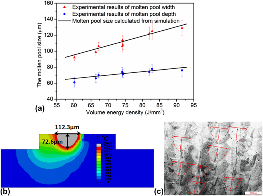
Larger volume energy density causes wider and deeper molten pool, both in the simulated result and in the experimental measurement, as shown in Fig. 1(a). The molten pool sizes from experimental measurement are in good agreement with simulated prediction. An example of simulated molten pool under laser power of 285 W and scanning speed of 960 mm/s and its experimental measurements are shown in Figs. 1(b) and 1(c), respectively. It is worth to notice that if we compare the cases which have similar volume energy density but with different laser power and scanning speed, we can see that laser power might have a slightly stronger effect on molten pool than scanning speed.
Simulated melting pool and experimental results: (a) effect of laser volume energy on the size of melting pool, both simulated result and experimental results; (b) an example of simulated melting pool under laser power 285 W and scanning speed 960 mm/s, gray area represents melting pool; and (c) an example of experimental results under laser power 285 W and scanning speed 960 mm/s using metallographic microscope.

Effect of laser volume energy density on the residual stress distribution
In SLM, the solidification process of the molten metal will cause the localized inhomogeneous contraction, which will result in the formation of internal stress. During the whole cyclic heating and cooling, the internal stress evolves continually with the development of thermal conditions and finally forms the residual stress in SLM parts. The distribution of internal stress and residual stress is crucial to the distortion and the formation of cracks in SLM. Thus, understanding the mechanism of stress formation and optimizing processing parameters to alleviate the detrimental effect of tensile internal and residual stress are hot research areas in SLM.
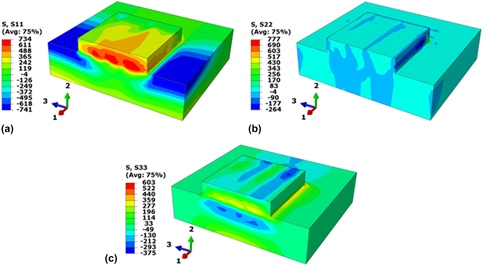
In this research, the typical distribution of residual stress in selective laser melted part is modeled and discussed. An example of simulated residual stress distribution under laser power of 285 W, scanning velocity of 960 mm/s, and scanning strategy (a) are shown in Fig. 2. S11 represents the residual stress component along scanning direction, S33 represents the residual stress component perpendicular to scanning direction, and S22 represents the residual stress along deposited direction. It is interesting to find that the residual stress of Inconel 718 specimen is mainly tensile stress and the maximum S11 and S33 tensile stresses usually appear close to the surface layer, as shown in Figs. 2(a) and 2(c). The S22 is above 700 MPa and primarily concentrated in the four bottom corners of the contact area between the SLM Inconel 718 part and substrate. This can be attributed to the large S11 and S33 tensile stresses which result in the tendency of buckling. It is worth to notice that, during the SLM manufacturing processing, the sensitive area of cracking usually appears in the corner area between deposited parts and substrate. This is similar to the simulation result in this research, which means that the FEM used in this study has a good prediction ability for the tendency of residual stress distribution in the SLM process.
An example of residual stress distribution in the SLM specimen under laser power 285 W and scanning speed 960 mm/s, using long-path scanning: (a) the residual stress component along scanning direction, (b) the residual stress along deposited direction, and (c) the residual stress component perpendicular to scanning direction.

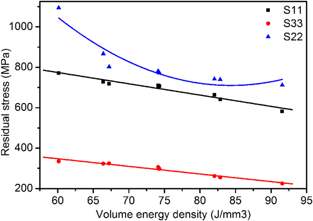
Similar to temperature field analysis, the relationship between volume energy density and residual stress is worth to investigate as well. Figure 3 describes the influence of volume energy density on the max residual stress in Inconel 718 specimen in this research. From the simulated results, it is clearly shown that the max residual stress decreases linearly with the increase in volume energy density. As the volume energy density increases from 60.14 to 91.57 J/mm3, the residual stress components decrease from 771 to 582 MPa for S11, from 334 to 224 MPa for S33, respectively. The above simulated results show that a higher laser heat input will decrease the residual stress of the SLM Inconel 718 sample, which ultimately helps to reduce the deformation and cracking tendency of the sample during and after SLM process.
Effect of laser volume energy on the residual stress distribution.

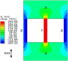
To further reveal the mechanism of residual stress formation in the SLM process and why the laser volume energy density reduces residual stress, a self-designed constraint bar model is proposed in this study, as shown in Fig. 4. The constraint bar model consists of three independent bars, and all connect to a nearly rigid part, which forms a frame structure. The total frame used in this model is 200 × 50 × 4 mm, while the dimension of each bar is 40 × 4 × 4 mm. A volumetric heat flux with uniform density was applied in the middle of bar 1. The middle part of bar 1 was heated up 1600 °C and then cooled down to room temperature.
The residual stress distribution after heating and cooling in constraint bar model for analysis of residual stress formation during and after SLM.

The SLM procedure can be simply represented by this 3-bar model. The bar 1 represents the fusion area. The cold base materials around fusion area are represented by bar 2. The region 3 can be considered as rigid materials, which are far away from the moving laser scanning area during SLM. Using this bar model, the evolution of internal stress and the formation of residual stress can be revealed clearly.
Figure 4 demonstrates the residual stress distribution after heating and cooling. It is clearly shown that the heated area (bar 1) presents a strong tensile residual stress, while the unheated area (bar 2) presents a compressive residual stress. This kind of residual stress distribution can be normally found in localized heating processes, such as welding and SLM.
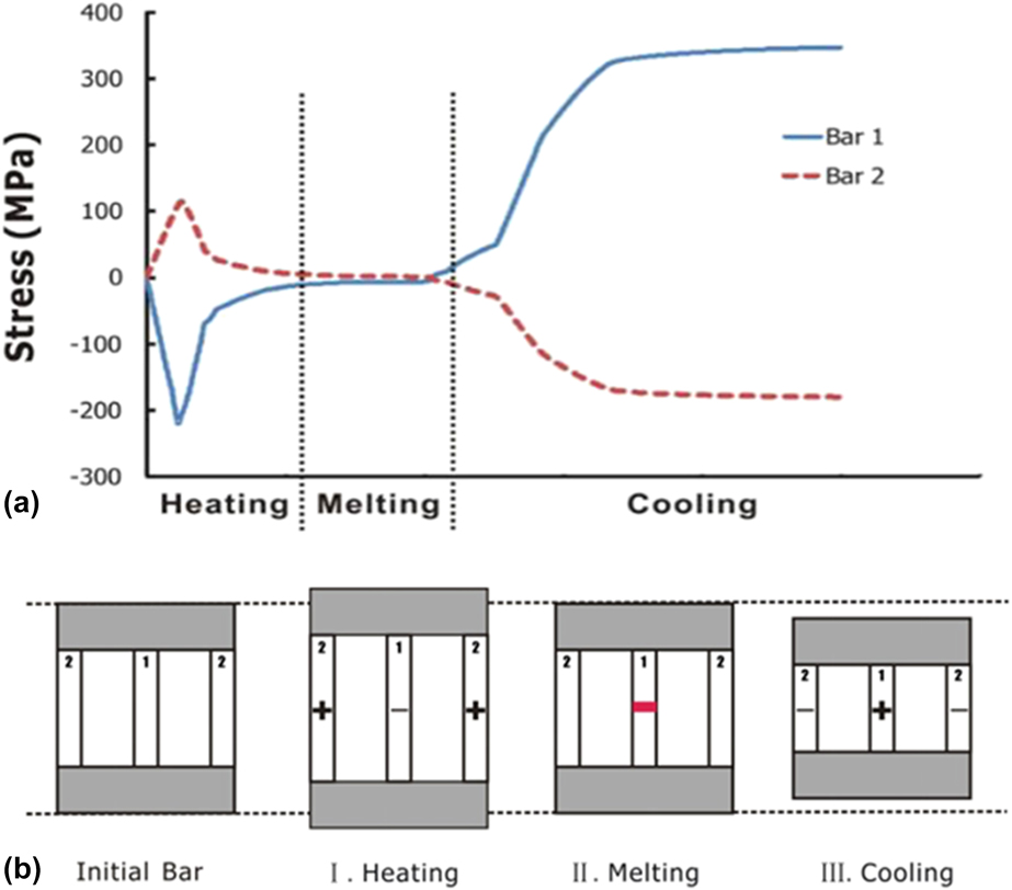
To reveal the mechanism of residual stress formation, the evolution of thermal stress during heating and cooling in constraint bar model is analyzed, as shown in Figs. 5(a) and 5(b). During the heating process, the center area in bar 1 first expanded due to thermal heat input. However, this expansion in the direction along the bar was hindered by surrounded cold region in bar 2. This resulted in the compressive stress in bar 1 and tensile stress in bar 2. With the increase in temperature in bar 1, the material started to yield and the developed stress decreased. When the material was melting, no stress can be built up, as shown in Fig. 5(a). During the cooling stage, the subsequent cooling led to the contraction of bar 1. This contraction was again hindered by bar 2, which caused the development of tensile stress in bar 1 and compressive stress in bar 2. After cooling down to the room temperature, the original cause of the stresses had been removed. However, the tensile stress in bar 1 and compressive stress in bar 2 still remained in the material as residual stress. Figure 5(b) is a schematic diagram for the evolution process of different restraint bars in the SLM process.
(a) Stress evolution in three bars during heating and cooling. (b) A schematic diagram for the evolution process of different restraint bars in the SLM process.

The simulated stress evolution in different restraint bars clearly shown that the locally uneven heating and local self-constraint state, which are caused by the fast moving laser, will lead to the cycle evolution of the internal stress and the formation of residual stress. Therefore, the temperature field distribution of SLM process plays a crucial role in the evolution of internal stress and the formation of final residual stress. However, in real SLM processing, the stress development and the formation of residual stress are much more complex due to the moving heat source and the different geometries of the components and need to be further analyzed case by case.
Role of scanning strategy in the residual stress distribution
As mentioned above, the residual stress and internal stress are greatly affected by the temperature field distribution during SLM. Therefore, it is worth to study one of main factors affecting the temperature field distribution: scanning patterns. This factor can strongly influence the temperature field distribution in the SLM process, thus determining the local self-constraint conditions in the solidification shrinkage process.
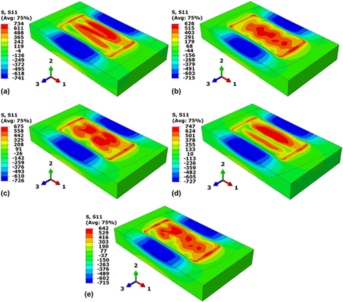
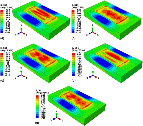
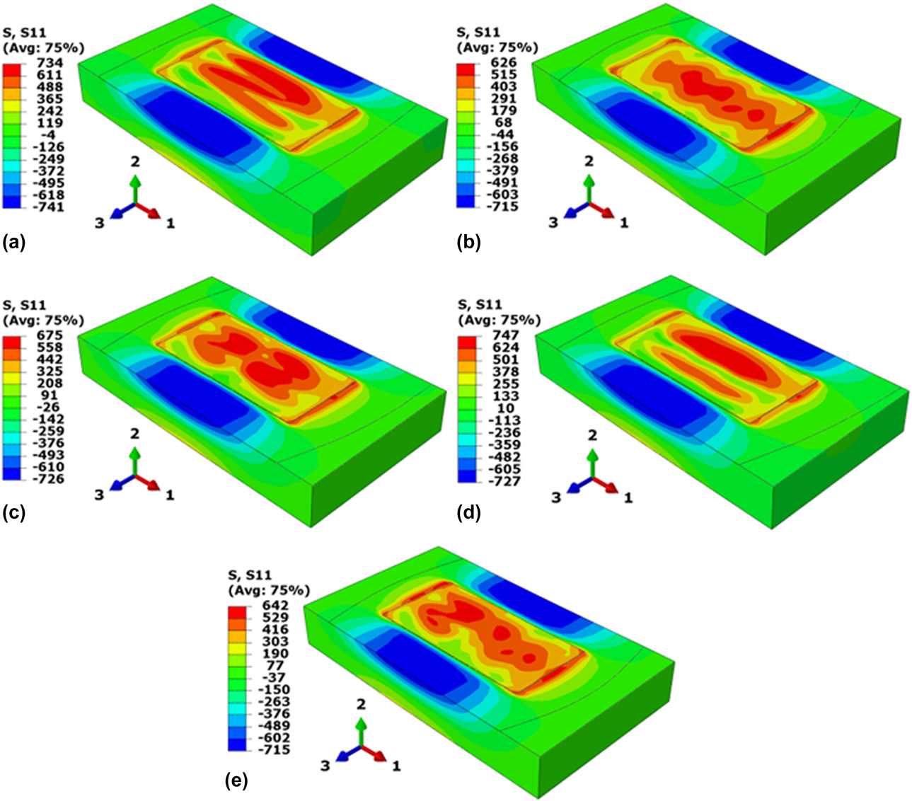
In this study, five scanning strategies are selected to investigate the residual stress of Inconel 718 parts manufactured by SLM using FEM. Figure 6 shows the distribution of the residual stress filed using different scanning strategies. It can be clearly seen that the residual stress distribution of SLM Inconel 718 specimen largely depends on the scanning strategy, and the scanning patterns can be roughly inferred from the residual stress distribution. This phenomenon is because that the different scanning strategies lead to different local thermal cycle and constraint condition during the solidification process. In addition, it can be found that the peak value of the residual stress usually occurs near the end point of the laser scanning area. This might be mainly attributed to the fact that there is no reheating process in the vicinity of the end point of the laser scanning, which leads to the development of the tensile residual stress during cooling stage.
Effect of scanning strategy on the residual stress distribution.
Conclusions
In this study, a thermal–elastic–plastic 3D FEM is proposed to investigate the effect of volume energy density on the temperature field, molten pool size, and residual stress distribution in the SLM process of Inconel 718 alloy. The simulated result of molten pool size is validated by the experimental results and shows a good agreement. In addition, five scanning strategies are adopted to study the effect of different scanning patterns on the residual stress distribution in this research. To reveal the mechanism of residual stress formation, the restraint bar model is used to further analyze the formation mechanism of residual stress during the SLM process. Several conclusions can be drawn from this research.
(1) The molten pool sizes increase with increasing volume energy density, both in the simulated result and in the experimental measurement. And within the scope of the study parameters, the volume energy density and molten pool size exhibit linear growth relationship.
(2) Within the scope of the study parameters, a higher laser heat input can decrease the maximum residual stress of the SLM Inconel 718 sample.
(3) The residual stress distribution of SLM Inconel 718 specimen largely depends on the scanning strategy. This is because the different scanning strategies lead to different local thermal cycle and constraint condition during the solidification process.
(4) The temperature field distribution of SLM process plays a crucial role in the evolution of internal stress and the formation of final residual stress. The locally uneven heating and local self-constraint state caused by the fast moving laser beam determine the final residual stress distribution in SLM process.
Model and experiment description
Finite element model and experiments for thermal analysis
In this study, a thermal–elastic–plastic finite element model is developed for calculating temperature distribution and residual stress field during and after SLM. It is reported that the dimensional change and stress build-up procedure have minor effect on thermal field development and can be negligible during thermal analysis. Thus, the calculation procedure in the model consists of two steps. Firstly, the heat input, heat conduction, and heat loss during SLM are modeled independently from the stress analysis. After obtaining the temperature history during the whole SLM processing, the temperature field is employed as a thermal load in the subsequent mechanical–elastic–plastic model to calculate the stress evolution during SLM and final residual stress distribution.
The thermal model is based on a 3D finite element approach. For a function q(x, y, z, t) of three spatial variables (x, y, z) and the time variable t, the thermal conduction equation in the model can be described as follows [Reference Ali, Ghadbeigi and Mumtaz18]:
 $${{\partial q} \over {\partial t}} = {k \over {\rho {C_{\rm{P}}}}}\left( {{{{\partial ^2}q} \over {\partial {x^2}}} + {{{\partial ^2}q} \over {\partial {y^2}}} + {{{\partial ^2}q} \over {\partial {z^2}}}} \right)\quad ,$$
where q is heat flux, ρ is density, C P is heat capacity, and k is thermal conduction coefficient, and the material is believed to be isotropic in (x, y, z) directions.
To reduce the computational cost and reveal the basic law of the effect of heat input, a two-layer scanning model is selected in this study, which consists of a two-layer powder bed with the dimension of 0.80 × 0.40 × 0.08 mm and an dense substrate with the dimension of 1.40 × 0.80 × 0.20 mm. The element dimension is 0.0125 × 0.0125 × 0.0125 mm in the powder layer with 8-node linear hexahedral element type to improve the computational accuracy in the scanning area, while the substrate has coarser mesh whose size is set to gradually increase with the distance away from the scanning domain [Reference Cheng, Shrestha and Chou15]. As a result, the three-dimensional simulation model is meshed into 34,881 nodes and 30,296 elements in total.
Considering the laser penetration and the transient thermal transportation phenomenon in the SLM process, the continuous heat source is applied as a moving modified Gaussian heat source distribution [Reference Goldak, Chakravarti and Bibby19, Reference Goldak, Bibby, Moore, House and Patel20],
 $$q\left( {x,y,z} \right) = {{\eta \cdot 6\sqrt 3 Q} \over {h{r^2}\pi \sqrt \pi }}\exp \left( { - {{3{x^2}} \over {{r^2}}} - {{3{y^2}} \over {{r^2}}} - {{3{z^2}} \over {{h^2}}}} \right)\quad ,$$
where q(x, y, z) is the heat flux density of point (x, y, z) in the coordinate system, Q is the laser power, η is the laser absorptivity of powders, r represents the radius of Gaussian laser beam, and h is the depth of Gaussian heat flux. The laser scanning direction and magnitude of heat source are controlled by a self-developed FORTRAN program.
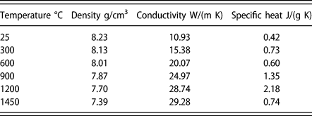
To improve the accuracy of the model, differences of thermo-physical performance between the powders and solidified parts are considered and summarized in Table I. Under the effect of laser scanning, when the temperature of the powder layer exceeds the solidus line, the thermo-physical properties of the powder layer are set to be automatically transformed into the thermo-physical properties of the solidified material, and the state of the solidified parts will be maintained in the subsequent cooling process [Reference Song, Wu, Zhang, He, Lu, Ni, Long and Zhu21]. This thermo-physical conversion process from powder to solidified part after laser scanning is realized through a self-developed program.
Thermo-physical properties of Inconel 718 alloy used in the model.

The thermo-physical properties are theoretically calculated from the room temperature to melting point of Inconel 718 alloy with the interval of 300 °C, because the main purpose of this study is to investigate the tendency of influence of laser volume energy density on thermal behavior. To simulate the strong convective effect on the molten pool at high temperature, the thermal conductivity of liquid phase is as assumed to be three times that of the solid phase below the solidus. The surface convective and heat radiation effect of the powder and the substrate are considered in the model by using a temperature-dependent comprehensive thermal parameters A [Reference Lee, Chang and Park22]:
 $$A = \left\{ {\matrix{ {0.0668T} \hfill & {0 \lt T \lt 500\;^\circ {\rm{C}}} \hfill \cr {0.231T - 82.1} \hfill & {T > 500\;^\circ {\rm{C}}} \hfill \cr} } \right.\quad ,$$
in which the unit of comprehensive thermal parameters (A) is  ${W \over {{m^2}K}}$.
Afterward, the whole structure is cooled down to room temperature to analyze the residual stress distribution.
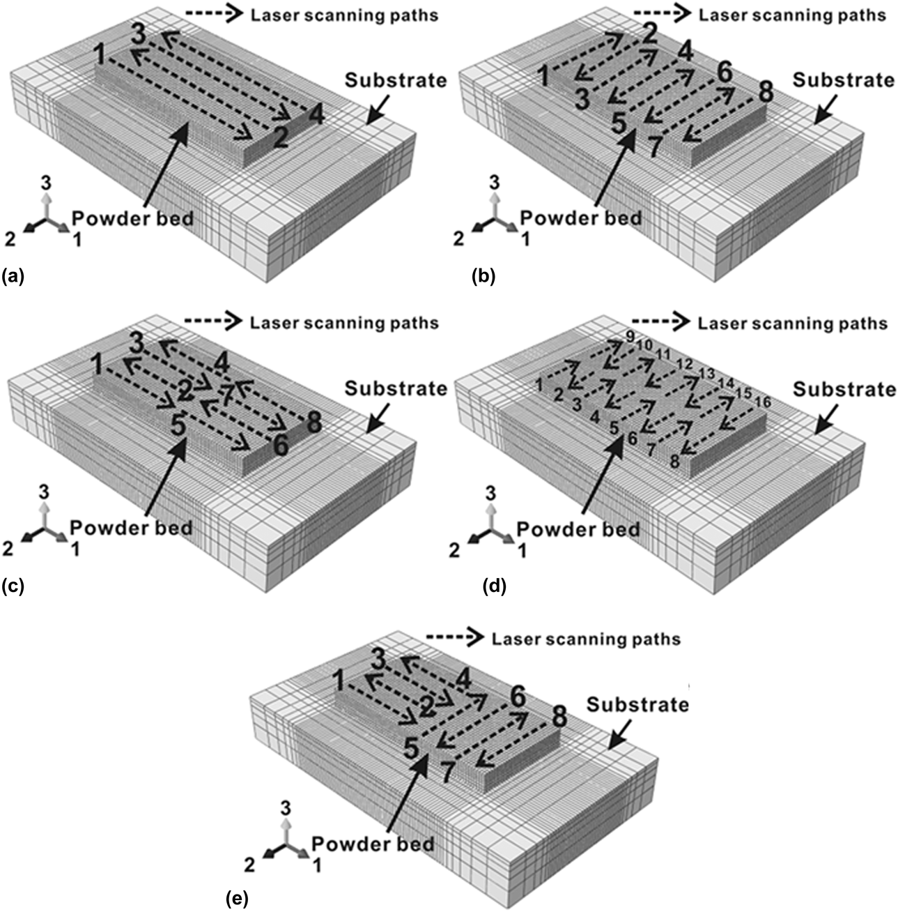
In this research, several laser scanning strategies are selected in the model to reveal their effect on thermal behavior and residual stress distribution. Different scanning strategies are shown in Fig. 7. The laser moving paths in each scanning strategy are illustrated using arrows and are ordered in number.
Three-dimensional finite element model for scanning strategy analysis used in this study: (a) long-path scanning, (b) short-path scanning, (c) partition long-path scanning, (d) partition short-path scanning, and (e) partition vertical scanning.

Finite element model for structural analysis
In the structural analysis, the nodal temperature history obtained from thermal model is used as input data for mechanical simulation. It is well known that the residual stress distribution is affected by local thermal history and its mechanical constraint condition. To reveal the mechanism of the formation of residual stress caused by thermal input during SLM, three vertices on the top surface of substrate are constrained in (x, y, z), (x, y), and (x) directions, respectively, to avoid the rigid movement of the model.
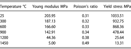
In this study, temperature-dependent Young’s modulus, Poisson’s ratio, and yield strength are used not only to improve the accuracy of the model, but also to make our simulations closer to the actual situation, since the SLM process involves yield, heat shrinking, and thermal expansion of Inconel 718 alloy. Like thermo-physical properties, the mechanical properties are also derived from theoretical calculations and listed in Table II.
Mechanical properties of Inconel 718 alloy used in the model.

Experimental procedure for model validation
An EOS M290 SLM equipment is applied to fabricate Inconel 718 specimens for model validation. This installation consists of a fiber laser beam as the forming energy with a maximum power of 400 W and a laser spot diameter of 80–150 μm before SLM processing, and the stainless-steel substrate is preheated to 200 °C. To verify simulation results, the processing parameters in the experiments are the same as the data in the simulations. The chemical composition of Inconel 718 powder is listed as follows (mass fraction. %): 5.26 Nb, 17.30 Cr, 19.36 Fe, 0.05 Mn, 3.52 Mo, 0.83 Ti, 0.52 Al, 0.07 C, 0.01 V, 0.08 W, and 52.89 Ni.
In SLM process, laser volume energy density E is a key factor affecting the metallurgical characteristics of products, which is a measure of the averaged applied energy per volume of material during the scanning of a layer:
 $$E = {P \over {V \cdot h \cdot t}}\quad ,$$
where P is the laser power, V is the scanning velocity, h is the hatch spacing, and t is the layer thickness. In our research, the h and t are fixed at 100 μm and 40 μm, respectively, so the values of E are 60.14, 66.41, 67.22, 74.12, 74.22, 74.29, 82.03, and 82.85 J/mm3 in this study.
The SLM Inconel 718 specimens are cut into small pieces, ground, and polished carefully. Specimens are then slightly eroded by a mixture of hydrochloric acid, water, and hydrogen peroxide  $\left( {{V_{{\rm{HCl}}}}{\rm{:}}{V_{{{\rm{H}}_2}{\rm{O}}}}{\rm{:}}{V_{{{\rm{H}}_2}{{\rm{O}}_2}}} = 2{\rm{:}}1{\rm{:}}1} \right)$. The cross-sectional microstructure of the eroded part is examined by an OM. In the metallographic microanalysis, the sizes of 20 clear molten pools are measured and then averaged.
Acknowledgments
This work is supported by the project to strengthen industrial development at the grass-roots level (Project No. TC160A310/19), Natural Science Foundation of Shanghai (Project No. 17ZR1409200), Shanghai Rising-star program (Project No. 18QB1400600), and Shanghai Materials Genome Institute No. 5 (Project No. 16DZ2260605).