1. Introduction
The accelerometer is the core of an inertial navigation system (INS), which is used to provide the corresponding position information of the carrier accurately. For this reason, improving the calibration accuracy of the accelerometer is necessary to enhance the navigation accuracy of the INS. Currently, the INS accelerometer is calibrated separately and carried out mainly in a 1 g gravitational field (Rohac et al., Reference Rohac, Sipos and Simanek2015; Bruns and Gazioch, Reference Bruns and Gazioch2016; Shengnan, Reference Shengnan2019). However, the installation misalignment affects the calibration accuracy (Sun et al., Reference Sun, Ren and Wang2019) in the process of disassembly and installation of the accelerometer. The maximum input-specific force of the accelerometer in a 1 g gravitational field is not enough to effectively stimulate the higher-order error coefficients of the accelerometer. It does not meet the navigation conditions of high-acceleration flight. Therefore, large excitation and overall calibration of the accelerometer is the mainstream of inertial instrument calibration research.
The overall purpose is to calibrate all the error model coefficients of the three accelerometers in an inertial measurement unit and at the same time reduce the influence of the test equipment error on the calibration accuracy of those coefficients. A calibration method based on the norm-observation method proposed by Lötters et al. (Reference Lötters, Schipper, Veltink, Olthuis and Bergveld1998) can solve the problem of over-dependence on a turntable and significantly reduce the influence of turntable errors on the calibration results of error model coefficients. Hongliang et al. (Reference Hongliang, Yuan-xin, Ya-bing, Mei-ping and Xiao-ping2010) used quaternions to construct an error model about axes perpendicularity errors and angle-control errors of a turntable. Considering measurement errors of gyroscopes and accelerometers in an inertial measurement unit (IMU), they derived the calibration parameters’ errors using a typical multi-position calibration method. Final simulations and calibration tests of a laser gyro strapdown INS were performed to verify the calibration error analysis. On this basis, Chun-mei et al. (Reference Chun-mei, Shun-qing and Xi-jun2018) calibrated the zero bias and the scale factor of a single gyroscope and accelerometer in a 1 g gravitational field by using the norm-observation method. The process focused on the influence of installation errors.
Shaowu et al. (Reference Shaowu, Kehong and Hongde2014) introduced the navigation attitude calculation into the calibration of MIMU (multi-inputs/multi-outputs). The method used quaternions to solve the attitude in the process of MIMU rotation, and established the nonlinear equations of norm-observation for MIMU calibration. Thus, the method makes the calibration of all the parameters of MIMU come ture, and the improved particle swarm optimisation (PSO) algorithm based on the logistic function was applied to the calibration of MIMU. Shi-ming and Shun-qing (Reference Shi-ming and Shun-qing2013) introduced a method of calibrating medium and high-precision INS without a turntable, and calibrated the coefficients of the accelerometer according to the principle that the vector sum of the accelerometer output on the orthogonal axis is equal to gravity.
The norm-observation method is still studied in a 1 g gravitational field or on a low-speed turntable. Because the error model does not include higher order coefficients, it cannot adapt to the application environment of the high-speed flight of INS.
The precision centrifuge can continuously provide high-precision acceleration of more than 1 g, which is typically used to identify the higher-order coefficient model of the accelerometer (Guanjinzi et al., Reference Guanjinzi, Jianchen, Hai and Gang2017; Shengli et al., Reference Shengli, Hepeng, Jichang, Zhenghu and Chunjing2018), which lays a good foundation for obtaining the accelerometer coefficient model with higher-order terms.
However, the calibration accuracy is affected by the difference of calibration methods due to the existence of precision centrifuge errors. In the actual calibration process, it is often necessary to design certain testing methods to compensate, avoid, restrain or even eliminate the errors (Li et al., Reference Li, Song, Wang, Niu and Li2018; Shaowu et al., Reference Shaowu, Qiangqiang, Zijian and Hongde2018).
Using the norm-observation (Xu et al., Reference Xu, Zhu and Su2014; Yang et al., Reference Yang, Gong-liu, Qing-zhong and Li-fen2021) method, the whole calibration method of the accelerometer combination is studied with a high-speed rotating precision centrifuge as the calibration equipment, with emphasis on the calibration principle of the norm-observation method for the quadratic coefficient of the accelerometer. The mathematical expression of the calibration result of the error model coefficient is given by means of mathematical methods such as the Taylor expansion formula and least square method. At the same time, the influence of installation misalignment and rod-arm error on the calibration accuracy is considered. This work lays a foundation for improving the calibration accuracy of inertial assembly.
2. Calibration equipment
2.1 Structure of centrifuge and coordinate system
To accurately calibrate each coefficient, a high-precision centrifuge with an counter-rotating platform is selected as the calibration equipment, and the coordinate system and its structure diagram are established as shown in Figure 1.
Schematic diagram of inertial assembly structure for centrifuge calibration

In Figure 1, ${O_a}{X_a}{Y_a}{Z_a}$ is the geographic coordinate system, ${O_b}{X_b}{Y_b}{Z_b}$
 is the sleeve coordinate system of the main axis, ${O_k}{X_k}{Y_k}{Z_k}$
 is the coordinate system of the counter-rotating platform, and ${O_{2t}}{X_{2t}}{Y_{2t}}{Z_{2t}}$
 is the sleeve coordinate system of the counter-rotating platform axis. R is the nominal radius of the centrifuge; ω is the angular velocity of the centrifuge; A is the centripetal accelerations generated by the centrifuge; and its value is ω 2R, the direction of acceleration due to gravity is upward.
2.2 Structure of accelerometer combination
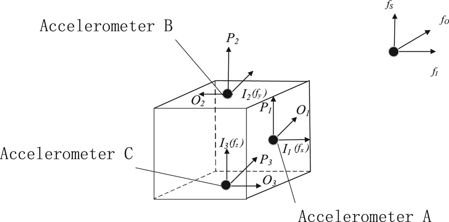
The IMU can be visualised as a cube: the three accelerometers inside it are fixed on the positional platform and are located as shown in Figure 2, at the bottom, the side and the back of the cube, and the orientation of each axis of the accelerometer in the INS is shown in Figure 2. In Figure 2, ‘I’ represents the input axis of the accelerometer, ‘O’ the output axis of the accelerometer and ‘S’ the spiral axis of the accelerometer.
Internal schematic diagram of accelerometer combination

3. Calibration principle of centrifuge norm-observation method for calibration equipment
3.1 Principle of norm observation method
The nominal form of IMU's input-specific forces in the static condition of the gravitational field is expressed as (Lötters et al., Reference Lötters, Schipper, Veltink, Olthuis and Bergveld1998):

in which $\boldsymbol{C}_{\boldsymbol{b}}^{\boldsymbol{n}}$ is the directional cosine matrix from the carrier system to the navigation system, ${{\boldsymbol{g}}^{\boldsymbol{n}}}$
 is the gravity acceleration and ${\boldsymbol{f}}_{\boldsymbol{g}}^{\boldsymbol{b}}$
 is the input-specific force in the three directions of the gravitational field.
By using the norm-observation method, the modes on both sides of Equation (1) are taken respectively, and the results can be written as:

It can be seen from Equation (2) that the expression of the nominal form is fixed and known in static conditions.
Similarly, when the high-precision centrifuge rotates, the object is only affected by gravity and centripetal acceleration, but the input specific forces of the accelerometer on the centrifuge can be expressed as:

in which ${\boldsymbol{A}^n}$ is the centripetal acceleration provided for the centrifuge, ${{\boldsymbol{f}}^{\boldsymbol{b}}}$
 is the input-specific forces of three directions, ${{\boldsymbol{f}}^{\boldsymbol{b}}}= {\left[ {\begin{array}{*{20}{c}} {f_x^b}& {f_y^b}& {f_z^b} \end{array}} \right]^\textrm{T}}$
 , $f_x^b$
 is the input-specific force of acceleration A, $f_y^b$
 is the input-specific force of acceleration B, and $f_z^b$
 is the input-specific force of acceleration C.
By using the norm-observation method, the modes on both sides of Equation (3) can be expressed as:

It can be seen from Equation (4) that when the centrifuge calibrates the accelerometer combination, the combination of the input-specific forces of the three directional accelerometers is equal to the combination of centripetal acceleration and gravity acceleration. This process can be further expressed as:

In Equation (5), $A= {\omega ^2}R$ , $\omega$
 is the rotation angular velocity of the centrifuge and R is the nominal value of the centrifuge.
When the coefficients of the error model to be calibrated are determined, the output value of the accelerometer is positively correlated with its input specific force. Therefore, in the actual calibration process, by obtaining the input specific force of the accelerometer at certain determined positions, and then obtaining the output value of the accelerometer, the error model coefficients of the accelerometer can be identified through the equation of the model observation method.
3.2 Model of accelerometer
According to the 2009 IEEE standard, the input specific force of IMU on the static condition of gravitational field satisfies

where ${{\boldsymbol{a}}_i}$ is the acceleration along sensor IA, ${{\boldsymbol{a}}_c}$
 is the centripetal acceleration of the centrifuge, ${\boldsymbol{\varPhi }_{{\boldsymbol{T}_{0}}}}$
 is the mount deflection angle, ${\boldsymbol{g}}$
 is the local value of gravity acceleration, and ${\boldsymbol{C}_{\boldsymbol{d}}}$
 is the deflection coefficient (angle/${{\boldsymbol{a}}_c}$
 ).
By transposing the term, Equation (6) can be expressed as:

Equation (7) only takes the installation misalignment angles of the centrifuge into consideration to express ${{\boldsymbol{a}}_c}$ , ignoring the mount-deflection angle of ${\boldsymbol{a}}_c^\textrm{2}$
 . When the centripetal acceleration of the centrifuge is expressed by the specific force, considering different kinds of centrifuge errors (including the whole mount-deflection angle of ${{\boldsymbol{a}}_c}$
 and ${\boldsymbol{a}}_c^\textrm{2}$
 ), considering the first-term and second-term error model coefficients, the error model of the accelerometer is:

in which ${{\boldsymbol{\varphi}}_{\boldsymbol{a}}}= {\boldsymbol{S}_{\boldsymbol{a}}}{\boldsymbol{\varPhi }_{\boldsymbol{a}}}$ , ${{\boldsymbol{S}}_{\boldsymbol{a}}}= \left( {\begin{array}{*{20}{c}} {{S_{ax}}}& 0& 0\\ 0& {{S_{ay}}}& 0\\ 0& 0& {{S_{az}}} \end{array}} \right)$
 is the scale factor, ${\boldsymbol{\varPhi }_{\boldsymbol{a}}}= \left( {\begin{array}{*{20}{c}} 1& { - \gamma_{xz}^a}& {\gamma_{xy}^a}\\ {\gamma_{yz}^a}& 1& { - \gamma_{yx}^a}\\ { - \gamma_{zy}^a}& {\gamma_{zx}^a}& 1 \end{array}} \right)$
 is the installation error coefficient, $\gamma _{xz}^a$
 and so on is the installation misalignment between the added table coordinate system and the carrier coordinate system, ${{\boldsymbol{K}}_{\boldsymbol{a}}}= {\left[ {\begin{array}{*{20}{c}} {{K_{ax}}}& {{K_{ay}}}& {{K_{az}}} \end{array}} \right]^T}$
 is the coefficient of quadratic term, ${{\boldsymbol{D}}_{\boldsymbol{a}}}= {\left[ {\begin{array}{*{20}{c}} {{D_{ax}}}& {{D_{ay}}}& {{D_{az}}} \end{array}} \right]^T}$
 is the output value of accelerometer, ${{\boldsymbol{B}}_{\boldsymbol{a}}}= {\left[ {\begin{array}{*{20}{c}} {{B_{ax}}}& {{B_{ay}}}& {{B_{az}}} \end{array}} \right]^T}$
 is bias of the three accelerometers, ${{\boldsymbol{d}}_{\boldsymbol{a}}}= {\left[ {\begin{array}{*{20}{c}} {{d_{ax}}}& {{d_{ay}}}& {{d_{az}}} \end{array}} \right]^T}$
 is the measurement error, and ${\boldsymbol{K}_{\boldsymbol{a}}}$
 is the deformation of ${\boldsymbol{C}_{\boldsymbol{d}}}$
 (under the force output conditions).
The error model decomposition form of the accelerometer can be established by substitution, as in:

4. A combined method for calibrating accelerometers using norm-observation
By simplifying Equation (9) and ignoring the higher-order infinitesimal terms, the error model coefficients can be obtained as follows:

In which,

Equation (10) is a quadratic equation of the input specific forces of three accelerometers. By using the extract roots formula of equation, we can obtain the expression of the input-specific forces. Because the input-specific force is positive, any negative ones should be excluded. The expression of the input specific forces is calculated as:

It can be seen from Equation (12) that the input-specific forces of the three accelerometers is related to ${(1 - 4{K_a}\Delta )^{0.5}}$ . This expression is not easy to factorise in the process of parameter identification, so it is considered to expand Equation (12) by the Taylor expansion formula. According to the numerical simulation, when the Taylor formula is expanded to the third term, the deviation between the error and the true value of the input-specific forces is less than 10−4. This result satisfies the requirement of the output accuracy of the accelerometer, so the quadratic term coefficient of the expansion is satisfactory only when the Taylor formula is expanded to the third term, and the calculation results are:

When measured in the gravitational field, taking Equation (13) into Equation (5), ignoring high-order infinitesimal in the expansion after the substitution and the influence of the installation misalignment, the result can be obtained:

In which ${K_x} = {K_{ax}}S_{ax}^{ - 1}{B_{ax}}$ , ${K_y} = {K_{ay}}S_{ay}^{ - 1}{B_{ay}}$
 ,${K_z} = {K_{az}}S_{az}^{ - 1}{B_{az}}$
 . By simplifying Equation (14), we can obtain:

In Equation (15),

According to Equation (15), when giving different test positions to the accelerometer combinations in the calibration process, the output of accelerometers can be obtained. Usually, the number of test positions: $N \ge 4n + 2$ , n is the number of quasi-identification coefficients. In Equation (15), there are 19 parameters to be identified, so the number of test positions N is at least 78, and the equations can be obtained. These equations can be expressed as:

In Equation (17),

By using the least-squares algorithm, the calculation formulas of 19 parameters to be identified are:

It can be seen from the relationship between the coefficients of the observation Equation (18):

Assuming ${M_1}= \frac{{{C_{41}}}}{{{C_{31}}}} \cdot \frac{{{C_{11}}}}{{{C_{21}}}}$ , ${M_2}= \frac{{{C_{42}}}}{{{C_{32}}}} \cdot \frac{{{C_{12}}}}{{{C_{22}}}}$
 , ${M_3}= \frac{{{C_{43}}}}{{{C_{33}}}} \cdot \frac{{{C_{13}}}}{{{C_{23}}}}$
 , we can obtain:

The values of ${K_x}$ , ${K_y}$
 and ${K_z}$
 can be obtained, and then the scale factors of the three accelerometers can be obtained:

The quadratic term coefficients of the three accelerometers are:

The bias of the three accelerometers is:

So far, the expression of the coefficient to be calibrated in the error model coefficients of Equation (8) is shown in Equations (21)–(23).
In an actual calibration, according to the calculation process of Equations (18)–(23), by setting multiple positions and collecting the outputs of three accelerometers on different positions, the overall calibration of the accelerometer combination can be completed. Particularly, by using the norm-observation method, the calibration of the quadratic coefficient of the accelerometer is realised.
5. Experimental simulation and error analysis
Let the radius R of a boomed precision centrifuge, shown in Figure 1, be 1 m; each attitude error of the centrifuge be 1 × 10⁻³(1 × 10⁻³ rad = 206 ⋅ 3′′); and the latitude φ of the calibration position be N 39 ⋅ 0°(Tianjin). The value of g is 9 ⋅ 8011 Kg/N.
Generally speaking, the output form of accelerometer is current, voltage and other electrical signals. In this paper, voltage (unit: volt) is mainly used to represent the output value of the accelerometer.
The scale factors of the accelerometer to be selected are:

The bias of the accelerometer is respectively shown as follows:

The quadratic term coefficients of the accelerometer are, respectively:

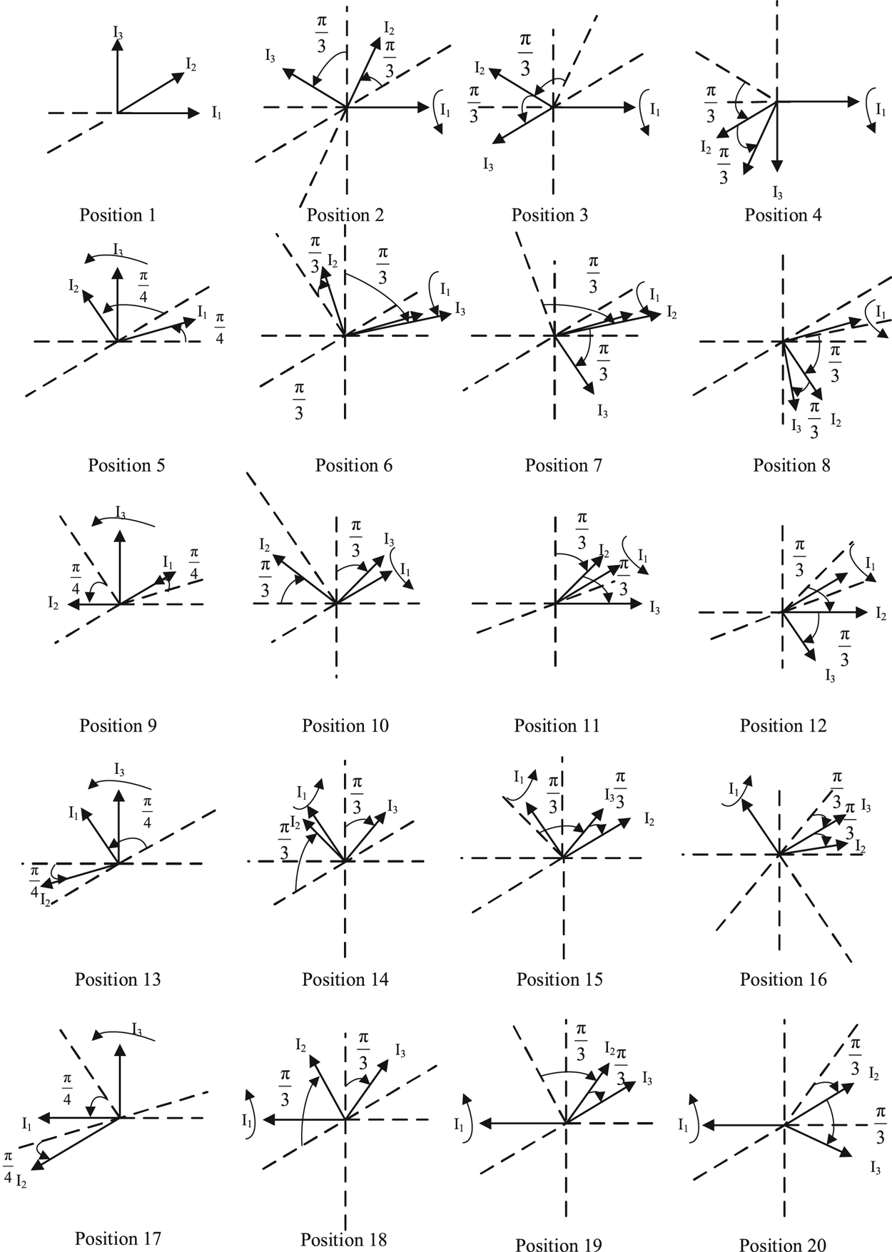
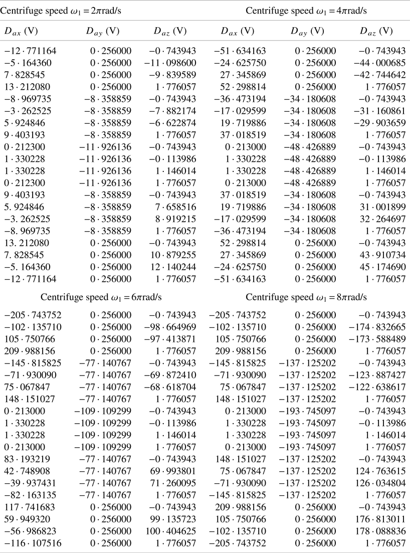
To verify the accuracy of the method in the simulation, a random error of around 10−5 V is added to each output to simulate the impact of measurement or environmental error on the outputs of the accelerometers. The number of collecting and testing positions N is 80; therefore, $N\mathrm{\ > }\textrm{78}$ satisfies the requirements. The specific schematic diagram of the three-axis accelerometer is shown in Figure 3, and the specific output of each accelerometer in the simulation process is listed in Table 1.
Schematic diagram of the input axis of the three accelerometers at 20 positions

Actual output of three accelerometers at different centrifuge speeds at 20 positions

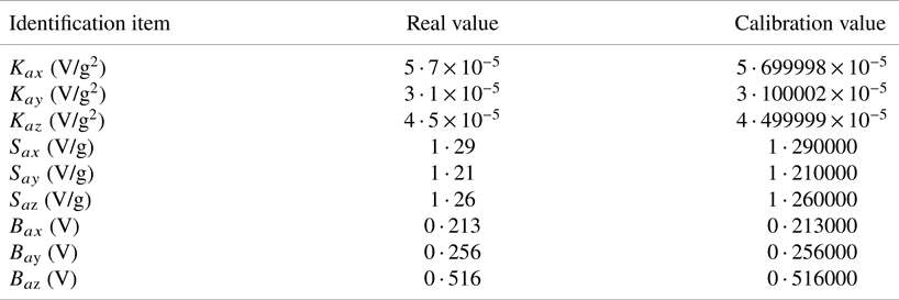
According to Equations (10)–(23), the specific values of bias, scale factor and quadratic coefficient of three accelerometers can be obtained (without considering installation misalignment and rod-arm error). The simulation calibration results are listed in Table 2
Results of simulation of calibration of accelerometer combinations

.
5.1 The installation misalignment analysis
By substituting Equation (11) into the Equations (12)–(14), the corrected input specific force expression with error term can be obtained as:

In which ${\varepsilon _1}= \gamma _{xz}^aS_{ay}^{ - 1}({D_{ay}} - {B_{ay}}) - \gamma _{xy}^aS_{az}^{ - 1}({D_{az}} - {B_{az}}),$


Note that the installation misalignment are largely influencing the terms ${C_{11}}$ , ${C_{12}}$
 and ${C_{13}}$
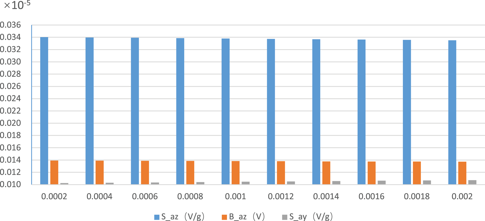
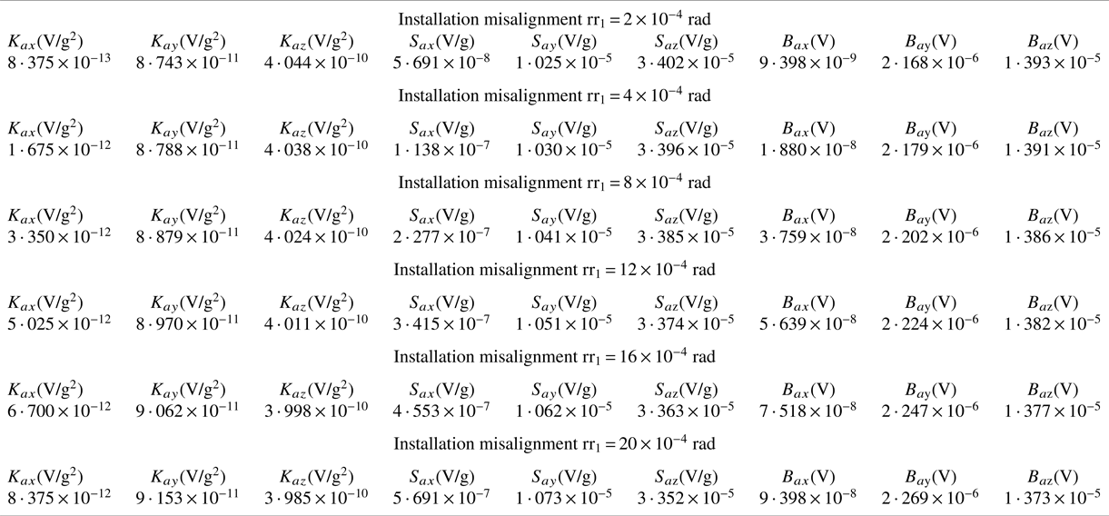
 of Equation (16), and the calibration results of each coefficient are influenced by the application of Equations (19)–(24) to calculate the coefficients of each error model. Let the installation misalignment of three accelerometers vary from 2 × 10⁻⁴ rad to 10 × 10−4 rad. When calculating the influence of the installation misalignment on the scale factor, quadratic coefficient and bias, the most noticeable results are shown in Figure 4, and their actual values are listed in Table 3.
Partial impacts of error in the installation angle on the calibration accuracy of the quadratic coefficients of the accelerometer

Actual value of three accelerometers about the installation misalignments

With the increase of the installation misalignment, the influence on the calibration accuracy of all error model coefficients increases. As seen from Figure 4 and Table 3, the misalignment has the most significant influence on the scale factor of the three accelerometers, the second on the bias. From the point of view of the influence, the influence of the installation misalignment is far less than the accuracy requirement of the error model coefficient. Therefore, in an actual calibration process, the influence of installation misalignment error on the calibration accuracy of error model coefficients can be negligible.
5.2 Rod-arm error analysis
The inertial combination shown in Figure 1 contained three accelerometers, and the internal installation of the inertial combination is shown in Figure 3. In Figure 3, three accelerometers are located at the bottom, side and back, respectively, and the orientation of each axis of each accelerometer is given. I is the input axis, O is the output axis and P is the pendulum axis.
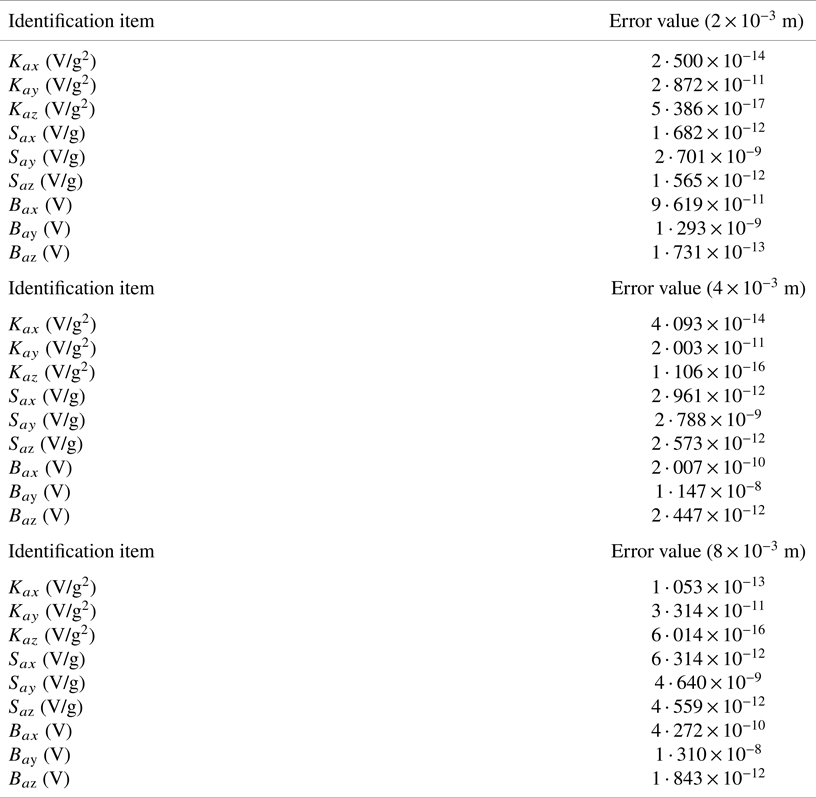
As can be seen from Figure 2, due to the different installation positions of the three accelerometers, the rotation radius of the centrifuge will be different. There is a certain error in the sensitive input specific force of accelerometer B, accelerometer C and accelerometer A. Therefore, it will influence the size of ${\tilde{A}^2}$ . Let the arm-error value be 2 × 10⁻³ m, 4 × 10⁻³ m, and 8 × 10⁻³ m; the influence of the arm error on the scale factor, quadratic coefficient and bias is calculated by using Equations (19)–(24), as listed in Table 4.
The influence of rod arm error on the coefficients of the error model

As can be seen from Table 4, with the increase of rod-arm error, the error value increased or reduced significantly at the same time. Above the rod-arm errors, with ${K_{ay}}$ and ${B_{a\textrm{z}}}$
 expected, other rod-arm errors are increasing.
6. Conclusions
In this paper, the norm-observation method was used to simultaneously calibrate the error model coefficients, especially including the scale factor and quadratic coefficients, and a combination of three accelerometers in a boomed centrifuge was designed. The error sources of the accelerometers that affect the calibration precision of IMU were analysed, and the corresponding coordinate system was established. The main tasks were as follows:
(1) The calculation was simplified by using the Taylor series to expand nonlinear terms. Twenty positions were designed, and three angular rates of the main axis were adopted.
(2) A method for the overall calibration was designed, combined with the accelerometer error model. The quadratic coefficient was calculated accurately using the homogeneous transformation method.
(3) A 20-position calibration method is validated through simulation. The accelerometer's installation-angle and rod-arm errors had little influence on the calibration accuracy of its quadratic coefficient. This accuracy can be improved by compensating for the INS errors.
The proposed method provides a theoretical basis and a reference value for calibrating an accelerometer combination and can improve the accuracy of INS calibration.
Competing Interests
We declare that we have no financial and personal relationships with other people or organisations that can inappropriately influence our work, there is no professional or other personal interest of any nature or kind in any product, service and/or company that could be construed as influencing the position presented in, or the review of, the manuscript entitled.