I. INTRODUCTION
A lot of scientific researchers worldwide are making great efforts to develop new energy materials to substitute fossil fuels. However, until now, fossil fuels are still the main energy sources and generate gigatons of carbon dioxide every year. Carbon dioxide is the main component of greenhouse gases, which would change severely the climate of the environment at high concentrations. The separation of CO2 (3.3 Å) from N2 (3.64 Å) is of great interest. Furthermore, the CO2 separation from CH4 is important in terms of natural gas processing because CO2 molecules cause the decrease of natural gas heat value and corrosion of pipeline. The separation of CO2 from CH4 (3.8 Å) is also an important aspect with a similar significance. Membrane separation of CO2 is supposed to be an efficient technique among the various feasible ways, due to its relatively low-energy consumption and ease of processing.
Zeolite is considered as a kind of promising material to fabricate membrane, owing to their uniform channels,Reference Guo, Zhu, Li, Zou, Yin, Yang, Qiu and Xu1–Reference Xomeritakis, Lai and Tsapatsis3 micropores catalytic activity,Reference Haag, Hanebuth, Mabande, Avhale, Schwieger and Dittmeyer4,Reference Jeong, Sotowa and Kusakabe5 low dielectric constant,Reference Wang, Mitra, Wang, Huang and Yan6,Reference Liu, Lew, Sun, Cai, Wang, Kloster, Boyanov and Yan7 and excellent chemical and thermal stability.Reference Cai, Sun, Chen, Munoz, O'Neill, Beving and Yan8 Among various zeolites, MFI with unique pore sizes (0.53 × 0.56 nm straight channels along b-axis, 0.51 × 0.55 nm sinusoidal channels along a-axis) is considered as a good choice to form membranes for separating many industrially important organic molecules. There are a great number of reports about MFI membranes. The research content and key point are diverse which mainly focus on three aspects: (i) controlling the crystal orientation of MFI membranes.Reference Li, Peng, Wang and Yan9–Reference Zhang, Fuji and Takahashi15 The preferred orientation of the membrane is often beneficial for various potential applications such as gas separation,Reference Lai and Tsapatsis16,Reference O’Brien-Abraham, Kanezashi and Lin17 chemical sensors,Reference Kikuchi, Yamashita, Hiromoto, Ueyama and Matsukata18,Reference Vilaseca, Coronas, Cirera, Cornet, Morante and Santamarıa19 membrane reactors,Reference Hedlund, Schoeman and Sterte20 and optical devices.Reference Sun, Zhu, Yin, Chen, Cui and Qiu21 The b-oriented MFI membrane is mostly investigated because the channel along this direction is shortest and straight, providing an easy passage of gas molecules and contributes to form a membrane with high permeability. (ii) Investigating gas permeation and separation characteristics of the MFI membranes. The factors affecting the gas permeation properties of MFI membranes have widely been considered, such as different Si/Al,Reference Noack, Kölsch, Caro, Schneider, Toussaint and Sieber22 the permeation temperature and pressure,Reference Kanezashi and Lin23,Reference Poshusta, Noble and Falconer24 the calcination rate,Reference Jareman, Andersson and Hedlund25 the pore structure of the substrate,Reference Deng, Nicolas, Daramola, Sublet, Schiestel, Burger, Guo, Giroir-Fendler and Pera-Titus26 and the lattice substitution by other elements.Reference Li, Tuan, Falconer and Noble27–Reference Tuan, Li, Falconer and Noble30 (iii) Discovering the mechanisms of the permeation and separation of the MFI membrane. There are five widely accepted separation mechanismsReference Shekhawat, Luebke and Pennline31−Reference Javaid33: (a) Knudsen diffusion, where the molecules collide with the pore wall more frequently compared with the collisions among molecules. It is significant when the mean free path of the gas molecules is larger than the pore size. (b) Molecular diffusion, where the collisions of molecule to molecule are primary, and it predominates when the mean free path of the gas molecules is smaller than the pore size. (c) Surface diffusion, which occurs when the permeating species exhibit a strong affinity for the membrane surface and adsorb along the pore walls. (d) Capillary condensation. (e) Molecular sieving. Generally, the permeability of the MFI membranes for the separation of CO2 from a binary mixture is governed by surface diffusion.Reference Guo, Zhu, Li, Zou, Yin, Yang, Qiu and Xu1,Reference Kanezashi and Lin23,Reference Bernal, Coronas, Menendez and Santamaria34
There are several strategies developed for the synthesis of the MFI membranes, including seeded growthReference Xomeritakis, Lai and Tsapatsis3,Reference Bernal, Xomeritakis and Tsapatsis35–Reference Sandström, Sjöberg and Hedlund37 and in situ method.Reference Wang and Yan11,Reference Wang and Yan38,Reference Lee, Funke, Noble and Falconer39 Although the seeded growth method could separate and control the nucleation and crystal growth processes, but it is difficult to get an uniform seed layer.Reference Li, Yan and Wang12 On the contrary, the in situ method without the seeding process is more simple and effective to produce significant adhesion to many kinds of substrates with complex shapes.Reference Wang and Yan11 Among various substrates, hollow fiber geometry has long been a good choice to ameliorate the performance of membrane-based separation processes because of its low cost and large surface/volume ratios.Reference Alshebani, Pera-Titus, Landrivon, Schiestel, Miachon and Dalmon40 Moreover, α-Al2O3 hollow ceramic fifibers (HCFs) can provide aluminum source. The participation in the framework of the MFI crystal of Al from the substrate is able to increase the adhesion between the membrane and the substrate.
To the best of our knowledge, five papersReference Deng, Nicolas, Daramola, Sublet, Schiestel, Burger, Guo, Giroir-Fendler and Pera-Titus26,Reference Deng, Nicolas, Guo, Giroir-Fendler and Pera-Titus28,Reference Alshebani, Pera-Titus, Landrivon, Schiestel, Miachon and Dalmon40–Reference Pera-Titus, Alshebani, Nicolas, Roumégoux, Miachon and Dalmon42 have reported the fabrication of MFI membranes on alumina HCFs with the same synthesis method, pore-plugging synthesis. In addition, there is no report about the separation of CO2/CH4 with the MFI membrane supported by α-Al2O3 hollow fifibres. In this work, we have successfully fabricated an entirely compact and continuous MFI membrane on HCFs by in situ hydrothermal synthetic method. The as-prepared MFI membranes are measured by single and binary gas permeation under different permeation temperature and pressure. The results show that the MFI membranes exhibit high CO2 selectivity from N2 and CH4.
II. EXPERIMENT
A. Materials
HCFs (internal diameter is 2.5 mm, external diameter is 3.5 mm, the length is 30 mm, pore size of the inside layer: 200 nm, and pore size of the outside layer: 1 µm, porosity: 30–40%, Hyflux membrane Co.) were used as supports. Tetraethylorthosilicate [TEOS > 99%(GC)] was supplied by Beijing Chemical Plant. Tetrapropylammonium hydroxide (TPAOH 1 mol/L aqueous solution) was purchased from Tokyo Chemical Industry Co. Ltd. (Tokyo, Japan).
B. Pretreatment of HCFs
Prior to use, the HCFs were activated as follows: first calcined under 773 K for 12 h to remove the organics from the pores of the support and then cleaned thoroughly with deionized water under ultrasonication for three times. After that, they were sequentially treated with piranha solution [H2SO4/H2O2 = 3/1, v/v, H2SO4(18.4 mol/L), H2O2(30%W)] at 363 K for 8 h to introduce more hydroxyl groups to the substrate surface. Lastly, the substrates were washed with deionized water several times until the pH value of the water was about 7, and then dried at 353 K overnight.
C. Synthesis of the MFI membrane
The synthesis reaction solution was prepared in the molar ratio of TEOS:TPAOH:H2O = 1:0.35:100. To prepare the solution, TEOS should be added slowly to the mixture of water and TPAOH under stirring until it became clear. Then the pretreated HCFs were filled with a solution of water and glycerol (1:1 mass ratio), and both sides of the fiber were sealed with Teflon tape. This is an efficient method to stop the penetration of synthesis solution into the substrate by suppressing the crystal growth on the inner side, which is helpful to fabricate a membrane with high gases permeance.Reference Chen, Li and Yang43
Then the substrate was placed vertically in a Teflon-lined stainless-steel autoclave. The reaction solution was poured into the autoclave carefully, making sure that the reaction solution overflows the support. And then the autoclave was sealed and subjected to a hydrothermal treatment at 443 K for 10 h. After crystallization, the membrane was taken out and thoroughly washed with deionized water several times, dried at 353 K overnight. The dried membrane was calcined at 773 K for 2 h to remove the organic template. Ramp heating rate of 0.2 K/min was used throughout the calcination procedure to avoid the cracking caused by the different thermal expansion coefficients between the zeolite membrane and the alumina support.
D. Characterization
The crystalline structures of MFI crystals and membrane were determined by the x-ray diffraction (XRD) measurements using a Riguku D/MAX2550 diffractometer (Tokyo, Japan) with Cu Kα radiation (λ = 1.5418 Å). The morphology of the MFI membrane was monitored by a fifield-emission scanning electron microscope (FE-SEM: JEOS JSM6700F, Tokyo, Japan). X-ray photoelectron spectroscopy (XPS) was applied to characterize the element distribution among the different depths of the membrane.
The membrane pretreated/activated, as described above, was sealed in a membrane module which has been introduced clearly in our early reportReference Guo, Zhu, Li, Zou, Yin, Yang, Qiu and Xu1 and the separation tests were performed. The flux of the gas was measured by a soap-fifilm flow meter. The flow rate of the sweep gas Ar was controlled at the rate of 50 mL/min. The feed flow rate was set to 100 mL/min for single gas measurements. The total volumetric flow in the feed for binary gas measurements was 100 mL/min with each gas of 50 mL/min. The mixture gases in the feed side were introduced into the inner side of HCFs from the inlet and the feed pressure was measured by a pressure gauge, while the outlet was connected with a vacuum valve. By controlling the vacuum valve, we could regulate the permeation pressure. The permeate components through the membrane were taken by Ar into an on-line HP6890 gas chromatograph (Waltham, MA).
III. RESULTS AND DISCUSSION
A. Characterization of the MFI membrane
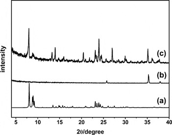
It is very hard to characterize the crystal membrane in situ by XRD because the membrane is too thin and on the tube substrate.Reference Xu, Yang, Liu, Lin, Stroh and Brunner44 So we scaled the crystals off from the outside surface of the substrate and examined this powder using XRD. As shown in Fig. 1, the peaks in the diffraction pattern of the powder coincides very well with that of the MFI structure, implying that the membrane consists of highly crystalline MFI crystals.
XRD Patterns of (a) simulated MFI structure from calculation; (b) HCFs; (c) as-synthesized HCFs supported MFI membrane after calcination.

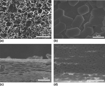
The morphology of the membrane was characterized by scanning electron microscope (SEM). As shown in Fig. 2(a), the surface of the raw hollow fiber is rough. The large pores on HCFs cannot be expected to have any possibility to separate the mixed small-molecule gases. The top view of the synthesized MFI crystalline layer is shown in Fig. 2(b). It is demonstrated that MFI crystals with a size of about 1–2 µm thoroughly covered the outside surface of the substrate and formed a multilayer. The intergrowth of bottom crystals generated an entirely compact and continuous MFI membrane without any pinholes or cracks. Figures 2(c) and 2(d) are the cross-sectional SEM images, while the interface between the membrane and the support cannot be clearly identified. The reason may be that the aluminum in the support participates in the formation of the MFI crystal framework.
SEM images of (a) the HCFs, (b) top-view and (c, d) the cross-section of the outside surface of the MFI membrane after calcination.

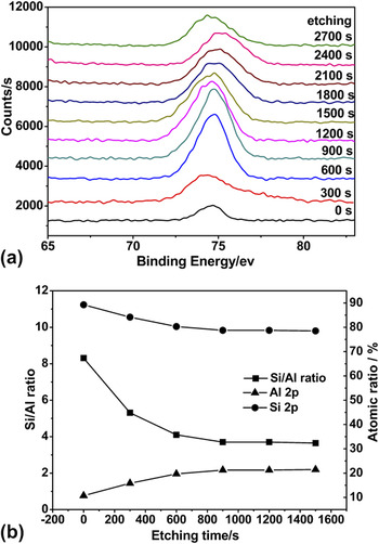
XPS was performed to determine the composition of different depths of the MFI membrane. The core-level Al 2p XPS spectra of the MFI membrane after etching from the surface for various times are shown in Fig. 3(a). It is worthwhile to note that the peak width at half height of Al 2p gets narrower when the etching time decreases from 600 to 1500 s. The sharper peaks might indicate a more ordered structure.Reference Xu, Khor, Sui and Chen45 Considering that the etching time is proportional to the depth of the membrane, aluminum in the MFI membrane would be in a more ordered state relative to that in the substrate. The results of the XPS depth profile for the MFI membranes are presented in Fig. 3(b). The atomic ratio of silicon of the MFI membrane decreased with an increase of etching time but that of the aluminum increased, on the contrary. Meanwhile, the Si/Al ratio decreased with an increase of the depth of the membrane. Based on the above observations, it can be concluded that aluminum from the substrate has taken part in the formation of the MFI membrane which also explains why the interface between the membrane and the substrate cannot be clearly identified.
(a) Al 2p spectra of the XPS after different etching times from the HCFs supported MFI membrane surface. (b) XPS profiles of the as-synthesized HCFs supported MFI membrane.

B. Gas permeation
1. Permeation of single gas
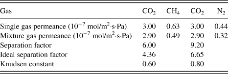
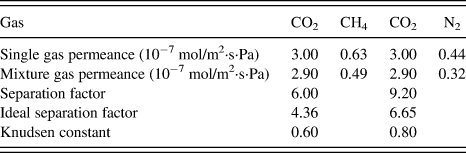
The MFI membranes were tested for permeation using CH4, N2, and CO2 as single gases. The permeation results under room temperature (293 K) and atmospheric pressure are summarized in Table I. As shown in Table I, the membrane exhibits remarkably higher CO2 permeance compared with other gases (CH4 and N2). Additionally, the permeances decrease with a sequence of CO2 > CH4 > N2 which is not in accordance with the decreasing trend of their molecular weights. This observation sheds light on the importance of the effect of adsorption in the gas permeation. We can note that the ideal selectivity is much higher than the Knudsen constant. This means that the membrane possesses good quality and is suitable to separate these two kinds of gas mixtures.
Single and mixture gas permeances (mol/m2·s·Pa) and separation factors for the HCFs supported MFI membrane at 298 K and a pressure drop of 100 kPa, and the volume ratio for mixture gas systems is 1:1.
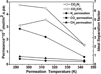
Generally, the permeance can be influenced by temperature. Figure 4 illustrates the single gas permeances and separation factors through MFI membranes as a function of temperature. It is demonstrated that the permeances of CO2 decrease quickly from 2.85 × 10⁻⁷ to 6 × 10⁻⁸ mol/m2·s·Pa with increasing temperature. The permeances of N2 and CH4 also show a continuous decrease from 293 to 343 K, but their amplitude of variations are different, giving rise to a decrease of the ideal separation factors. It is found that the values of the ideal factor are still considerably higher than their Knudsen separation factors (0.6 and 0.8). So the membranes are expected to have the possibility to selectively separate CO2.
The single gas permeances and ideal separation factors of the HCFs supported MFI membrane as a function of temperature at a pressure drop of 1.0 × 10⁵ Pa.

2. Permeation of binary gas mixture
Gas separation studies of binary gases (CO2/N2 and CO2/CH4) with an equal volume ratio were implemented. As shown in Table I, the MFI membrane shows high efficiency of CO2 separation from the gas mixtures of CO2/N2 and CO2/CH4, the separation factors of CO2/CH4 and CO2/N2 are 6.0 and 9.2 respectively, which far exceed the Knudsen constants 0.6 and 0.8 respectively. The separation factor of our MFI membrane for CO2/N2 is higher than those of other reported MFI membranes supported by α-Al2O3 HCFs (below 8).Reference Deng, Nicolas, Daramola, Sublet, Schiestel, Burger, Guo, Giroir-Fendler and Pera-Titus26 The CO2 permeance is approximately the same for both single and binary gas permeance systems (3 × 10⁻⁷mol/m2·s·Pa) which means that the permeance of CO2 would not be severely influenced by CH4 and N2, whereas the N2 and CH4 permeances greatly decrease by the feed containing CO2. That could explain that the ideal separation factors of CO2 over CH4 and N2 (4.4 and 6.6) are less than the separation factors (6 and 9.2). The results suggest that the membrane provides good selectivity toward CO2.
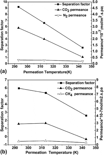
To investigate the thermal behaviors of the MFI membranes, the permeations at different temperatures (from 293 to 343 K) were also evaluated (Fig. 5). As a result of the single gas permeation, the CO2, CH4, and N2 permeances decreased noticeably when the permeation temperature increased from 293 to 343 K. A declining trend of CO2/N2 and CO2/CH4 separation factors is observed accordingly. While under 343 K, the separation factors (2.17 and 2.15) are still higher than their respective Knudsen constants (0.8 and 0.6) which show that the membrane can be used in broad temperature ranges.
(a) CO2/N2 and (b) CO2/CH4 permeances and separation factors of the HCFs supported MFI membrane as a function of the permeation temperature at a pressure drop of 1.0 × 10⁵ Pa.

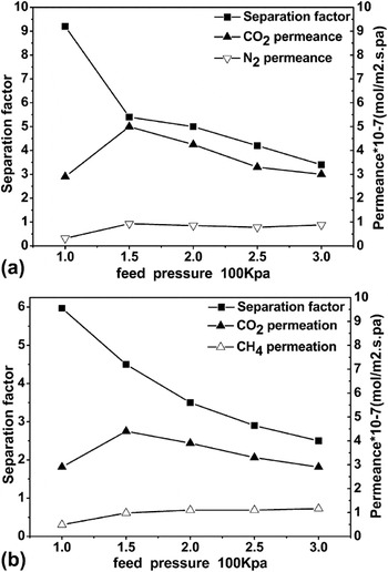
The mechanical stability of the membrane is also a very important parameter. So we carried out the CO2 separation tests by increasing the feed pressure from 1.01 × 10⁵ to 3 × 10⁵ Pa (Fig. 6). With the increase of the feed pressure, the permeances of CH4 and N2 increased slightly, however, the permeance of CO2 meets its maximum at 1.5 × 10⁵ Pa. It is shown that the separation factors decreased with the growth of feed pressure. Nevertheless, moderate separation factors (3.4 and 2.5) higher than their Knudsen constants (0.8 and 0.6) are still observed at a relatively high feed pressure (3 × 10⁵ Pa), which means that the MFI membrane possesses high mechanical stability.
(a) CO2/N2 and (b) CO2/CH4 permeances and separation factors of the HCFs supported MFI membrane as a function of the feed pressure at 298 K.

3. The speculation of the separation mechanism
Based on our gases separation results, we speculate the separation mechanism should be surface diffusion which means the permeance is governed by both diffusion and adsorption. Typically, the heat of adsorption of gases on most zeolites increases in this order CH4 < N2 < CO2.Reference Shekhawat, Luebke and Pennline31 This order is consistent with the electrostatic properties of each molecule. Carbon dioxide adsorbs the strongest because it has the strongest electrostatic quadrupolar moment of the three gases, which significantly contributes to its attraction to polar surfaces. So CO2 adsorbs more strongly on MFI channels than the other gases. The preferential absorbed CO2 molecules will form adsorption and desorption equilibrium and reduce the opening of the MFI crystal channels inhibiting the CH4 and N2 sorption from the mixture. Further, the effective pore size of MFI crystals (0.53 × 0.56 nm, 0.51 × 0.55 nm) does not allow two molecules to pass through simultaneously. Thus, once CO2 has diffused through the pores, the diffusion of CH4 and N2 molecules would be blocked. As a result, carbon dioxide molecules will preferentially permeate in CO2/N2 and CO2/CH4.
At higher temperatures, the competitive adsorption capacity of CO2 molecules decrease, which results in reducing the ability of CO2 to block adsorption sites for CH4 and N2 molecules. So the CO2 permeance decreases significantly. The CO2/N2 and CO2/CH4 mixtures are mainly separated by the differences in diffusivity. As a result, the constantly declining trends of separation factors were obtained. Under higher feed pressure, the diffusion rates and adsorptions are improved in different magnitudes among CO2, CH4, and N2. Consequently, the separation factors experience decreasing trends.
4. The durability of the MFI membrane
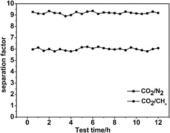
The reproducibility and durability of the membranes are important parameters for practical application. As shown in Fig. 7, the separation factors do not change obviously with small fluctuation over a 12 h period. The membrane can be also used repeatedly for at least 3 months, showing that the MFI membranes have outstanding stability and a broad application prospect.
CO2/N2, CO2/CH4 separation factors for the HCF supported MFI membrane over time at 298 K with a pressure drop of 1 × 10⁵ Pa.

IV. CONCLUSIONS
We have successfully prepared an MFI membrane on HCFs, using in situ method under hydrothermal conditions. As-prepared MFI membrane is evaluated for CO2 separation under different permeation temperatures and pressures. The experimental results show that the membrane exhibited high permeance (3 × 10⁻⁷mol/m2·s·Pa) and excellent permeation selectivity for CO2 over N2 and CH4. It also shows high thermal and mechanical stabilities. Moreover, the gas separation mechanism was briefly discussed. The preferred diffusion and competitive adsorption could be the essence in the selective permeations of gas mixtures. The membrane possesses excellent durability and reproducibility. Such high performance zeolite membranes possess the potential application prospect in the separation and recovery of CO2.
ACKNOWLEDGMENTS
We are grateful for the financial support of National Basic Research Program of China (973 Program, Grant No. 2012CB821700), Major International (Regional) Joint Research Project of NSFC (Grant No. 21120102034) and NSFC (Grant No. 20831002).