





Impact statement
This research reimagines glass as a bio-integrated material by developing bioreceptive porous glass scaffolds that support biological growth. It offers a transferable method for designing living interfaces that contribute to regenerative, multi-species architecture.
From purity to habitat: Glass reimagined
Can a material historically associated with inertness, sterility and impermeability be redesigned as a living architectural interface? This work develops porous glass scaffolds fabricated from recycled glass through controlled sintering, foaming and slumping, with the aim of supporting sustained biological growth. Here, glass is treated not simply as a transparent medium, but as an active material system that modulates moisture, light and biological inhabitation, which can participate in wider ecological processes within the built environment.
Across architectural history, glass has evolved from a handcrafted material into a standardised industrial surface associated with uniformity, clarity and purity. From the Crystal Haus to stained glass in churches, glass has always carried ideologies of purity through clarity and the control of light (Scheerbart and Taut Reference Scheerbart, Taut and Sharp1972). Early modernist architects, notably Mies van der Rohe and Pierre Chareau, explored the idea of spatial dematerialisation through transparency and reflection, echoing the theoretical lineage proposed by Paul Scheerbart. The modernist ideal of the transparent envelope continues to shape contemporary architecture, where recent explorations of glass are largely centred on maintaining clarity and transparency while adding technical functionalities, such as insulative properties, load-bearing glass or the integration of smart glass technologies and specialised coatings (Richards Reference Richards2012; Syrén Reference Syrén2023; Wiederhorn and Clarke Reference Wiederhorn and Clarke2022).
Despite its extensive use as a façade material, glass remains relatively underexplored within recent discussions of bioreceptivity and urban greening. Bioreceptivity marks a shift from the short-lived Anthropocene towards a longer-term Biocene, where human habitats coexist symbiotically with other species (Cruz and Beckett Reference Cruz and Beckett2016; Cruz and Parker Reference Cruz and Parker2022). However, biological growths on glass façades are often perceived as debris or contamination that conflicts with its perfection and visual purity.
In 2013, the BIQ Algae House demonstrated a system where glass façade panels were designed as photobioreactors for algae cultivation, producing heat and energy for the building’s occupiers, functioning closer to solar panels than to traditional windows or glazing (Roedel and Petersen Reference Roedel and Petersen2013). More recently, Ferrándiz-Mas et al. (Reference Ferrandiz-Mas, Bond, Zhang, Melchiorri and Cheeseman2016) and Giassia (Reference Giassia2022) have explored the making of porous tiles from recycled glass to support bioreceptivity of algae and moss. Recognising the potentials in glass architecture and bioreceptivity, this work challenges conventional glazing systems, reimagining glass architecture through the lens of the Bioscene. When other organisms are invited to live amongst human users, designs begin to embody ideologies beyond human-centric ones that have led to the extractive nature of architecture.
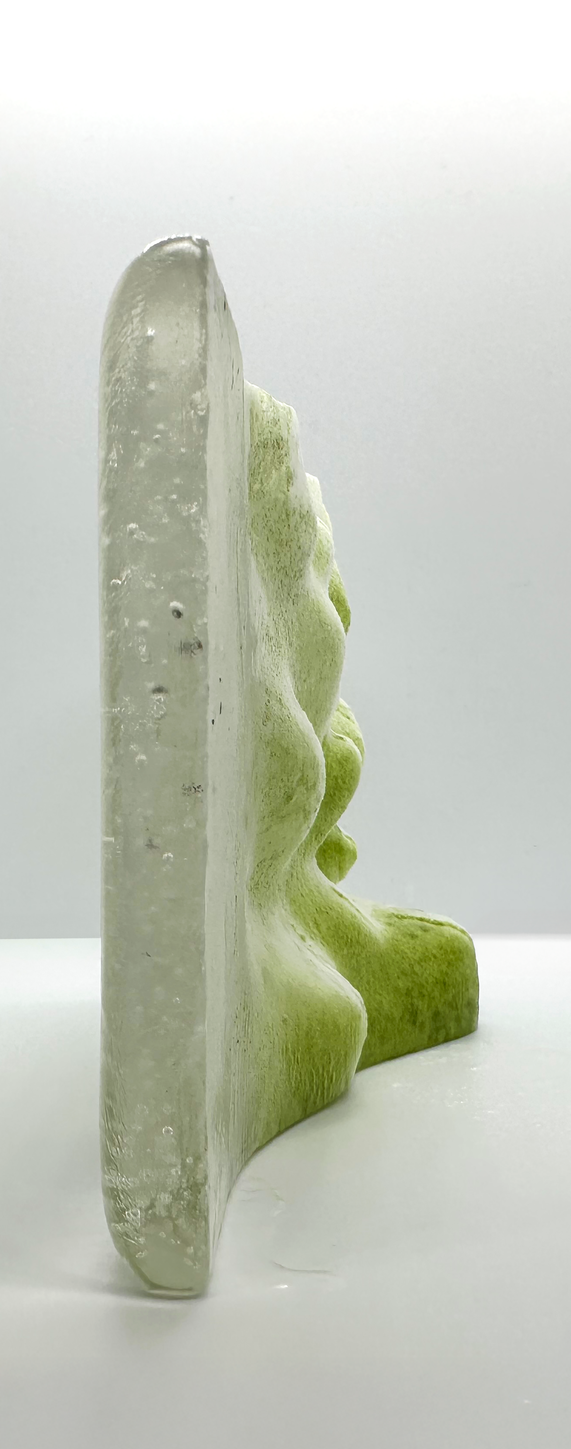
Glass as Habitat emerges from this repositioning of glass beyond its symbolism. Porosity, multiscalar pore networks and semi-translucency are used as design strategies to place glass in dialogue with environmental processes and living systems. Further explorations through material testing and façade-scale speculations examine patterned transparency and deep bioreceptivity (Cruz Reference Cruz2025) as conditions for photosynthetic communities. The façade becomes an “architectural bark” (Cruz and Beckett Reference Cruz and Beckett2016, 51), acting as a receptive interface that supports living organisms, supporting urban biodiversity and connecting architecture to wider ecological processes. Glass shifts from a “clean boundary” to a semi-translucent scaffold designed to invite growth, challenging the sterile transparency of modernism by embracing “imperfections” (Figures 1 and 3). Rather than maintaining surfaces through constant cleansing, the authors argue for moving beyond ideals of purity and perfection towards the “impure aesthetics” of ageing and heterogeneity. Maintenance, therefore shifts towards calibration, monitoring and care (Cruz and Beckett Reference Cruz and Beckett2016; Cruz and Parker Reference Cruz and Parker2022). The glass itself is not alive; instead, it becomes an interface for life by accommodating photosynthetic communities within carefully tuned microhabitats.
Prototype 1 porous glass morphology (1:1 scale), side view, showing a clear-to-foamed gradient, inoculated with Chlorella vulgaris (C. vulgaris) and observed at week 9 under uncontrolled indoor conditions.

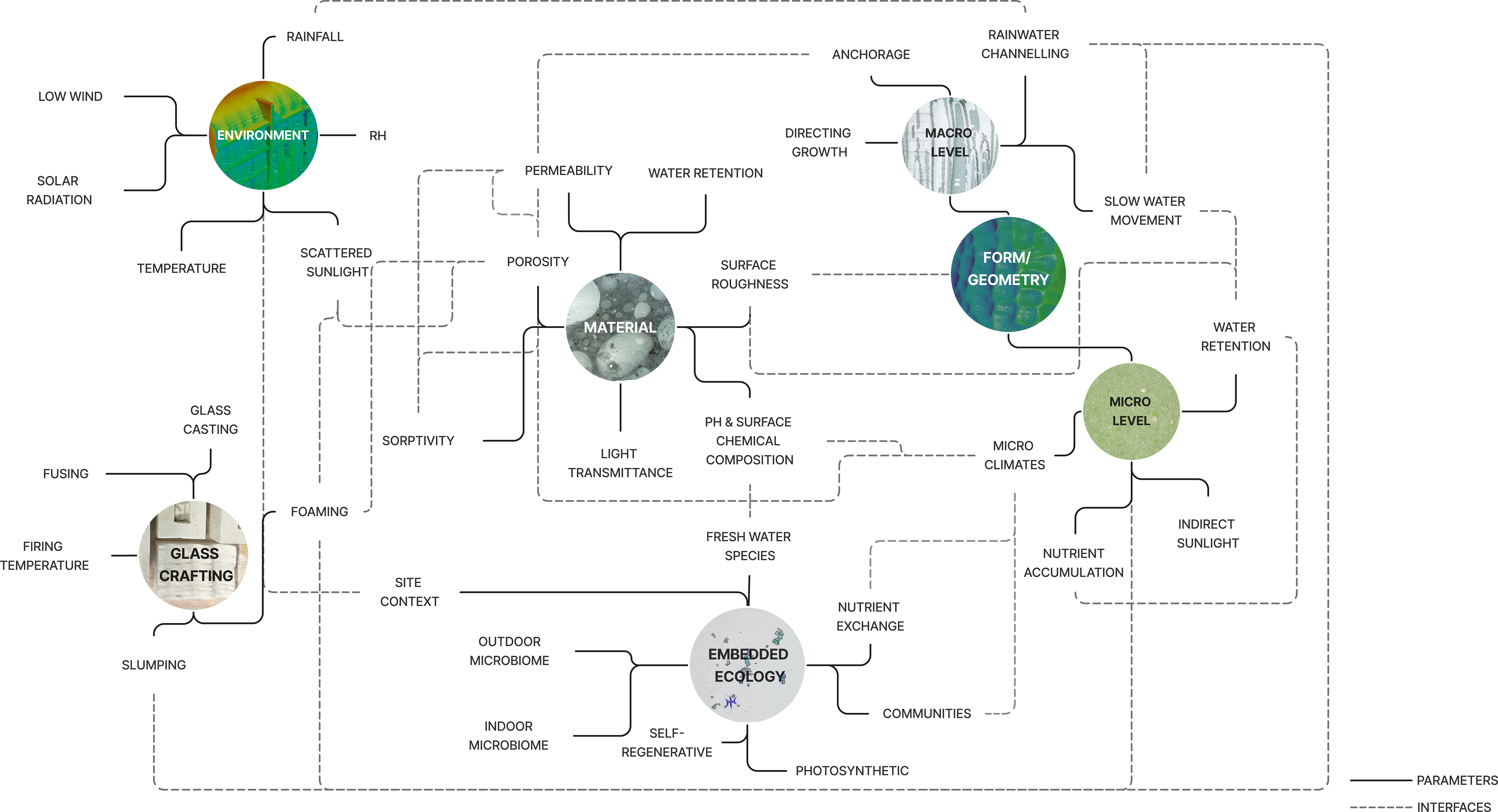
Research map of the interdisciplinary methodology, showing key parameters (solid lines) and interfaces (dashed lines) across environment, material, geometry, microclimate and embedded ecology.

Figure 2. Long description
The diagram presents the project methodology as a network of feedback loops. Main circular nodes include environment, glass crafting, material, macro level, form/geometry, micro level, and embedded ecology. Solid lines indicate parameters, while dashed lines indicate interfaces. Environmental inputs such as rainfall, low wind, solar radiation, relative humidity, and temperature connect to glass crafting routes such as casting, fusing, firing temperature, slumping, and foaming. Material parameters include porosity, permeability, water retention, surface roughness, sorptivity, pH and surface chemical composition, and light transmittance. These connect to macro and micro design conditions such as anchorage, rainwater channelling, directing growth, slow water movement, water retention, microclimates, indirect sunlight, nutrient accumulation, and nutrient exchange. The map shows embedded ecology as an outcome of material, site, outdoor and indoor microbiomes, and photosynthetic communities.
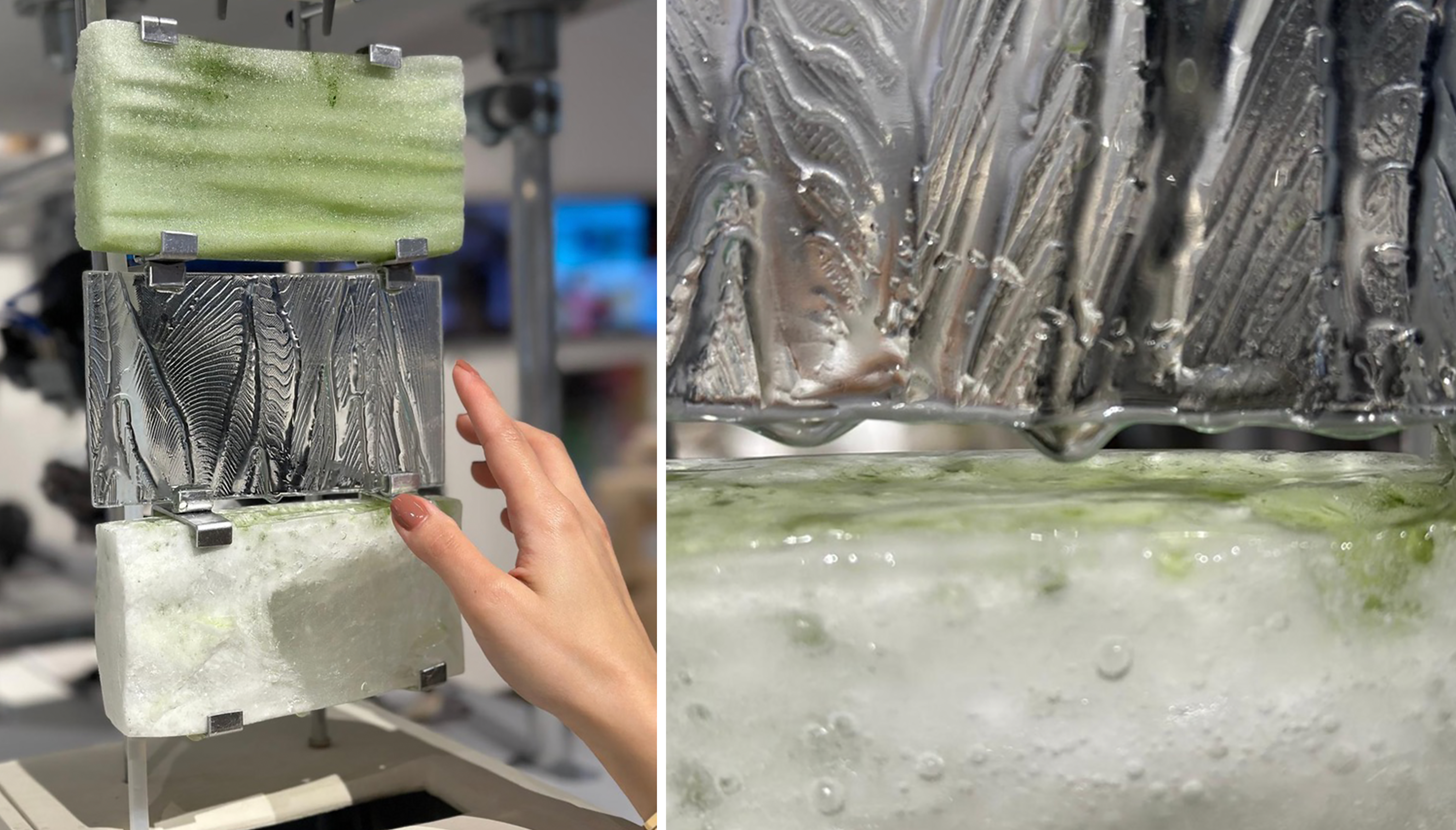
Glass as habitat system demonstrator showing sintered porous, foamed porous and slumped glass components, inoculated with C. vulgaris and documented at week 2 under uncontrolled indoor conditions.

Figure 3. Long description
The left photograph shows a prototype assembly held vertically with small metal clips. A green porous foamed glass piece is at the top, a clear textured slumped glass component is in the centre, and a white porous glass piece is at the bottom. A hand beside the assembly gives scale. The right photograph is a close-up showing the ridged, transparent slumped glass surface above a white-green porous glass component. The images show how sintered, foamed, and slumped glass parts combine into a semi-translucent scaffold after inoculation with C. vulgaris.
Methods for an ecosystem
The project was driven by an interdisciplinary methodology in which material, biological, environmental and computational logics co-evolve. The research map (Figure 2) shows environmental parameters, material properties, form/geometry, microclimates and embedded ecology as interdependent factors in a network of feedback loops. Bioreceptive performance emerged through interacting material parameters, porosity, permeability, surface roughness, pH and light transmittance, while measured material behaviours are linked to computational analyses of water flow and solar exposure to inform morphology and placement for growth-supportive conditions (Alfraih Reference Alfraih2025; Dhanesha Reference Dhanesha2025; Fang Reference Fang2025). Initial culturing of the non-sterile, indoor condition glass indicated the presence of a naturally established co-culture that developed from a Chlorella vulgaris system. Further research in partnership with microbiologists would give insight into how these microorganisms may be impacting the sustained algal presence over succession cycles within the pores. Observations and reculturing experiments of outdoor samples indicate that the microbial community was able to withstand winter conditions and re-establish with the introduction of diluted media solution.
In this sense, the method itself functions as an ecology, with knowledge and data produced at the interfaces. Craft constraints shape pore networks; biological requirements define microhabitats; computation models environmental responses and guides material mapping; and time reveals ecological succession, maintenance cycles and seasonal transformation (Alfraih Reference Alfraih2025; Dhanesha Reference Dhanesha2025; Fang Reference Fang2025).
Bioreceptive material library
The bioreceptive material library was informed by literature on porous and bioreceptive substrates, which identify interdependent properties governing biological colonisation (Cruz and Beckett Reference Cruz and Beckett2016; D’orazio et al. Reference D’orazio, Cursio, Graziani, Aquilanti, Osimani, Clementi, Yéprémian, Lariccia and Amoroso2014; Ferrandiz-Mas et al. Reference Ferrandiz-Mas, Bond, Zhang, Melchiorri and Cheeseman2016; Giassia Reference Giassia2022; Lubelli et al. Reference Lubelli, Moerman, Esposito and Mulder2021; Miller et al. Reference Miller, Sanmartn, Pereira-Pardo, Dionsio, Sáiz-Jiménez, Macedo and Prieto2012; Rotondi et al. Reference Rotondi, Gironi, Ciufo, Diana and Lucibello2024). Key parameters include surface texture/roughness, porosity, pore size distribution and connectivity, permeability, water absorption/retention, evaporation rate, pH/chemical composition and light transmission (Figure 2). In porous glass scaffolds, these variables act as a coupled system: surface microtexture supports attachment, while interconnected porosity provides habitat, surface area and transport pathways for water and nutrients (Giassia Reference Giassia2022; Lubelli et al. Reference Lubelli, Moerman, Esposito and Mulder2021; Miller et al. Reference Miller, Sanmartn, Pereira-Pardo, Dionsio, Sáiz-Jiménez, Macedo and Prieto2012; Mondo et al. Reference Mondo, Angelo, Carbone, Pollio and De Natale2018; Rotondi et al. Reference Rotondi, Gironi, Ciufo, Diana and Lucibello2024). Balancing micro- and macro-porosity sustains colonisation while maintaining structural integrity (D’orazio et al. Reference D’orazio, Cursio, Graziani, Aquilanti, Osimani, Clementi, Yéprémian, Lariccia and Amoroso2014; Ferrandiz-Mas et al. Reference Ferrandiz-Mas, Bond, Zhang, Melchiorri and Cheeseman2016). For photosynthetic organisms, optical behaviour is equally critical: light transmission and scattering shape growth depth, patterning and the potential for interiorised colonisation (Cruz and Beckett Reference Cruz and Beckett2016; Lubelli et al. Reference Lubelli, Moerman, Esposito and Mulder2021) (Figure 7).
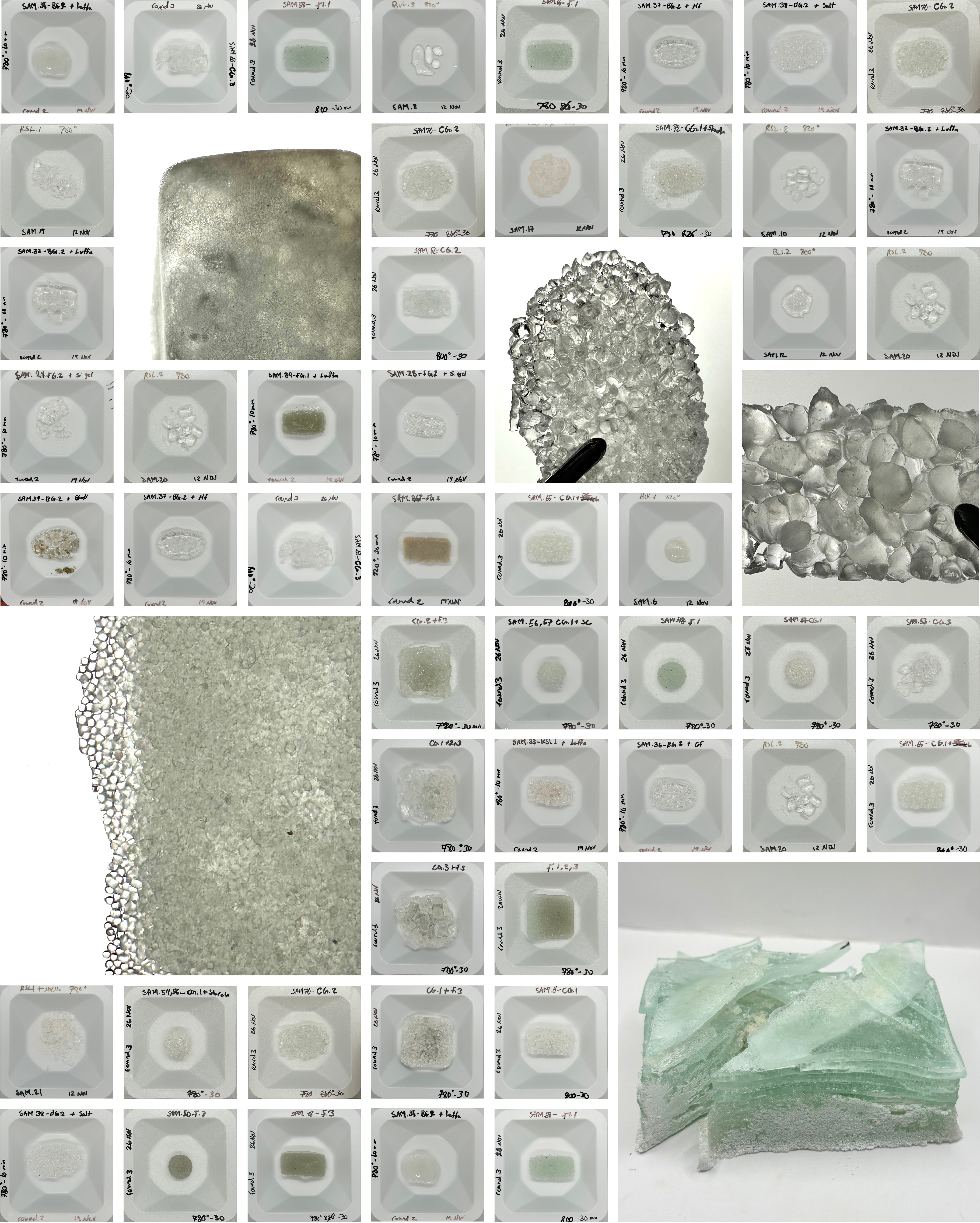
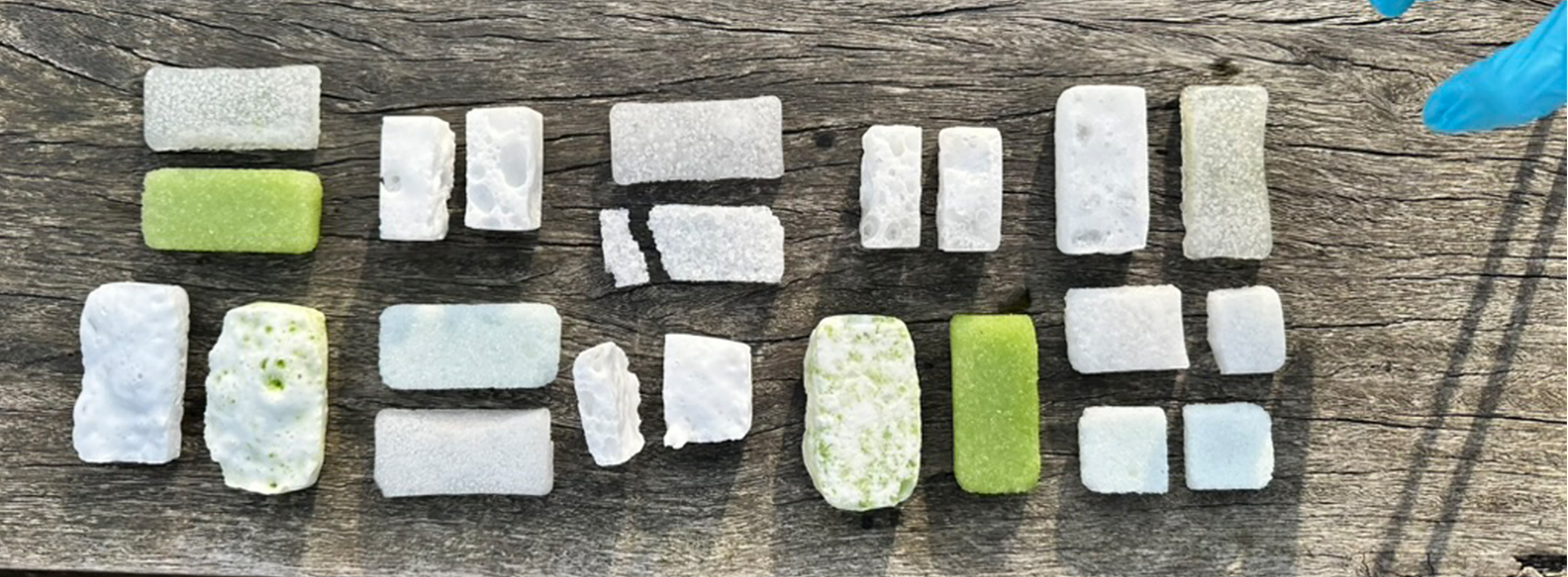
Series of initial exploratory material development samples, documenting variations in glass composition, particle size, firing schedule, foaming behaviour, surface texture, translucency and pore formation. These trials informed later material evaluation and biological inoculation.

Figure 4. Long description
The collage contains many small labelled experimental glass samples arranged around larger detail photographs. Most samples are pale green, white, or translucent and sit in small moulds or on white backgrounds. The larger images show foamed and sintered glass pieces with different pore sizes: some have fine, sponge-like porosity, while others contain larger bubbles or fused glass shards. The figure documents the breadth of early trials used to compare glass composition, particle size, firing schedule, surface texture, translucency, and pore formation before selecting samples for evaluation and biological inoculation.
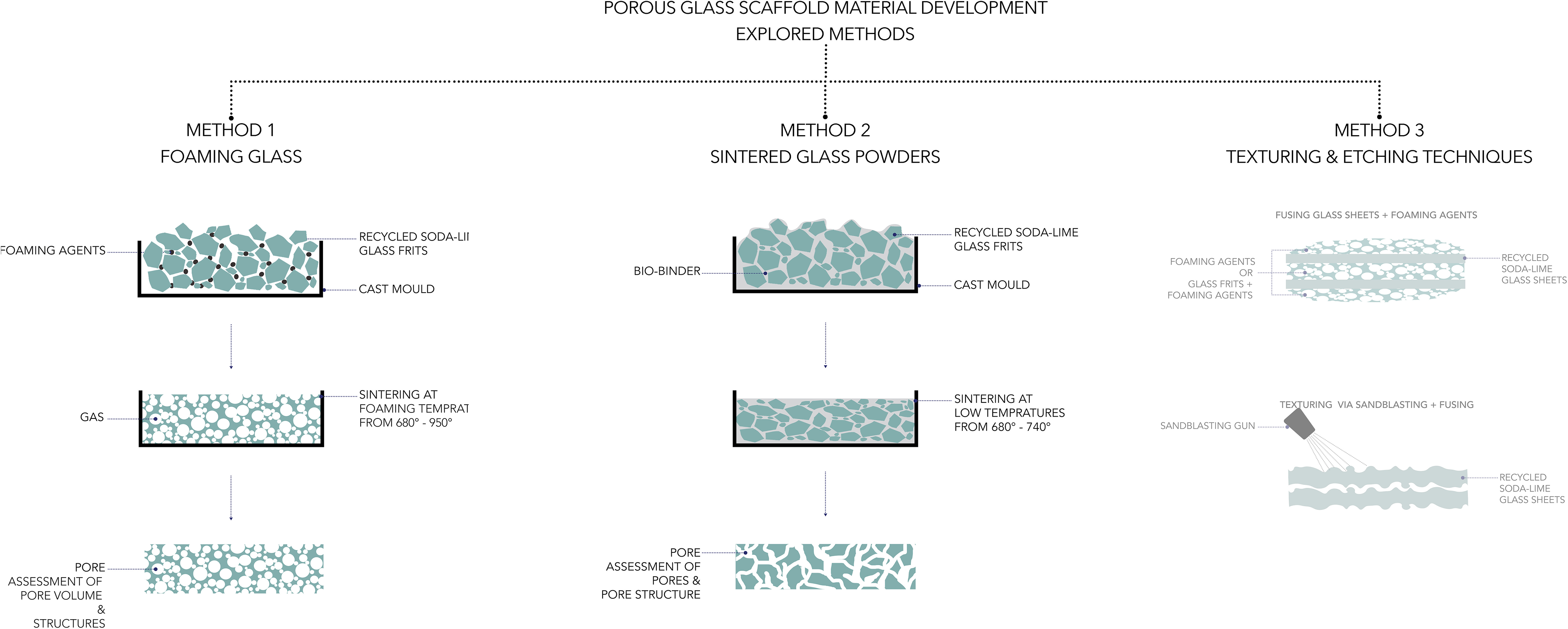
Proposal for material development methods. Methods 1 and 2 were taken forward into the material library.

Figure 5. Long description
The diagram is a process map for porous glass scaffold development. Method 1, foaming glass, combines foaming agents with recycled soda-lime glass frits in a cast mould; sintering at foaming temperatures produces gas expansion and a porous structure for assessment. Method 2, sintered glass powders, combines a bio-binder with recycled soda-lime glass frits in a cast mould; lower-temperature sintering partially fuses the particles and creates pores for assessment. Method 3, texturing and etching techniques, shows two routes: fusing glass sheets with foaming agents, and sandblasting or slumping to texture recycled glass sheets. The figure indicates that methods 1 and 2 were carried forward into the material library.
Material library samples, with selected specimens inoculated with C. vulgaris algae.

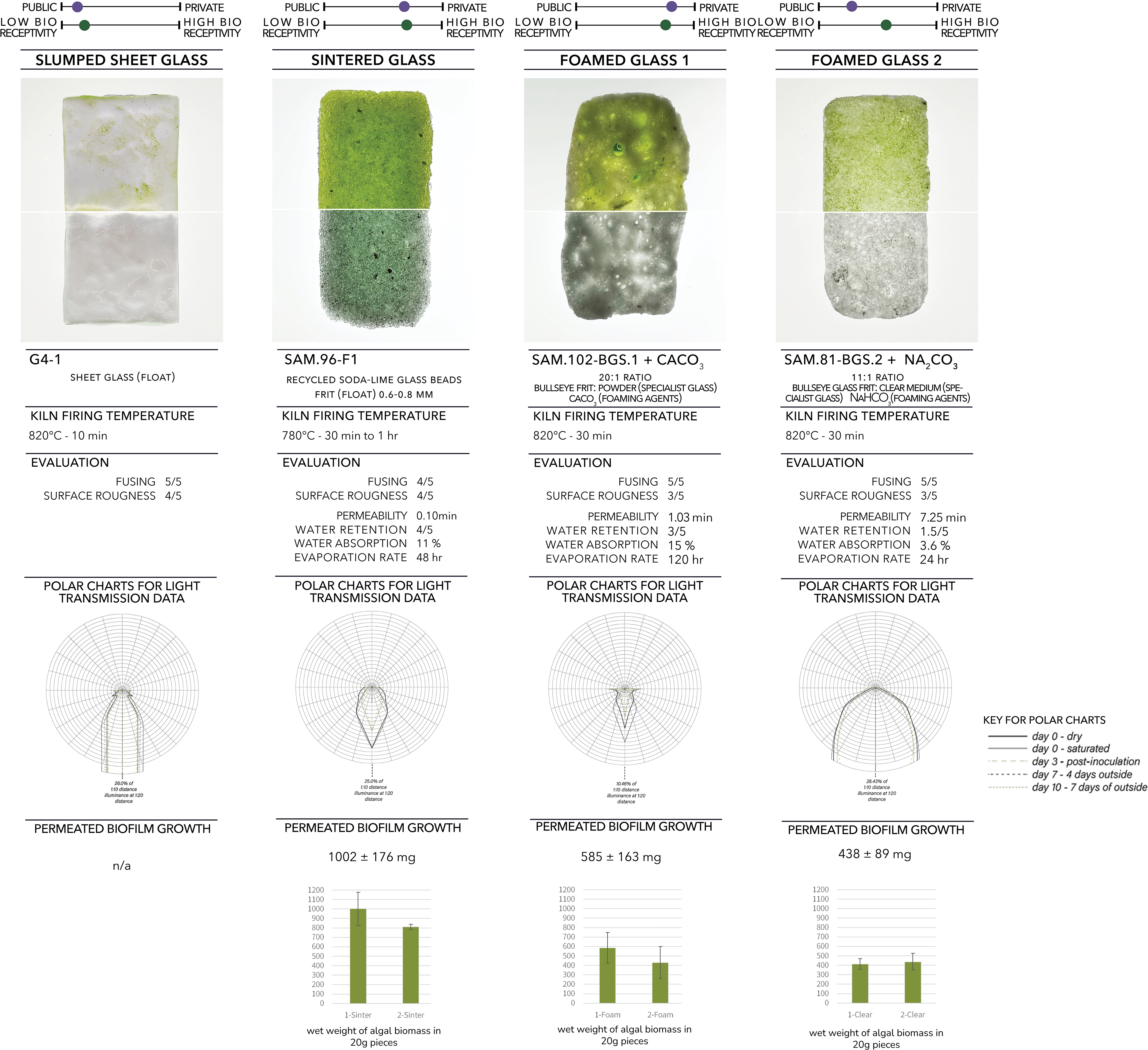
Material library and physical experimental data: Evaluation of bioreceptivity gradients from low to high and their spatial application from private-to-public zones. Images showing glass pieces with C.vulgaris growth vs. day 0 of inoculation; Properties measured include permeability (time to penetrate horizontally), water retention (vertical capillary action, 0–5 rating), absorption (weight change after 24 hrs submersion), evaporation (drying time), light transmission and scattering (measured using illuminance spectrophotometer and represented through polar charts); 2-week permeated biofilm growth measured (indoor conditions, media flow rate of 0.56
 $\pm$
0.12 mL/s and 1.67
 $\pm$
0.01 mL/s respectively for each glass type, wet biomass weight recorded).

Figure 7. Long description
The figure compares four material types: slumped sheet glass G4-1, sintered glass SAM.96-F1, foamed glass 1 SAM.102-BGS.1 with calcium carbonate, and foamed glass 2 SAM.81-BGS.2 with sodium carbonate. Each column shows a public-to-private and low-to-high bioreceptivity gradient, a photograph comparing algal growth with day 0, firing temperature, material evaluations, light transmission polar charts, and permeated biofilm growth. The slumped glass is fused at 820 degrees C for 10 minutes and has no recorded permeated biofilm growth. The sintered glass is fired at 780 degrees C for 30 minutes to 1 hour, with 4/5 fusing, 4/5 surface roughness, 0.10 minute permeability, 4/5 water retention, 11% water absorption, 48 hour evaporation, and 1002 plus or minus 176 mg biofilm growth. Foamed glass 1 is fired at 820 degrees C for 30 minutes, with 5/5 fusing, 3/5 surface roughness, 1.03 minute permeability, 3/5 water retention, 15% water absorption, 120 hour evaporation, and 585 plus or minus 163 mg biofilm growth. Foamed glass 2 is fired at 820 degrees C for 30 minutes, with 5/5 fusing, 3/5 surface roughness, 7.25 minute permeability, 1.5/5 water retention, 3.6% water absorption, 24 hour evaporation, and 438 plus or minus 89 mg biofilm growth. The polar charts compare light transmission and scattering across dry, saturated, post-inoculation, and outdoor exposure conditions.
To translate these parameters into a controllable design and fabrication framework, three porous-glass routes were explored: foamed glass, sintered glass and textured/etched glass (Figure 5). The foamed route mixed foaming agents into glass frit before firing to induce gas expansion, generating an interconnected porous network (Bernardo et al. Reference Bernardo, Scarinci, Bertuzzi, Ercole and Ramon2010; Fernandes et al. Reference Fernandes, Tulyaganov and Ferreira2009; Fedorov and Pilon Reference Fedorov and Pilon2002; Giassia Reference Giassia2022; Inayat et al. Reference Inayat, Reinhardt, Uhlig, Einicke and Enke2013; Mohammed et al. Reference Mohammed, Simon and Géber2022). Porosity and pore size distribution are tuned through frit particle size, foaming-agent type and concentration and heating profile, producing scaffold conditions that support photosynthetic cultures through increased surface area and fluid pathways (Bernardo et al. Reference Bernardo, Scarinci, Bertuzzi, Ercole and Ramon2010; Inayat et al. Reference Inayat, Reinhardt, Uhlig, Einicke and Enke2013; Mohammed et al. Reference Mohammed, Simon and Géber2022). The sintered route forms porosity through partial fusion of compacted glass particles under controlled heating without fully melting or using chemical foaming agents; particle-size distribution, packing density, sintering temperature and dwell time shape pore morphology and scaffold performance (Ferrandiz-Mas et al. Reference Ferrandiz-Mas, Bond, Zhang, Melchiorri and Cheeseman2016). Together, these approaches offer complementary routes for engineering pore structure, connectivity and material behaviour in relation to bioreceptive performance (Figures 4 and 6).
From these studies, a material library was developed to tune bioreceptivity by varying surface texture, composition, grain size, firing schedule and fabrication route across a comparative sample set (Figure 7). Porosity and pore size distribution were treated as design variables and engineered through optimisation of firing temperature and frit particle-size distribution (Bernardo et al. Reference Bernardo, Scarinci, Bertuzzi, Ercole and Ramon2010; Ferrandiz-Mas et al. Reference Ferrandiz-Mas, Bond, Zhang, Melchiorri and Cheeseman2016). Tests for absorption, water retention, evaporation, permeability, light transmission/scattering and bioreceptivity indicators formed a comparative knowledge base for design decisions. The library evaluates bioreceptivity gradients (low–high) and translates them into spatial application across private-to-public zones, enabling material selection and mapping strategies in which growth would be encouraged, moderated or constrained according to intended use (Figure 7).
Porous glass as a living interface: Experimental processes
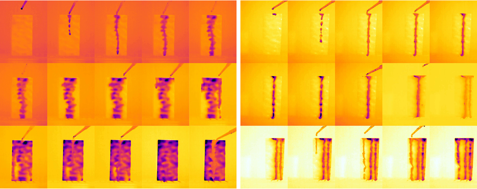
To assess the physical qualities of materials, a series of tests examined four primary characteristics: porosity (Figure 9), interactions with water (Figures 7 and 10), optical performance (Figures 7, 12 and 13) and the capacity to support growth of photosynthetic organisms (Figures 8, 11, 14, 15 and 17–19).
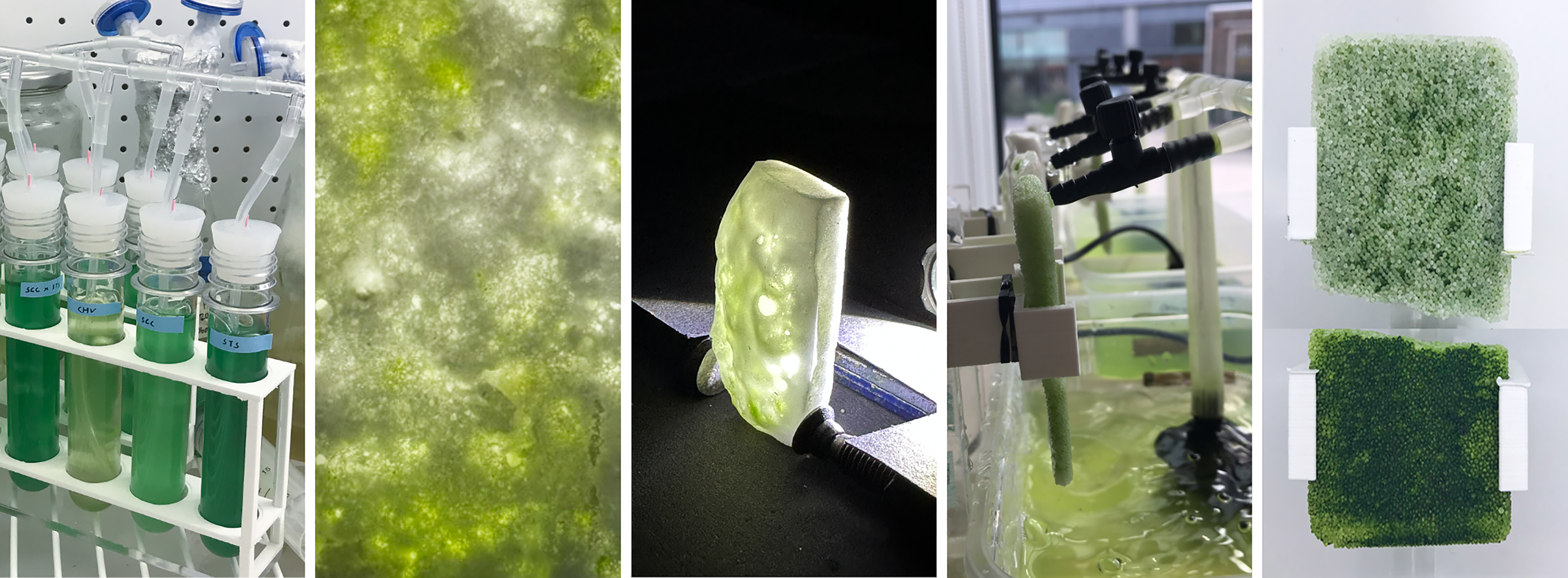
Bio-integration experiments: co-culturing, longevity, light-quality assessment, drip systems and harvesting methods.

Figure 8. Long description
The image sequence shows different stages and tests for integrating C. vulgaris with porous glass. From left to right, the panels show test tubes containing green algal cultures, a close-up of green growth within a translucent porous glass texture, a glass sample illuminated by a light source to assess light quality, an indoor drip system with tubing positioned near a window, and two glass samples in a vertical holder showing different densities of green biofilm growth. Together, the panels summarise co-culturing, longevity, light-quality assessment, irrigation, and harvesting methods.
Cross-sectional cuts of porous glass samples used to assess pore distribution, pore size and network connectivity. Scale bars indicating 5 mm.

Figure 9. Long description
Five horizontal cross-sections are shown with 5 mm scale bars. The sintered sample has a fine, relatively uniform granular pore structure. The foamed samples show larger and more irregular pores, ranging from small rounded cells to large bubble-like voids. One cross-section is stained blue, making the pore network more visible. The comparison shows how different fabrication methods and recipes produce different internal habitats for water movement and biological growth.
Thermal camera video screenshots documenting water dripping across the surface and interacting with the pore network of the sintered glass sample (left) and the foamed glass (right).

Figure 10. Long description
The figure contains thermal video frames arranged as two groups. The left group shows a sintered glass sample, and the right group shows a foamed glass sample. Warm areas appear yellow to orange, while cooler wet paths appear purple. The images trace how drops travel down each surface and interact with the pore network. The comparison indicates differences in water distribution and retention between the sintered and foamed glass samples.
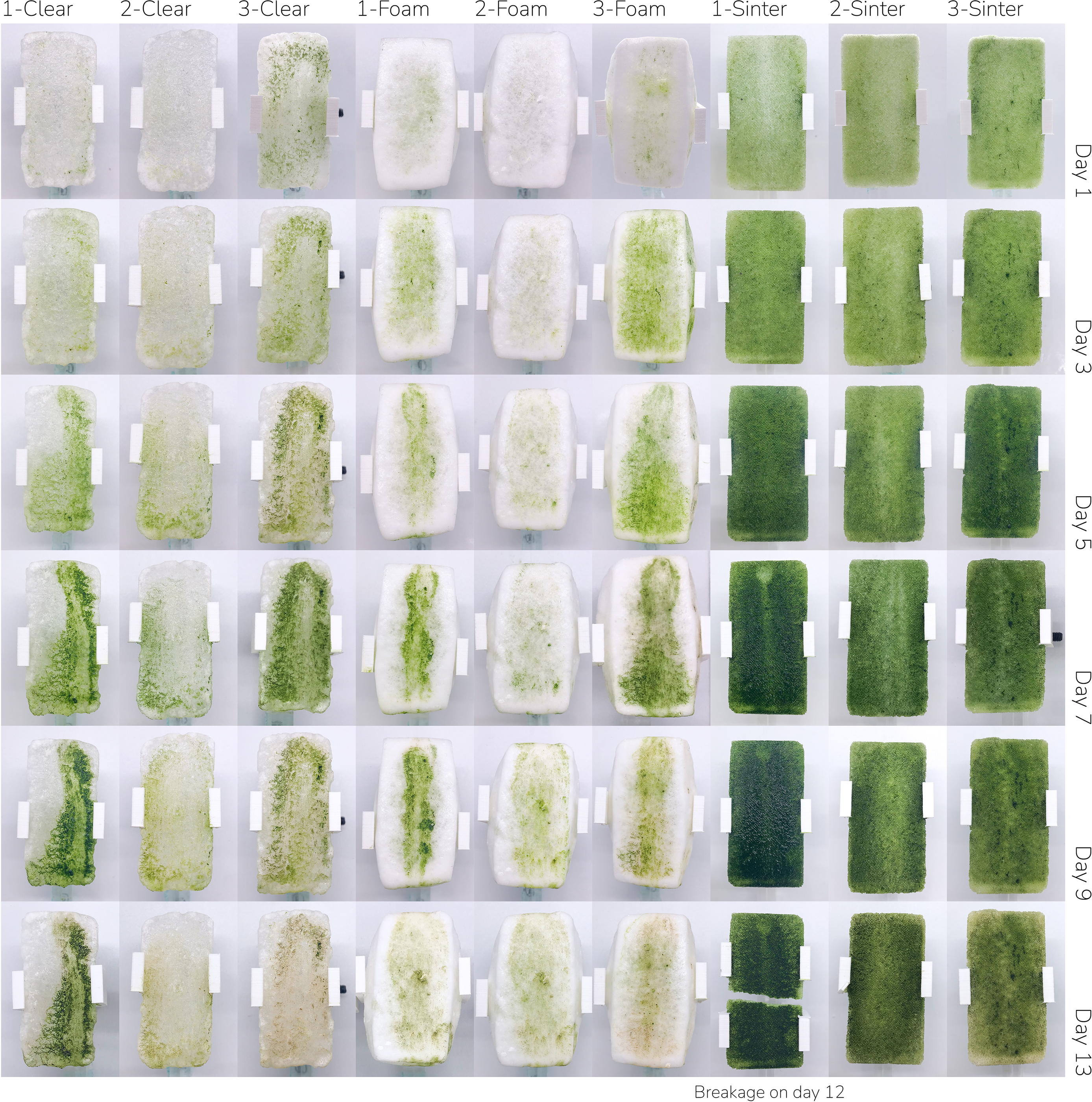
Visual timeline of porous glass samples in the irrigation system experiment, inoculated with C. vulgaris under uncontrolled indoor conditions, documenting 2-week permeated biofilm growth. Flow rates measured 0.56
 $\pm$
0.12 mL/s for Group 1 (1-Clear, 1-Foam, 1-Sinter) and Group 3 (3-Clear, 3-Foam, 3-Sinter); and 1.67
 $\pm$
0.01 mL/s for Group 2 (2-Clear, 2-Foam and 2-Sinter). Samples in Group 3 were additionally preconditioned with Pseudomonas putida. Methodology adapted from (Schnurr et al. Reference Schnurr, Espie and Allen2013; Sekar et al. Reference Sekar, Venugopalan, Satpathy, Nair and Rao2004).

Figure 11. Long description
The grid tracks nine samples labelled 1-Clear, 2-Clear, 3-Clear, 1-Foam, 2-Foam, 3-Foam, 1-Sinter, 2-Sinter, and 3-Sinter across days 1, 3, 5, 7, 9, and 13. The clear samples show limited and streaked green growth, the foamed samples develop patchy green biofilm, and the sintered samples become the darkest and most uniformly green. A note marks breakage on day 12 for one sample. The caption states that the samples were inoculated with C. vulgaris under uncontrolled indoor conditions, with two flow-rate groups and one group additionally preconditioned with Pseudomonas putida.
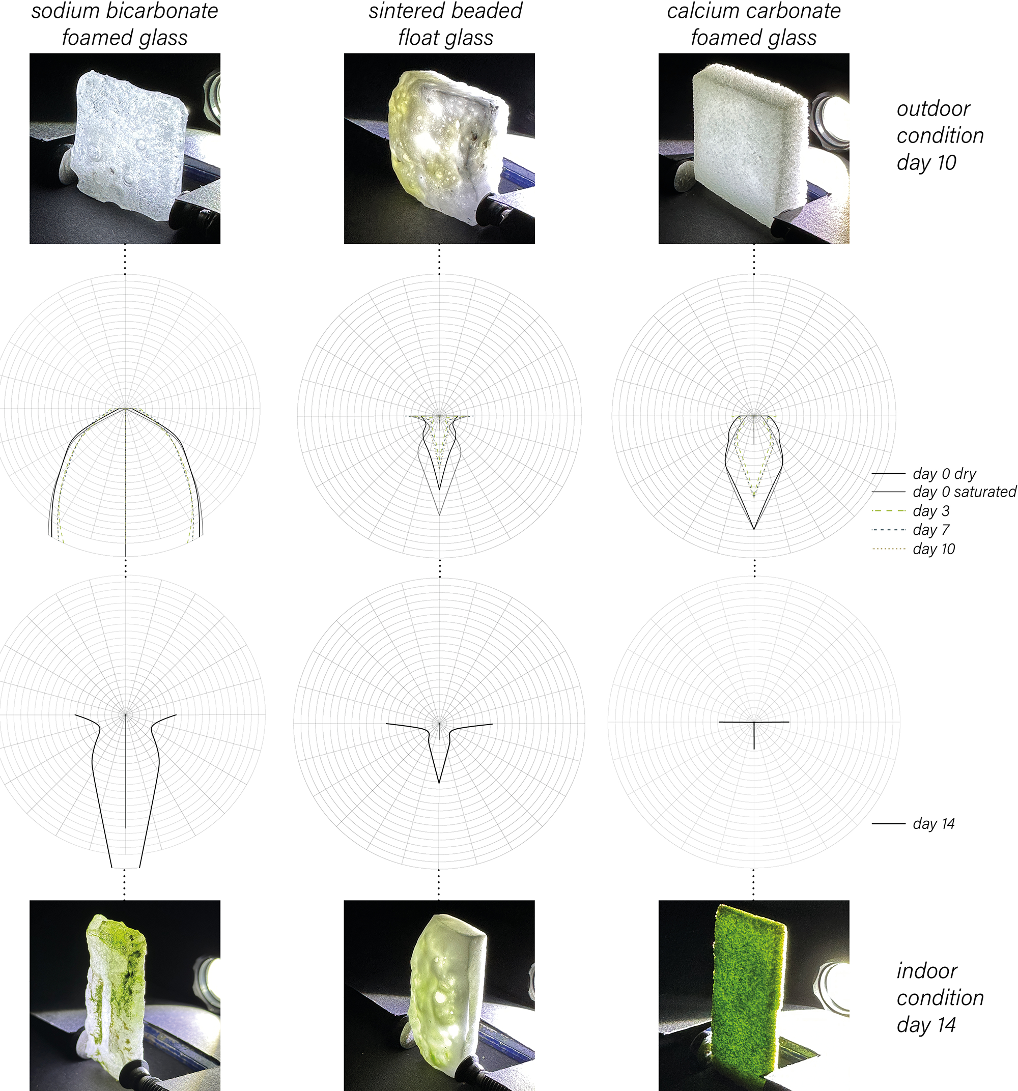
Light transmission and scattering of the glass samples were measured using an illuminance spectrophotometer and represented as polar charts.

Figure 12. Long description
The figure compares sodium bicarbonate foamed glass, sintered beaded float glass, and calcium carbonate foamed glass under outdoor day 10 and indoor day 14 conditions. Photographs show each sample held in front of a light source, and polar charts below each photograph plot measured light transmission and scattering over time. The charts show that each glass type diffuses light differently as it becomes saturated, inoculated, or exposed outdoors, supporting decisions about translucency, growth depth, and interior light quality.
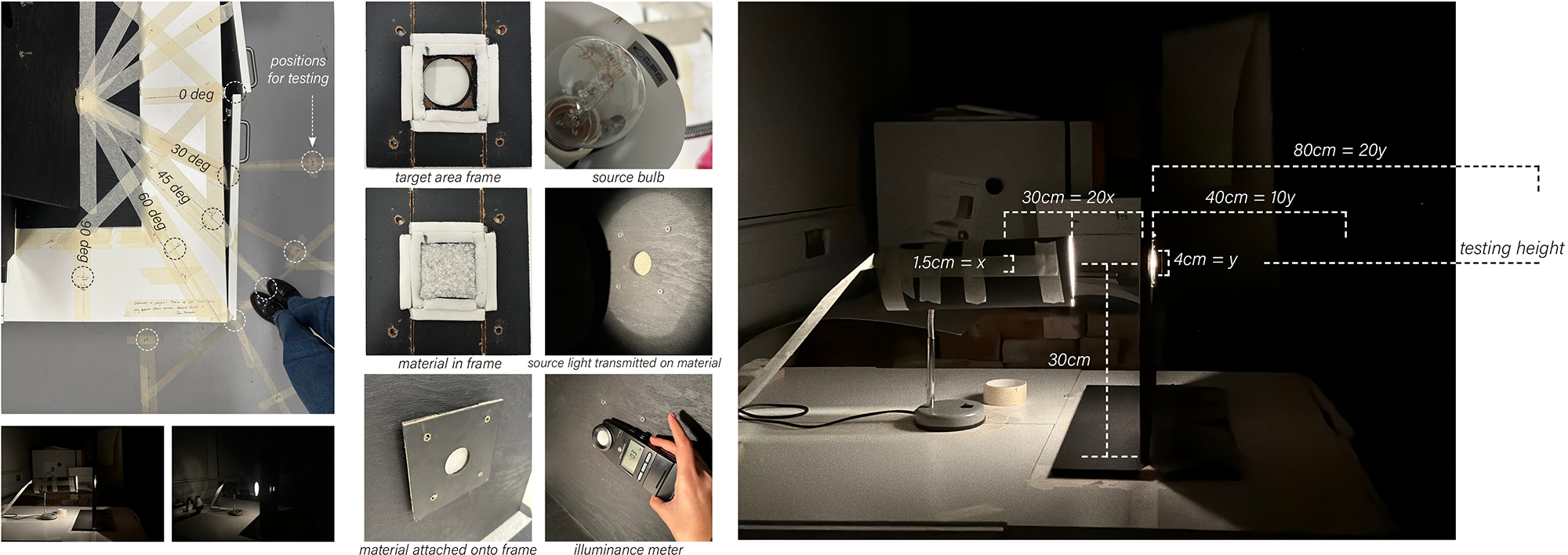
Experimental set-up for light transmission and scattering measurements.

Figure 13. Long description
The figure shows the experimental setup used for light measurements. Small photographs document a sample holder, a light source, measuring equipment, and a darkened testing arrangement. A larger diagram indicates the relative positions and distances of the light source, glass sample, and measurement point, with dimensions such as 150 mm, 300 mm, and 450 mm. The setup establishes a controlled path for comparing how different porous glass samples transmit and scatter light.
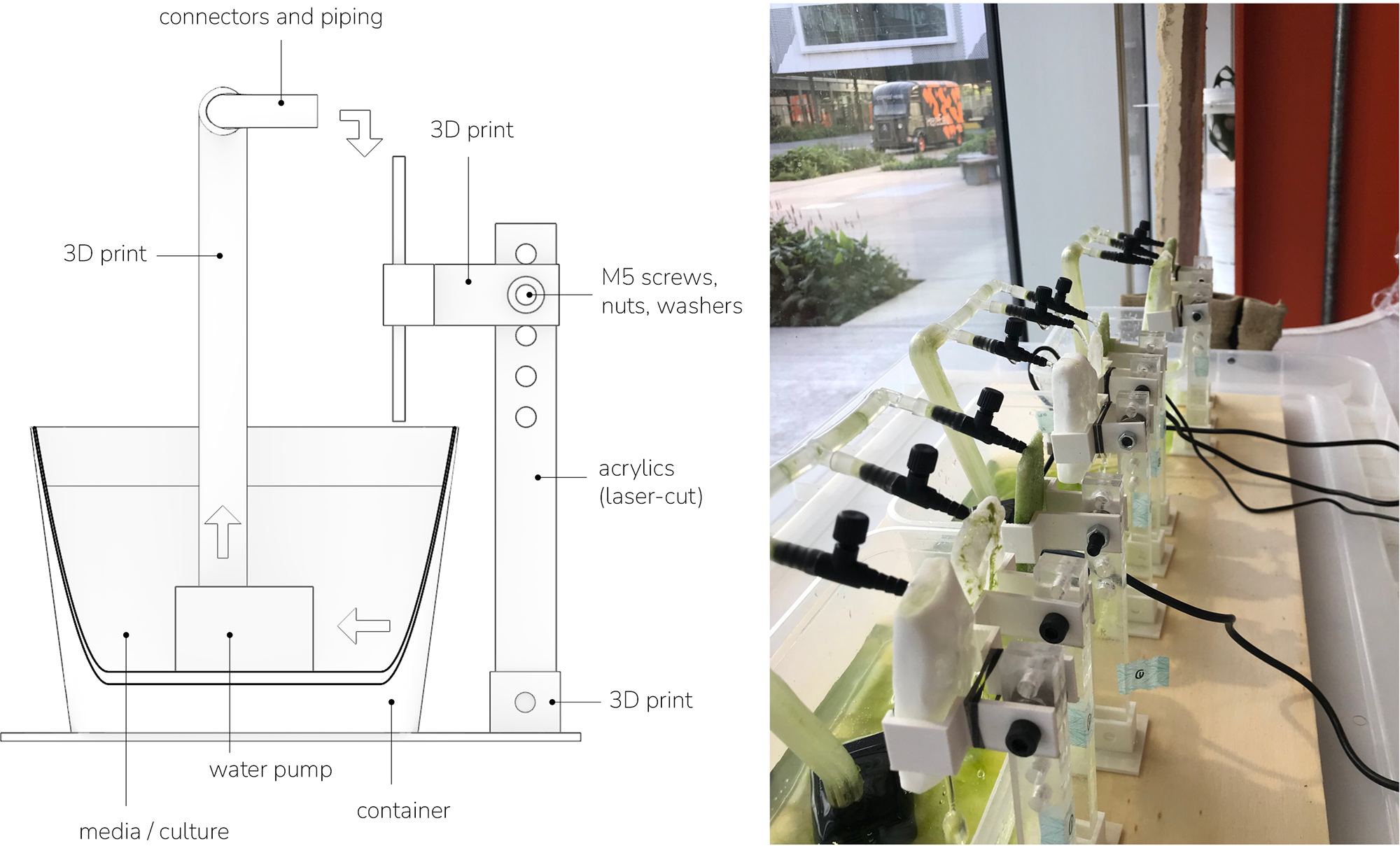
Experimental set-up for the irrigation system experiment.

Figure 14. Long description
The left side is a schematic drawing of the irrigation apparatus, including a water pump, container, tubing, connectors, 3D printed frame components, and a sample holder with screws and washers. The right side is a photograph of the assembled system by a window, where several glass samples are clamped in place and connected to tubing. The system was used to deliver media or culture over the samples and simulate a facade irrigation strategy.
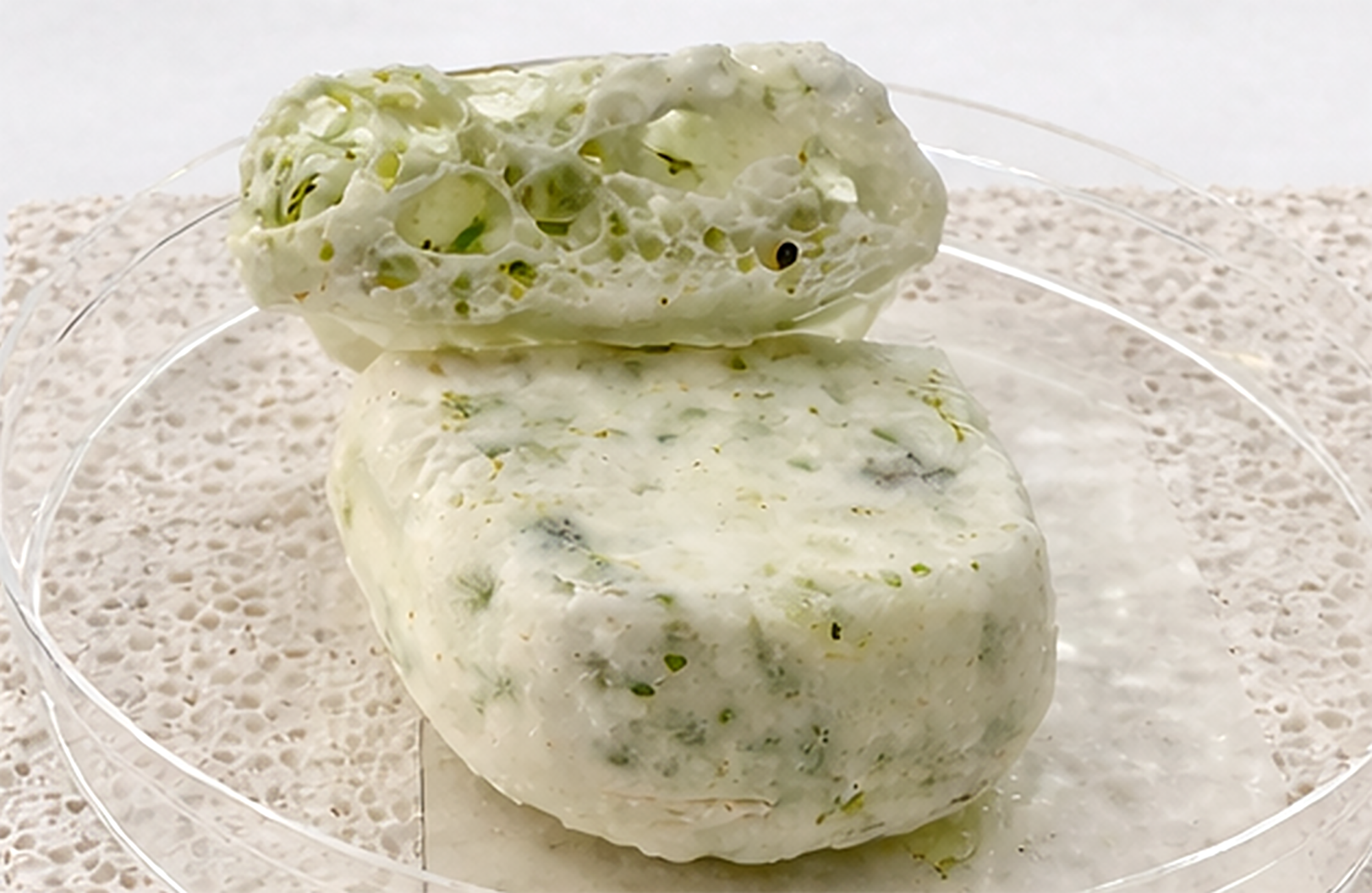
Prototype 1 porous glass morphology (1:1 scale), front view, showing a clear-to-foamed gradient, inoculated with C. vulgaris and observed at week 9 under uncontrolled indoor conditions.

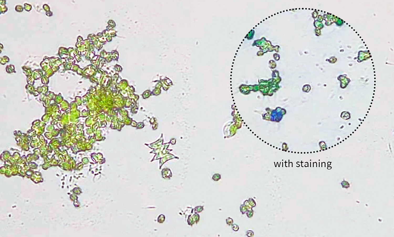
Microscopy (40x) following preliminary sonication of glass samples for methylene blue staining trials unexpectedly identified cells from genus Scenedesmaceae, pointing to an area of interest for further studies.

Figure 16. Long description
The main microscope image shows clusters of green photosynthetic cells and small particles on a pale background. A dashed circular inset highlights cells after staining, including blue-green fragments. The caption identifies the image as 40x microscopy following sonication and methylene blue staining trials, and notes that cells from the genus Scenedesmaceae were unexpectedly identified, pointing to an area for further study.
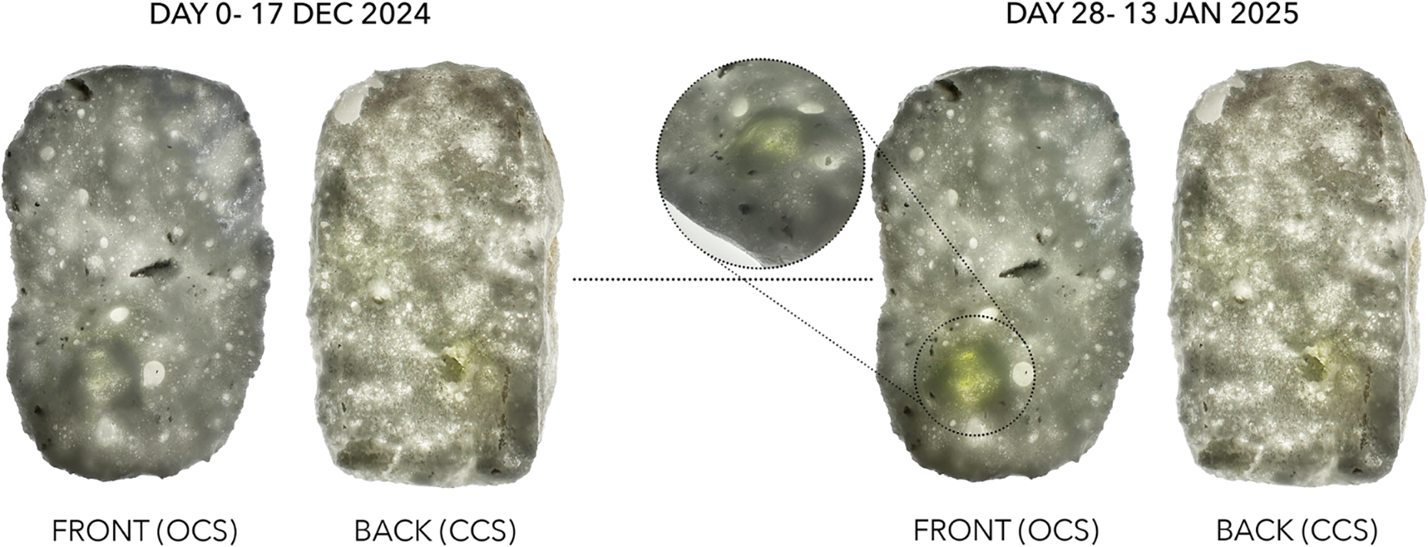
Bioreceptivity experiment for foamed glass sample SAM.102-BGS.1, documenting a winter-season growth timeline and the first evidence of life within the pore network, inoculated with C. vulgaris (uncontrolled indoor incubation).

Figure 17. Long description
The figure compares front and back views of the foamed glass sample at day 0 and day 28 during winter indoor incubation. The day 0 images show a mostly grey-white porous sample. By day 28, small green areas appear in the front view and within a magnified circular callout, indicating the first visible evidence of biological growth inside the pores. The back view remains lighter, showing uneven colonisation through the material.
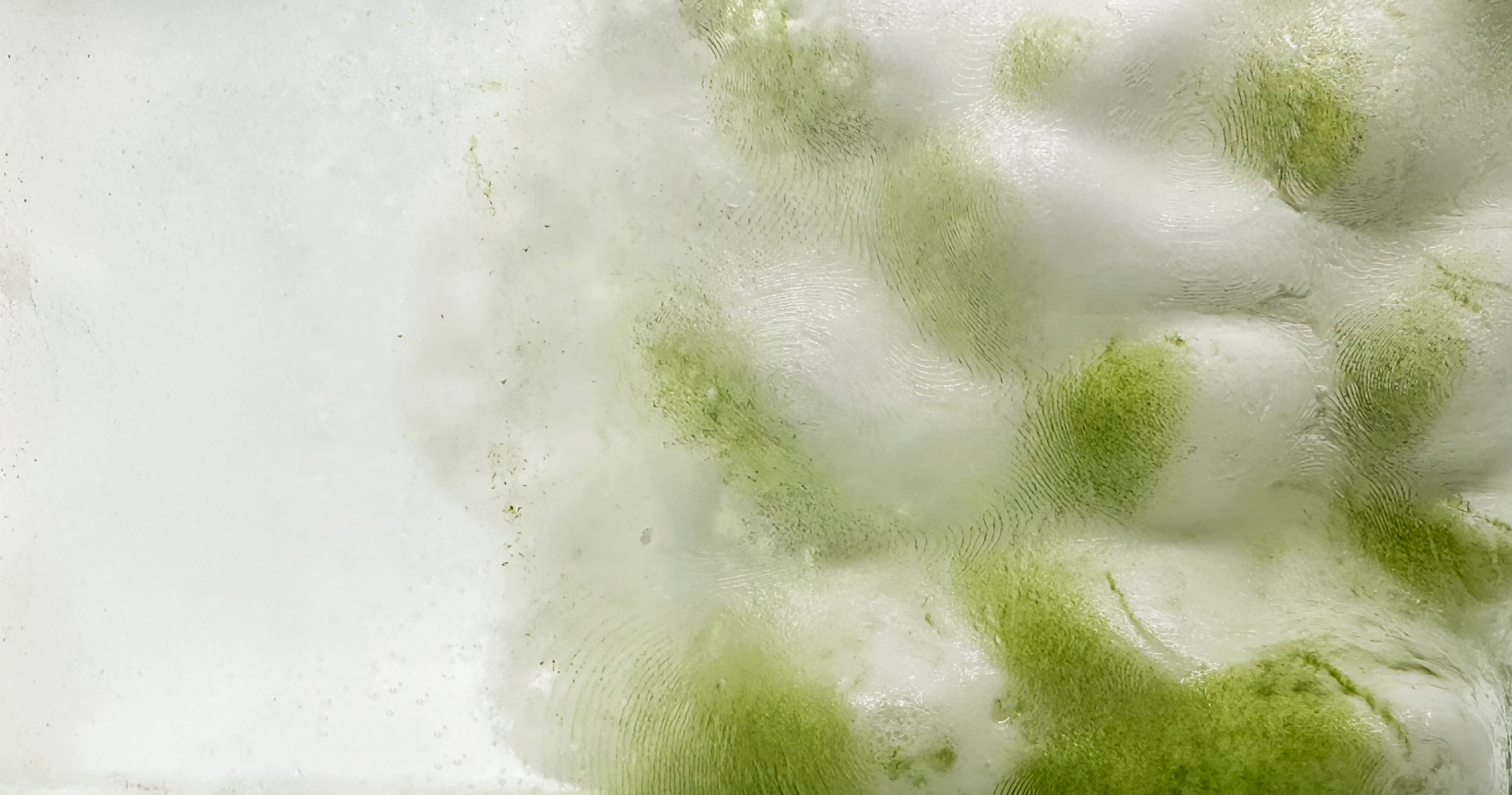
Section cut of a foamed glass sample showing biological growth within the pore network.

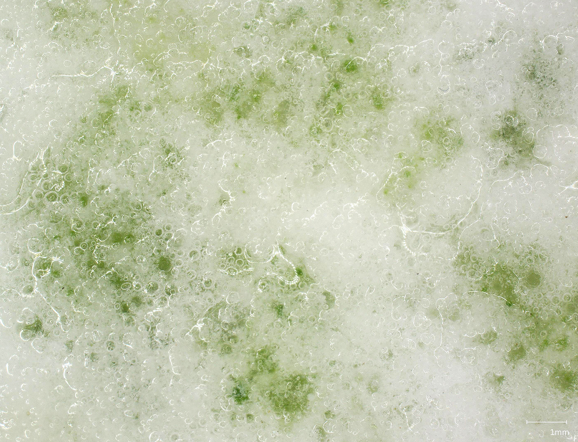
Digital micrograph (20
 $\! \times\!$
) of foamed glass sample (SAM.102-BGS.1), inoculated with C. vulgaris, week 10, cast-side surface (uncontrolled indoor incubation).

All experiments were conducted under non-sterile conditions, with samples either placed indoors, right next to windows for access to natural light (Figure 14) or outdoors with partial sheltering. Water-related studies observed permeability, water retention, absorption, evaporation while light tests evaluated transmission and diffusion, both with and without algal growth. All bioreceptive studies in this project use Chlorella vulgaris (C.vulgaris) as a model organism, they are unicellular, photosynthetic organisms that play a crucial role in the global carbon cycle with long histories of use across cultures and industries. Glass samples were inoculated using two different methods, both occurring after the glass’ firing process. The first is a submerging method, adapted from Ferrándiz-Mas et al. (Reference Ferrandiz-Mas, Bond, Zhang, Melchiorri and Cheeseman2016), in which glass samples were first submerged in di-water for 48hrs to neutralise, then in an algal culture in Cell-Hi HP media (Figures 1, 6, 15,17–19, 23 and 24). The second method was adapted from permeated biofilm growth systems by Sekar et al. (Reference Sekar, Venugopalan, Satpathy, Nair and Rao2004) and Schnurr et al. (Reference Schnurr, Espie and Allen2013), simulating the proposed façade irrigation strategy where inoculation occurs after the assembly of glass components in situ (Figures 3, 11 and 12).
Not only do these properties help determine whether the glass can successfully host desired organisms, they also provide guidelines informing design decisions for the speculative façade (Figure 20). Light transmission studies offered initial insights into the kinds of interior environments anticipated (Figures 7 and 12), suggesting a gradient of translucency and presence of natural lighting. Together, they also help to determine the maximum thickness of materials before it becomes undesirable for biological growth within the panel and in the space beyond. Preliminary sonication and methylene blue staining processes adapted from (Gao et al. Reference Gao, Yang, Li, Zeng, Ma and Li2015; Huang et al. Reference Huang, Cornejo, Bush and Jones1986; Imase et al. Reference Imase, Ohko, Mio and Hanada2013) were trialled as a method for estimating wet biomass weights and assessing cell viability (Figures 7 and 16). These techniques offer potential pathways for understanding how the system reacts to different environmental conditions beyond visual observations.
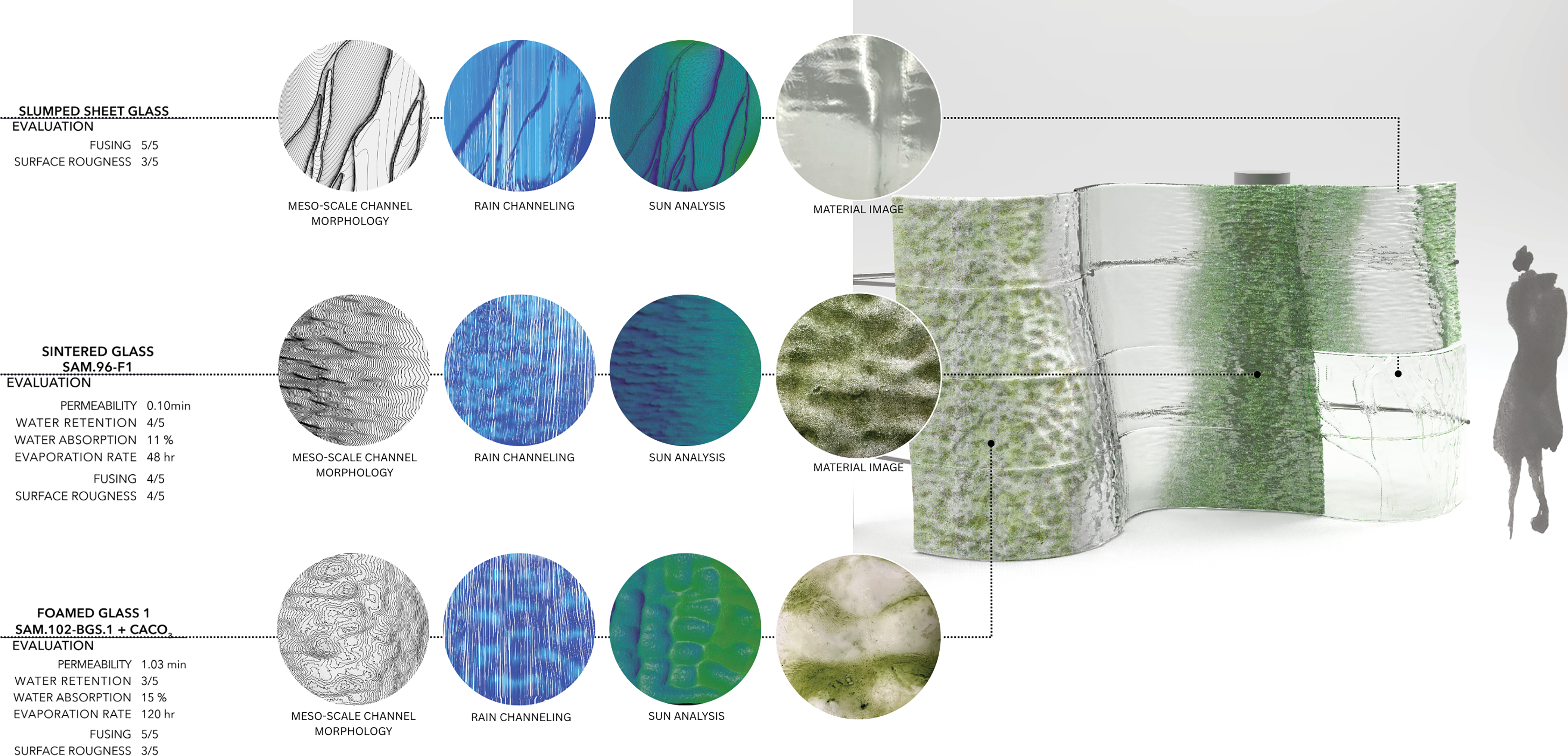
A twelve-unit bioreceptive porous glass façade render showing ecological growth, with texture images of sintered, foamed and slumped glass prototypes, material characterisation, and studies of form development, sun/rain performance, morphology and fabrication evaluation.

Figure 20. Long description
The figure combines material characterisation with an architectural facade proposal. On the left, three material rows describe slumped sheet glass, sintered glass SAM.96-F1, and foamed glass 1 SAM.102-BGS.1 with calcium carbonate. Each row includes evaluation values, circular thumbnails of meso-scale channel morphology, rain channelling, sun analysis, and a material image. Dotted leader lines connect these studies to a curved twelve-unit facade render on the right. The facade alternates clear, translucent, and green bioreceptive glass areas, with a human silhouette for scale. The image shows how material properties, environmental analysis, morphology, and fabrication evaluation inform the placement of different glass types across the facade.
In natural systems, microorganisms form complex symbiotic relationships, whether mutualistic or parasitic. Similar dynamics were observed under the non-sterile experimental conditions, where co-cultures emerged alongside C. vulgaris. Microscopy revealed additional photosynthetic organisms (Figure 16), and sampling on LB agar also confirmed broader microbial presence. These observations open exploratory directions, including collaboration with microbiologists to develop co-cultures with nitrogen-fixing species, to potentially reduce reliance on specialised media and understand long-term lifecycles.
Beyond surface greening: Deep bioreceptivity
Learning from precedents in bioreceptive material, this work recognises that photosynthetic life often occupies the exteriors of these materials. The substrate, in the precedents, play a critical role in maintaining the right environmental conditions to host life on their surfaces.
Aided by the semi-translucent glass and its interconnected pore networks, the material here (Figures 17–19) is no longer limited to surface greening. The deep pore structure provides space for internal habitats protected against extreme weather conditions and human intervention. This enables photosynthetic microbial communities to inhabit protected microclimates within the glass, supporting persistent growth within the scaffold. The approach draws parallels with endolithic microbial systems, organisms that live within rock matrices, and with life found beneath ice in the Arctic, where they enable survival in otherwise harsh environments.
Fabrication and computation for biodesign enhancement
Glass, in its purest form, is unforgiving. Every blemish revealed, every irregularity demanding maintenance in service for the obsession with perfection and clarity. Porous glass offers a vastly different set of characteristics from traditional glass. The gradient of opacities opens possibility for variations in privacy, and added porosity could help to mitigate urban issues such as flash flooding and urban greening, making it a valuable material for architectural façade applications.
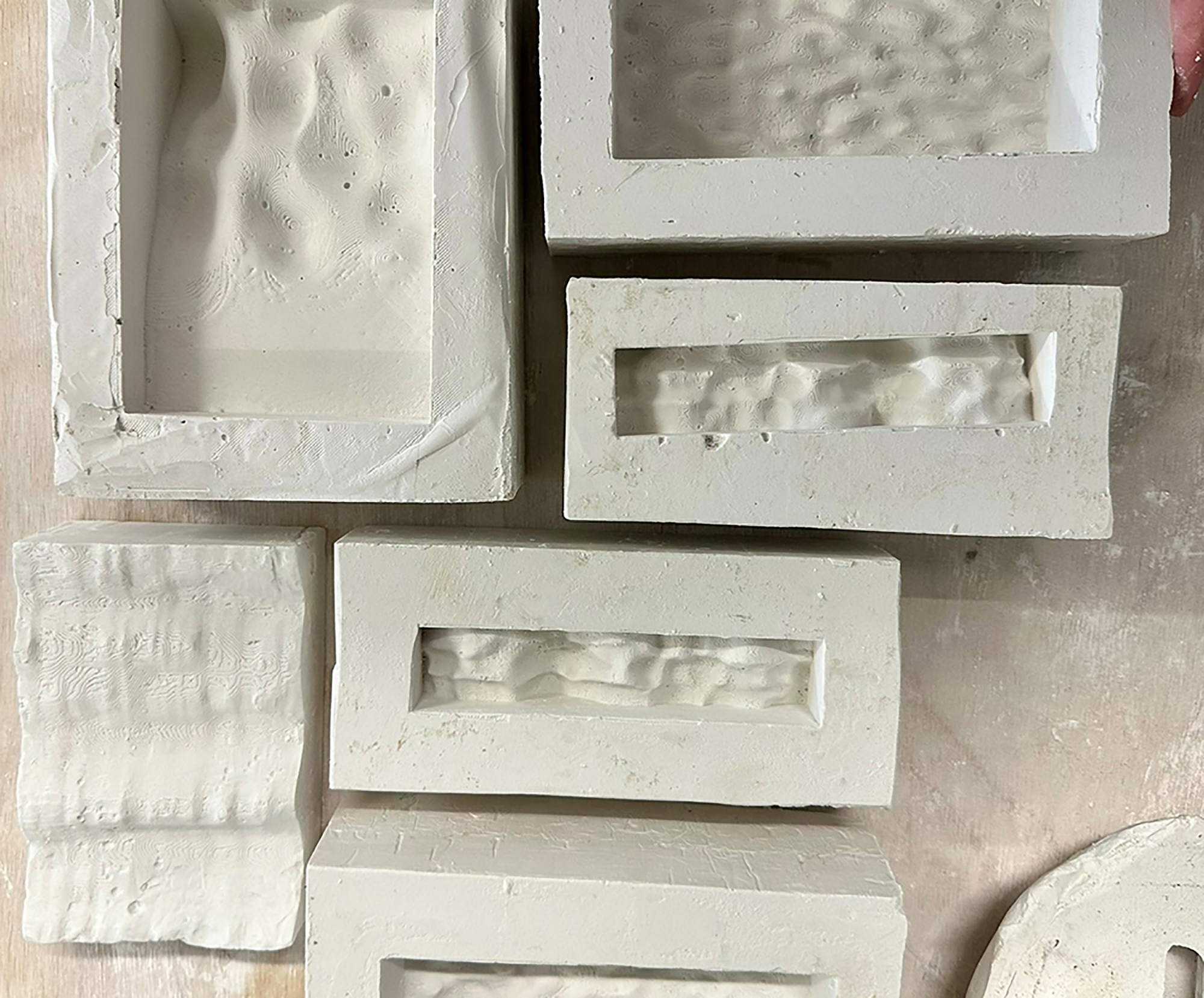
Three of the most promising glass types; sintered frit beads, slumped sheet and foamed powder glass (Figure 3) were strategically distributed across a multistorey building façade situated in London, demonstrating how the various types of glass can work together to create an environment that supports algal growth and user interaction. Each type of glass was fabricated and designed based on acquired data (Figures 7 and 9–12) and environmental data with surface patterning to support water movement and microbial growth over time. Demonstrator panels were cast through techniques used by glass sculptors and modified to integrate data-driven digital geometries. 3D printed moulds were used to cast wax, which were then used to fabricate two-part refractory casts for the glass to be fired within, creating panels of glass shaped on both sides. The slumped glass sheets were cast on open-face moulds without the wax cast step (Figure 21). These panels were kiln fired between 750–820°C, about half the temperature of traditional glass firings for flat sheets of glass, consuming less energy in the process.
A collection of open-face and slumping refractory casts, produced as part of the prototype fabrication process.

Each panel was designed to be between 3 mm–5 cm thick for installation compatibility with traditional glazing systems. This also allows the glass to be used for retrofits or new construction without extra skill training. Each type of glass was placed on the façade to best support their inherent properties (Figure 20). Sintered glass was positioned in gutter-like zones, acting as a distributor that channels rainwater, nutrients and microorganisms to adjacent materials (Figures 7 and 10). Foamed pieces are better suited in areas of higher sun exposure, where moisture and growth can penetrate deeper into the pore networks (Figures 7, 9 and 18). The surface morphology of each panel was primarily designed for water retention and movement (Figure 20); the foamed glass surface was dappled with shallow pools to extend time for water to seep through, the sintered patterned with horizontal shelf-like ribbing to slow down water flow and lastly the slumped with branching patterns to guide cultures and water flow between neighbouring panels. The panels transitions from porous to clear to control opacity and growth patterning across the building.
Organism and time as co-designers
Material, microculture and morphology come together to create a design that is expected to change over time, such that a user would never come across the same space twice. With glass testing taking place over 5 months, in non-sterile indoor and outdoor conditions, the speculated weathering and evolution of the design from the algae lifecycle to the overall environmental weathering were observed through the peaks of London’s season variation, providing a guideline for how the design may change between hours and days and seasons (Figures 22–24).
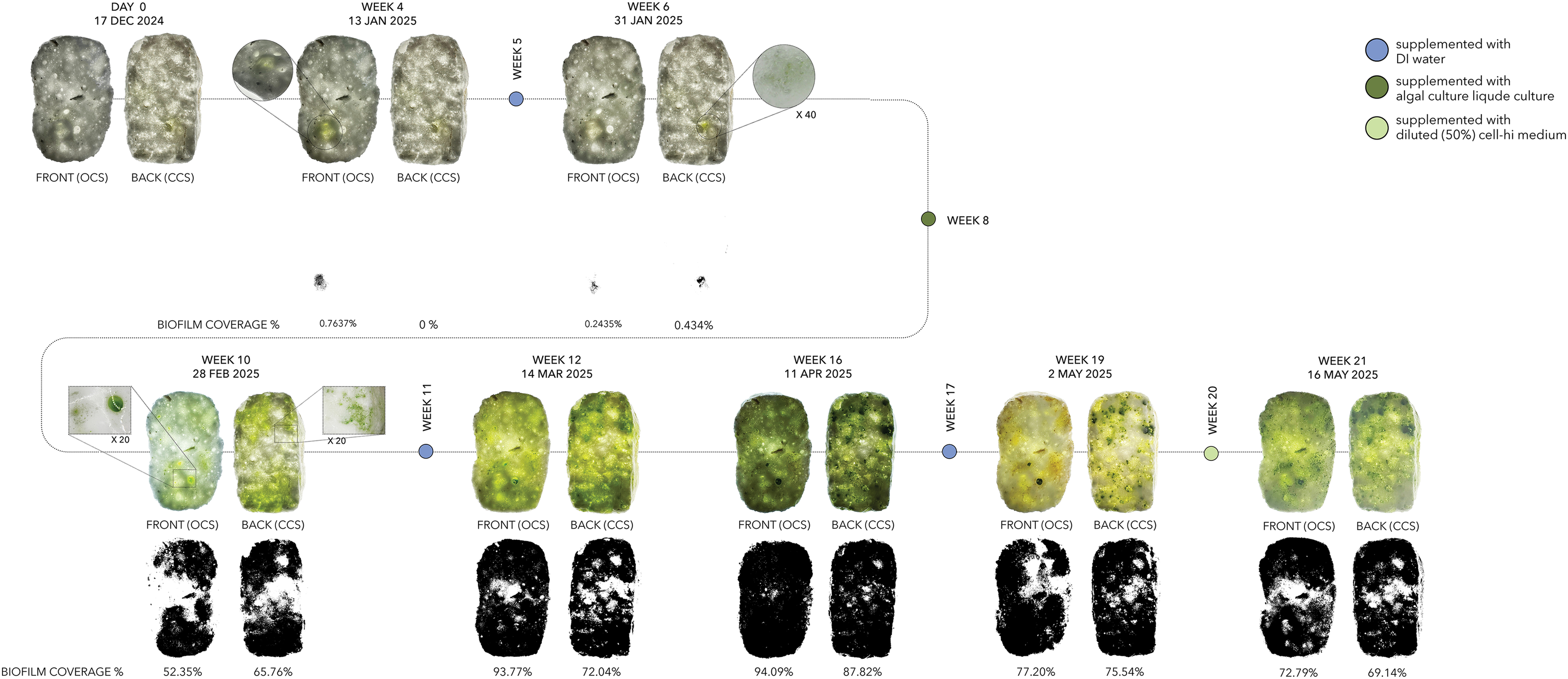
Foamed glass bioreceptivity experiment inoculated with C. vulgaris: 21-week growth timeline, ImageJ biofilm coverage analysis and 20
 $\! \times$
microscopy images under uncontrolled indoor incubation.

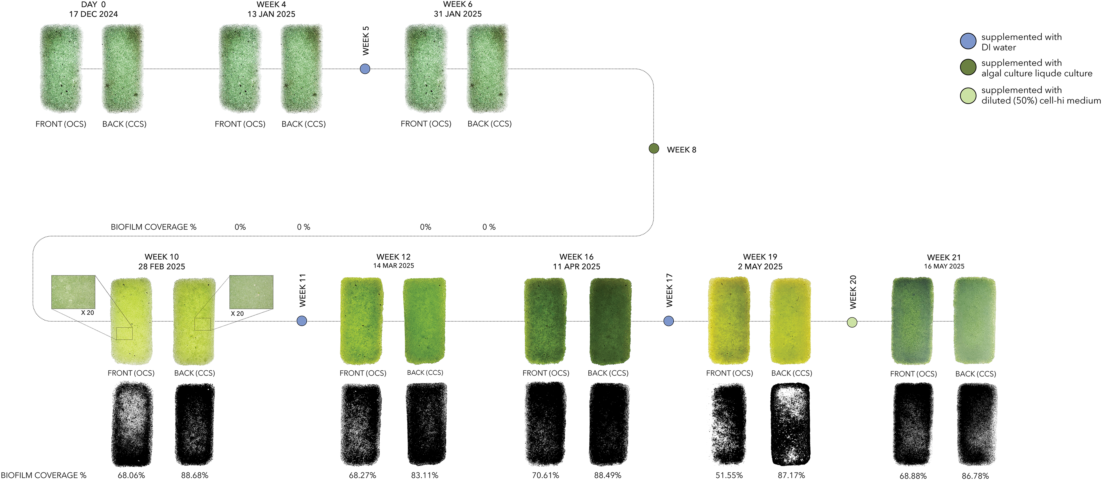
Sintered glass bioreceptivity experiment inoculated with C. vulgaris: 21-week growth timeline.

Figure 23. Long description
The figure tracks a foamed glass sample inoculated with C. vulgaris from day 0 to week 21 under uncontrolled indoor conditions. Front and back photographs show growth increasing from almost none at the start to dense green coverage by weeks 12 and 16, then shifting in colour and density by weeks 19 and 21. Early ImageJ coverage values are near zero, including 0.763% and 0% at day 0 and 0.243% and 0.434% at week 6. Later values are much higher: week 10 shows 52.35% front and 65.76% back; week 12 shows 93.77% and 72.04%; week 16 shows 94.09% and 87.82%; week 19 shows 77.20% and 75.54%; and week 21 shows 72.79% and 69.14%. The timeline includes treatment markers for DI water, algal culture liquid, and diluted Cell-Hi medium, plus 20x microscopy callouts.
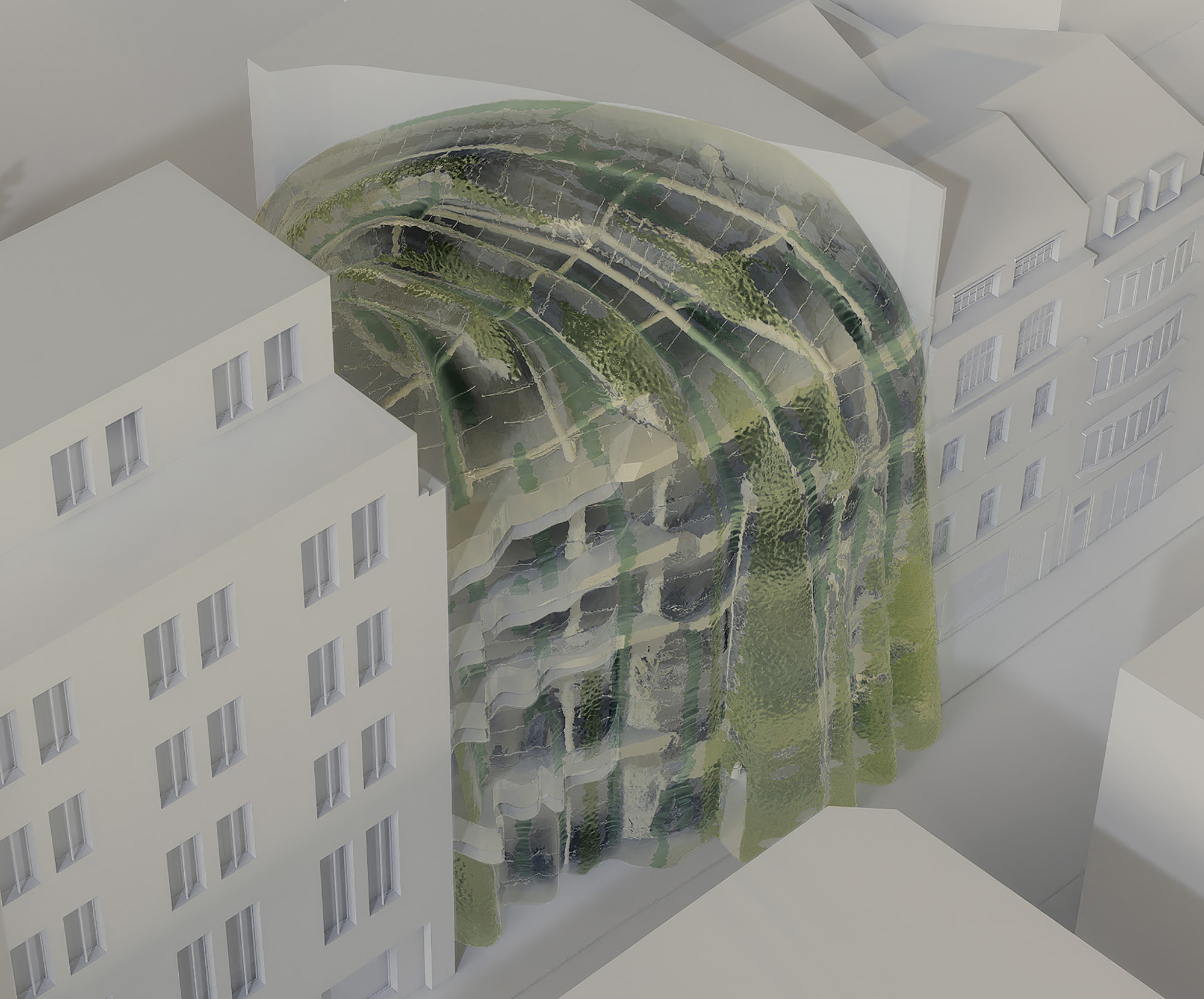
Render of a twelve-unit bioreceptive porous glass façade, illustrating dynamic seasonal variations in ecological growth. The visualisation is informed by observations from a 21-week bioreceptivity experiment conducted under uncontrolled indoor incubation conditions (Dhanesha et al. Reference Dhanesha, Fang, Alfraih, Salmane, Ruiz Rodriguez and Cruz2025).

Figure 24. Long description
The figure tracks a sintered glass sample inoculated with C. vulgaris from day 0 to week 21. The early front and back images at day 0, week 4, and week 6 show fairly even green surfaces but ImageJ biofilm coverage is recorded as 0%. By week 10 the sample appears brighter green and the coverage increases to 68.06% front and 88.68% back. Subsequent coverage values are 68.27% and 83.11% at week 12, 70.61% and 88.49% at week 16, 51.55% and 87.17% at week 19, and 68.88% and 86.78% at week 21. Treatment markers indicate additions of DI water, algal culture liquid, and diluted Cell-Hi medium.
This design demonstrates the potential for how the urban vertical space can be activated with weather and time beyond becoming a barrier and a hard edge. By softening this edge through material form and multi-species habitation, the design offers a new purpose of façades in a post-anthropocentric urban space (Figure 25). The idea of porous glass has potential for further development and can be used in other applications ranging from sound insulation to waste water treatment based on initial findings from thermal and water filtration studies. Polluted water would be filtered manually by the pore structure, while microalgal communities could support filtration at a microscale. Further extreme environment testing, biomass harvesting, strength testing, acoustic testing and further tuning of the porous glass structures would clarify the possibilities for this glass for other applications. By merging glassmaking with ecological thinking, this research charts a pathway towards bio-integrated materials that are temporal, expressive and alive, contributing to a future where architecture supports and enhances both human and microbial life.
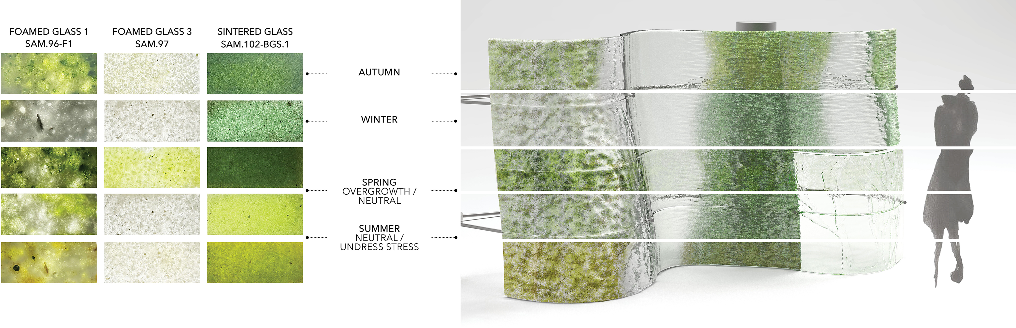
Overall façade render illustrating dynamic variations in ecological growth.

Figure 25. Long description
The figure links experimental observations to a facade visualisation. On the left, three columns of texture samples compare foamed glass 1 SAM.96-F1, foamed glass 3 SAM.97, and sintered glass SAM.102-BGS.1 across seasonal states. Labels identify autumn, winter, spring overgrowth or neutral, and summer neutral or under-stress conditions. On the right, a curved twelve-unit glass facade is divided into horizontal seasonal bands. Green growth varies from mottled pale coverage to denser vertical areas and yellow-green stressed tones. A human silhouette gives scale, showing the facade as a changing ecological surface rather than a fixed transparent envelope.
This project explored a novel approach to a material that has defined modern anthropocentric architecture. Porous, bioreceptive glass allows architecture to breathe and evolve over time, creating a proposal that challenges human control and maintenance over material and space. By inviting microbial interactions, the design begins to mitigate common problems of the built environment and introduces a new beauty of seasonal variation in colour, privacy and performance as the microecology meets human users and integrates into a larger ecosystem over time.
Data availability statement
The authors confirm that the data supporting the findings of this study are available within the article.
Acknowledgements
We would like to thank our Bio-Integrated Design programme directors and tutors: Brenda Parker, Marcos Cruz, Andreas Koerner, Javier Ruiz Rodriguez, Anete Krista Salmane, Tony Le and Nina Jotanovic for their continuous support and feedback throughout this project. Special acknowledgement to Tony Le for developing and sharing TOTO’s environmental plug-ins for Houdini. We extend our gratitude to our specialisation advisors Lydia Johnson, Edward Barrett and Paolo Bombelli, as well as to the B-Made team including Claudia Toma, Melis Van Den Berg and Hamish Veitch, for their technical assistance. We are also grateful to our Morley College glass course teacher Anna Chrysopoulo and technician Camilla Bridgewater for their guidance in glassmaking practices. We would also like to thank our Year 1 collaborators, Caitlin Bell, Chloe Perez and Clara Schmelter De Escobar. Finally, thank you to all our friends and family for their ongoing encouragement.
Author contributions
This research was conceptualised, equally by Roba Alfraih (RA), Juhi Dhanesha (JD), Xiaomeng Fang (XF), with support from Anete Krista Salmane (AKS), Andreas Koerner (AK) and Javier Ruiz Rodriguez (JRR). RA, JD and XF were responsible for investigation after agreeing on methodology with AKS for lab-related areas, and AK and JRR for design and computational areas. Microscopy of glass samples were performed by AKS, and all other visualisations by RA, JD and XF. This research was supervised by AKS, AK and JRR. The original draft was written by RA, JD and XF and was reviewed and edited by all authors. All authors approved the final submitted draft.
Financial support
This research received no specific grant from any funding agency, commercial or not-for-profit sectors.
Competing interests
None.
Ethical standards
Ethical approval and consent are not applicable as the research did not involve human or animal subjects.
 ±
 ±

 ±
 ±
 ×
 ×

 Open access

