I. INTRODUCTION
The recent development of the emerging dual-channel wireless communication systems has raised new challenges for the planar dual-band bandpass filter (DB-BPF) design, such as low loss, compact size, bandwidth (BW), and return loss (RL) control and adjustable transmission zeros (TZs). To meet these challenges, a large number of high-performance DB-BPF have been extensively studied. Among them, four types are preferable. In [Reference Chan and Chang1, Reference Li, Zhang, Feng, Song and Fan2], cross-coupling technology with hook-type feeding lines or source–load coupling were applied into the transversal topology so as to construct two independently controllable passbands and suppress the harmonic passband. However, they suffered from relatively large circuit size. In [Reference Gao and Zhang3, Reference Peng, Zhang, Fu, Wang and Leng4], a flexible quad-mode resonator was proposed to form low-loss and high-selectivity DB-BPFs. They featured compact size due to the usage of only a single multimode resonator, whereas, the BW, RL, and TZ control were difficult to be achieved in this type of DB-BPF, and the design process of quad-mode resonator was labor intensive. Additionally, using modified cascade-quadruplet topology and λ/4 resonators to form split-type DB-BPF was a good method to synthesize the DB-BPF [Reference Zhang and Zhu5] in theory. But, it was still hard to achieve the broad separation in the passbands in practice.
In order to realize BW and TZ control, separated electric and magnetic coupling (SEMC) technology, which can introduce TZs using just two resonators, was theoretically studied and experimentally verified in [Reference Ma, Ma and Yeo6–Reference Zhang, Zhu and Weerasekera8]. On the other hand, the feeding line structure is significant for SEMC filters. Specific to two order planar SEMC filter, capacitively coupled feeding line leads to a narrow passband as well as high loss but high selectivity since it is difficult to achieve higher level coupling [Reference Chu and Wang7–Reference Xiao, Zhu, Ma and Hong10] while inductively coupled feeding line results in lower loss, a wider BW selecting range but less selectivity [Reference Ma, Ma and Yeo6, Reference Chen, Chang, Tseng and Weng11].
In this paper, to overcome the difficulty of simultaneously achieving the BW and RL control in a compact multimode DB-BPF, we employ new dual-mode resonator-loaded resonators (DM-RLRs) and SEMC with the addition of the directly connected inductively coupled feeding taps to realize a new high-selectivity DB-BPF operating at 1.57 and 3.5 GHz. A simple strategy is also presented to guide the filter design. In comparison to the transversal-type DB-BPFs (e.g. [Reference Chan and Chang1, Reference Li, Zhang, Feng, Song and Fan2]), compact size is obtained due to the usage of the dual-mode resonator while the TZ, BW, and RL controllability are maintained. In contrast to quad-mode or multimode resonator-based DB-BPF (e.g. [Reference Gao and Zhang3, Reference Peng, Zhang, Fu, Wang and Leng4]), the proposed filter features BW and RL control because of the independently controllable SEMC and the flexible dual-mode resonant structure. In further comparison with split-type DB-BPF, the proposed one can provide the wide separation (1.57/3.5 GHz). The directly connected inductively coupled feeding taps are used to widen the BW selection range and lower the insertion loss (IL), which is common flaws in SEMC filters (e.g. [Reference Chu and Wang7–Reference Xiao, Zhu, Ma and Hong10]). To validate the analysis, the filter is fabricated and measured. The filter has IL of 0.9/0.9 dB at 1.57/3.5 GHz and four TZs close to the passbands. Furthermore, due to the utilization of SEMC and DM-RLR, TZs, BW, and RL of the filter are all controllable.
II. ANALYSIS OF THE DUAL-BAND FILTER
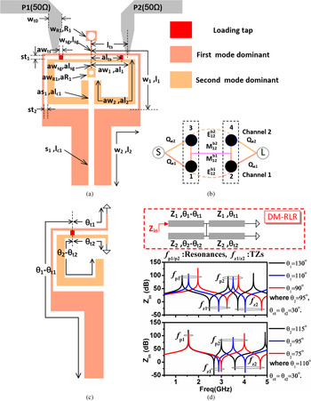
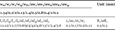
Figure 1(a) and Table 1 show the layout and dimensions of the presented DB-BPF on Rogers RO5880 substrate with relative dielectric constant of 2.2 and thickness of 0.508 mm. The proposed filter consists of two DM-RLRs, each one of which embeds two step-impedance resonators with a connected line. Corresponding coupling topology of the filter is depicted in Fig. 1(b). As shown, SEMC, which introduces two TZs for each passband [Reference Zhang, Zhu and Weerasekera8], is utilized between DM-RLRs. Specifically, the parallel-coupled line with a gap width of s 1 (or as 1) and a length of l c1 (or al c1) serves as a series electric coupling capacitor. Meanwhile, the grounded narrow line with a width of w sg (or aw sg ) and a length of l sg (or al sg ) is treated as a shunt magnetic coupling inductor. For the standalone bandpass channel, the coupling between two modes is composed of two coupling path, i.e. electric coupling and magnetic coupling. By suitably selecting them, the total coupling coefficient and the coupling zeros (TZs) can be designed. In addition, two passband channels share the same magnetic coupling structure and have different electric coupling paths. As a result, the BW and TZ are independently controlled.
(a) Geometry of the proposed DB-BPF. (b) Coupling schematic, (c) geometry of the standalone dual-mode resonator and (d) transmission line model of the proposed resonator and its typical input impedance in response with reference frequencies f 01 = 1.57 GHz (for θ 1 and θ t1) and f 02 = 3.5 GHz (for θ 2 and θ t2).

Dimensions for the proposed filter, refer to Fig. 1 (unit, mm).

An approximate equivalent model of the standalone resonator and the typical input impedance responses are given in Fig. 1(d), where the step-impedance transmission lines are modeled as the 50 Ω uniform-impedance transmission lines for simplification. As shown, two resonances and two TZs are visible. Also, both resonant frequencies are simultaneously adjusted by changing θ 1; however, changing θ 2 only affects the second resonant frequency. Thus, two resonant frequencies can be individually specified as desired by choosing θ 1 first and then θ 2. In other words, one can separately define two resonant frequencies by appropriately selecting l 1 and l 2, and then al 1 and al 2.
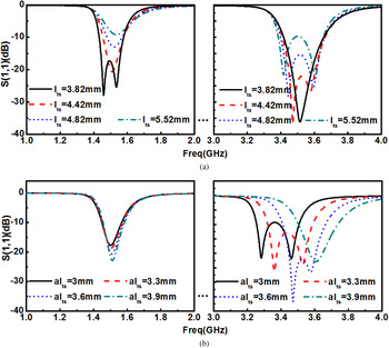
Moreover, in conjunction with two directly connected filter feeding taps, two connected lines in DM-RLRs with a width of aw ts and length of st 1, are utilized for RL control in the proposed filter, which improves the two passbands’ impedance match. For the parametric investigation, full-wave simulations are carried out. As shown in Fig. 2, RLs of two passbands can be separately determined by correctly positioning a pair of feeding taps and a pair of connecting lines. It is seen that changing l ts lead to RL changing for both two passbands. However, the variation of al ts only affects the second passband. That indicates one can separately control both bands’ RL, or external Q e1 and Q e2, by changing l ts first and then al ts . Noted that tuning al ts results in the second passband center frequency shift a little, which is mainly due to the length change between the loading tap (red part in Fig. 1(a)) and 50 Ω input/output feeding line (gray part in Fig. 1(a)). This frequency shift can be compensated by fine tuning al 1 and al 2.
RL variation with different connecting position (l ts and al ts ): (a) with different l ts and (b) different al ts .

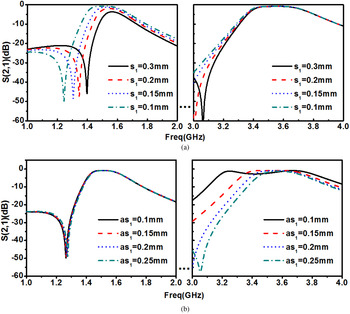
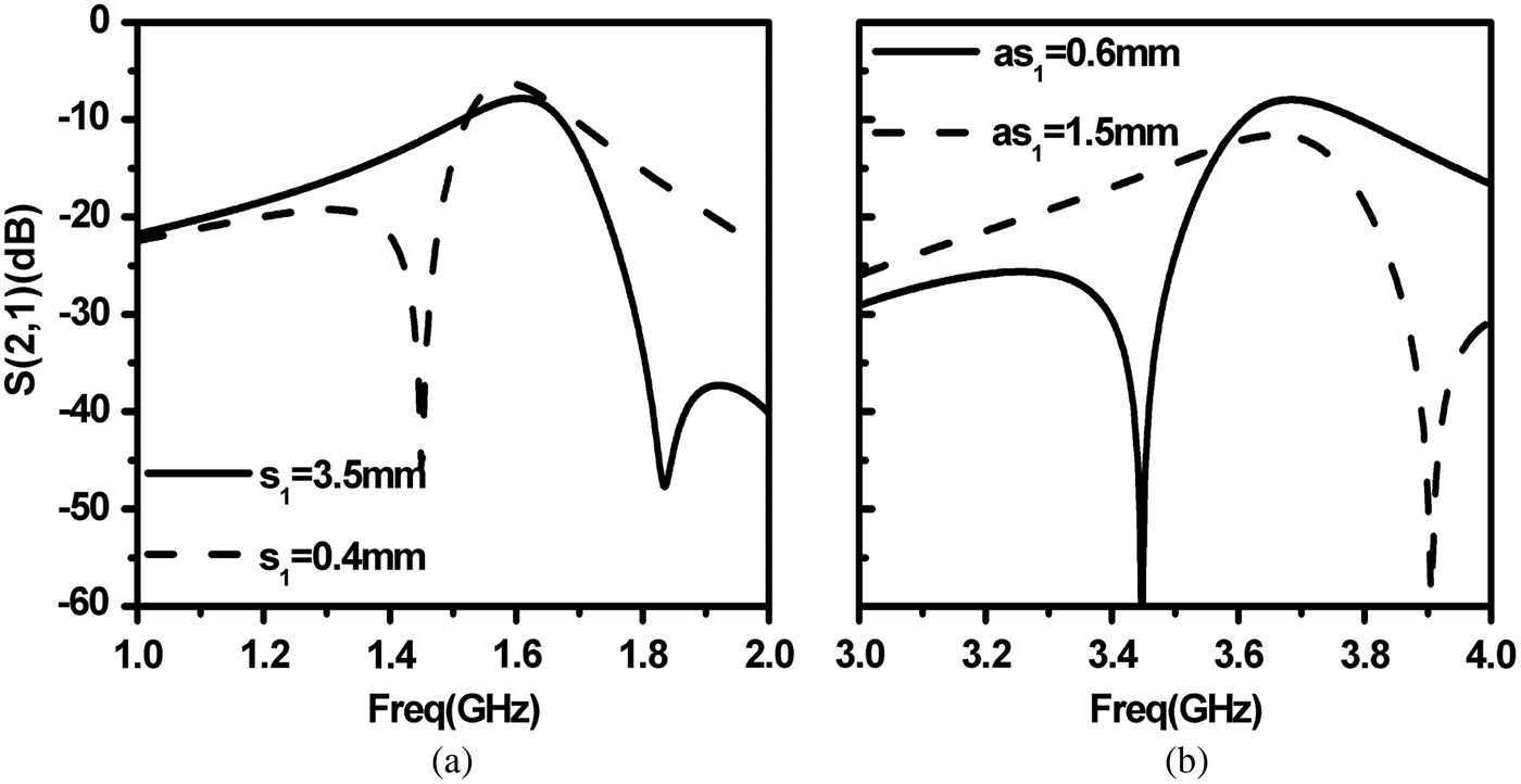
Apart from RL control, the total coupling coefficients are determined by the electric coupling and magnetic coupling, expressed by k = k m −k e [Reference Hong and Lancaster12] (where, k, k m , and k e stand for the total coupling, magnetic coupling, and electric coupling). Electric coupling, dominated by the series electric coupling capacitor, can be separately specified in this design. Therefore, total coupling control and the adjustable BW are obtained. As depicted in Fig. 3, with narrowing the gap (s 1), BW of the first passband increases and the second passband is kept unchanged, which means that the coupling in the first frequency channel is electric dominant, and the electric coupling strength can independently control total coupling. Similarly, the second passband BW can be tuned by changing as 1. Coupling in the second passband channel is electric dominant and independently controlled by the electric coupling strength (as 1).
BW variation with different electric couplings (s 1 and as 1): (a) with different s 1 and (b) different as 1.

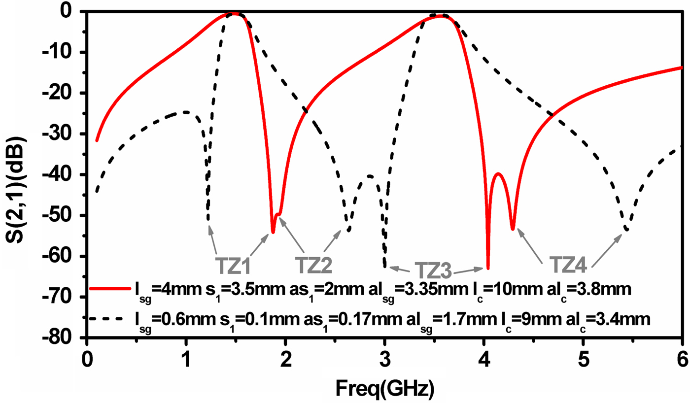
As demonstrated in [Reference Ma, Ma and Yeo6] and verified in [Reference Zhang, Zhu and Weerasekera8], SEMC with two single-mode resonators can generate a pair of controllable TZs. In this design, two pairs of TZs are introduced by SEMC between two DM-RLRs, and two TZs can be allocated from one side of the passband to the other by only changing the electric coupling strength. As shown in Fig. 4, by reducing electric coupling strength (increasing s 1 or as 1), total coupling turns into magnetic dominant coupling and the associated TZ shifts to the other side of the passband. Exploiting this characteristic, a DB-BPF with same passbands and dissimilar TZs distributions is realized to verify the TZ position reconfiguration. As depicted in Fig. 5, by increasing the magnetic coupling (lengthening l sg and al sg ) and reducing the electric coupling (enlarging s 1 for first band and as 1 for second band), the TZs distribution changes from both sides of each passband (black dash line) to all right sides of the passband (red solid line). The center frequency shift, due to coupling change, is compensated by the fine adjustment of DM-RLR (l c and al c ) (Fig. 6).
TZs shift induced by s 1 and as 1, (a) by s 1 and (b) by as 1.

TZs shift with different SEMC.

Design flow of the proposed filter.

III. DESIGN AND RESULTS
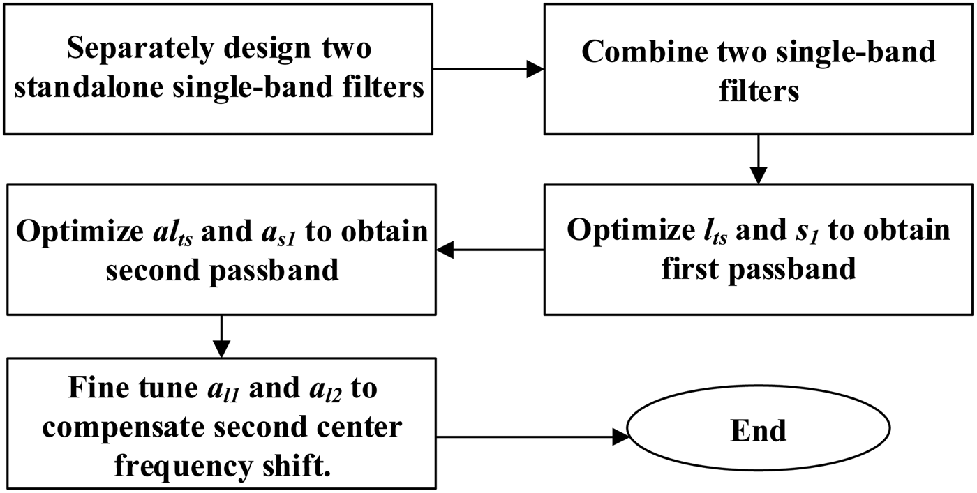
Since each frequency channel is approximately independent, as discussed above, the most efficient method to design the proposed DB-BPF is:
-
(1) Separately design the standalone single-band BPF, based on [Reference Chu and Wang7] to attain the initial values, with center frequencies of 1.57/3.5 GHz, and TZs of 1.3/2.5/2.75/6.75 GHz for this case.
-
(2) Employ the initial values to construct a DB-BPF. Optimize l ts and s 1 to approach the desire first passband.
-
(3) Finally, optimize al ts and a s1 to obtain the desire second passband and fine tune a l1 and a l2 to compensate the second center frequency shift.
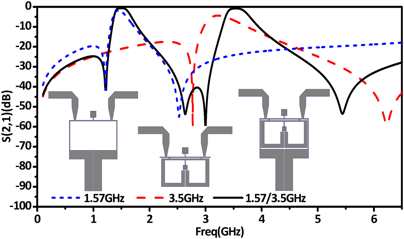
Figure 7 shows the response dissimilarity between the standalone filters and the DB-BPF, which is reasonably acceptable for the optimization process. The dissimilarity is due to the fact that the current of the standalone filter, flowing through the connected taps, is stronger than the current in DB-BPF. The current difference leads to the second band external Q decrease and center frequency shift. The different TZ positions are mainly caused by the second coupling and center frequency compensations.
Frequency responses with the standalone filters and the proposed filter.

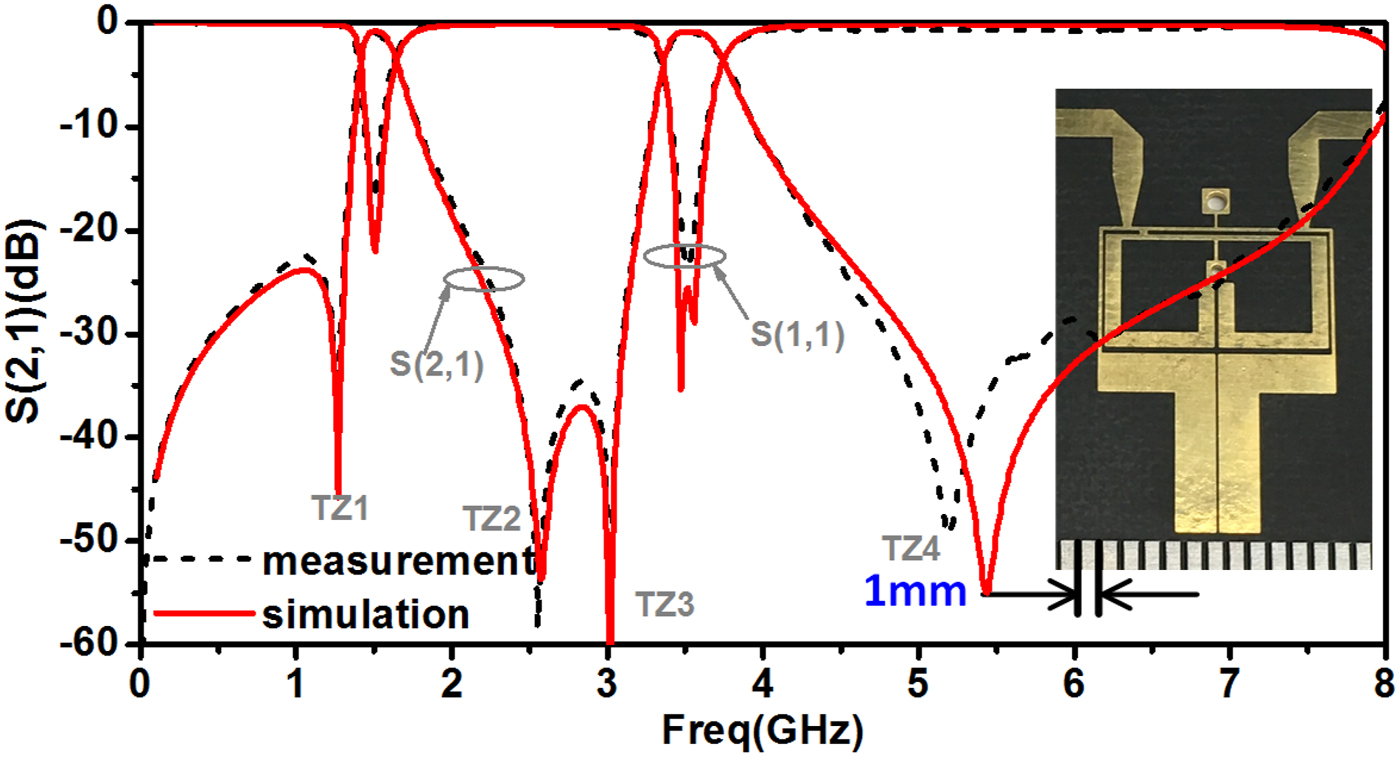
A demonstrative example is fabricated on Rogers RO5880 substrate and measured using National Instruments’ Vector Network Analyzer. The overall size of the filter is 0.12λ g × 0.08λ g, where λ g is the guided wavelength at the center frequency of the first band (1.57 GHz). Fig. 8 plots the comparison between simulation and measurement results with a photograph of the filter and a good agreement can be observed. As shown, two passbands are placed at 1.57 and 3.5 GHz with 3 dB BW (and fractional BW) of 240 MHz (15%) and 400 MHz (11.5%). The minimum measurement IL is 0.9 dB for both two passbands, and RL are 17 and 20 dB, respectively. In addition, the four controllable TZs, located at 1.3, 2.5, 3, and 5.2 GHz, can be seen.
Simulation and measurement results with photograph of the filter.

The comparison between other DB-BPF and this work is listed in Table 2. The proposed filter exhibits a compact size, high flexibility and low loss. Noted that in contrast to the typical SEMC filter, comparatively low IL is achieved due to the adoption of the directly connected inductively coupled feeding taps and relatively wide passbands. Besides, the independently controllable RL and BW make two well-matched and wide passbands to be realized easily, thus leading to lower IL, when the quality factor Q of each resonator is fixed.
Comparison with prior work (FC, BC, RC, and TC denote frequency, BW, RL, and TZ independently control; TZ denotes the number of TZ; * denotes this work; and NG denotes ‘not given’).

IV. CONCLUSION
A new DB-BPF using DM-RLRs and SEMC has been demonstrated in this paper. The coupling topology has been given, and the center frequency, TZ, BW, and RL control mechanism has been investigated and verified through full-wave simulation. A simple design strategy has been proposed to guide the demonstrative filter design. The other advantages of the filter containing compact size, high flexibility, high selectivity, and low loss have also been verified by the experimental results and the comparison with other works.
ACKNOWLEDGEMENT
The authors would like to express our sincere thanks to the editors and reviewers of this paper's manuscript for their constructive comments and suggestions, which greatly improved the quality of this paper. The first author Di also thanks Professor Zehui Mao from Nanjing University of Aeronautics and Astronautics for his helpful suggestions.
 Di Lu was born in Yunnan Province, China, in 1987. He received the B.S. degree in Electronic Engineering School from Chengdu University of Information and Technology (CUIT), China, in 2013. He now is pursuing towards the Ph.D. in the University of Electronic Science and Technology of China (UESTC). Since October 2015, he has been a Visiting Student with the University of Virginia (UVA). His main research interests are design microwave filters, tunable filters, frequency multipliers, mixers, millimeter-wave circuits, and radio frequency microelectromechanical systems (RF-MEMS).
 N. Scott Barker received the B.S.E.E. degree from the University of Virginia (UVA), Charlottesville, VA, USA, in 1994, and the M.S.E.E. and Ph.D. degrees in Electrical Engineering from the University of Michigan at Ann Arbor, Ann Arbor, MI, USA, in 1996 and 1999, respectively. From 1999 to 2000, he was a Staff Scientist with the Naval Research Laboratory. In 2001, he joined the Charles L. Brown Department of Electrical and Computer Engineering, UVA, where he is currently a Professor. He recently co-started the company Dominion Micro Probes Inc., Charlottesville, VA, USA, to develop the terahertz frequency wafer probe technology co-invented by his group at the UVA. He has authored or coauthored over 60 publications. His research interests include applying microelectromechanical systems (MEMS) and micromachining techniques to the development of millimeter-wave and terahertz circuits and components. Professor Barker has served on the MTT-21 Technical Committee on RF-MEMS since 2000 and was the Committee Chair from 2008 to 2011. He has also served for many years on the IEEE Microwave Theory and Techniques Society (IEEE MTT-S) International Microwave Symposium (IMS) Technical Program Review Committee. In 2011, he served on the Steering Committee, IEEE MTT-S IMS, Baltimore, MD, USA. He was the Technical Program Committee (TPC) Vice-Chair for the 2014 IEEE MTT-S IMS, Tampa, FL, USA. He was an Associate Editor for IEEE Microwave and Wireless Components Letters (2008–2010). He is currently an Associate Editor for the IEEE Transactions on Microwave Theory and Techniques. He was the recipient of the Charles L. Brown Department of Electrical and Computer Engineering New Faculty Teaching Award (2006) and the Faculty Innovation Award (2004), the 2003 National Science Foundation (NSF) CAREER Award, the 2000 IEEE Microwave Prize, and First and Second Place in the Student Paper Competition, IEEE MTT-S IMS.
 Xiao-Hong Tang received B.S. and Ph.D. degrees in Electromagnetism and Microwave Technology in UESTC. Now he is a Professor in UESTC. He has authored more than 100 journal and conference papers. He was also the recipient of several national and provincial awards. His research interests include microwave and millimeter communication, computational electromagnetics, etc.