1. Introduction
Birds execute precise manoeuvres, such as banking, braking, takeoff and landing, allowing them to navigate dense forests and urban environments. Micro-aerial vehicles (MAVs) are contemporary flying machines operating on the same scale as small birds, and are designed to carry out remote sensing and small payload delivery tasks in cluttered airspaces. Mimicking the manoeuvrability of birds, particularly the ability to land safely on narrow platforms, would allow them to complete these tasks effectively and efficiently. Though recent advances have been made in designing MAVs that can land on a perch (Reich, Wojnar & Albertani Reference Reich, Wojnar and Albertani2009; Doyle et al. Reference Doyle, Bird, Isom, Johnson, Kallman, Simpson, King, Abbott and Minor2011; Moore, Cory & Tedrake Reference Moore, Cory and Tedrake2014), existing MAVs still fall short in achieving the control, speed and precision of natural flyers in landing manoeuvres.
Birds are tremendously adept at controlled fast landings. Provini et al. (Reference Provini, Tobalske, Crandell and Abourachid2014) observed that zebra finches are able to decelerate from 15 to 7 body lengths per second in 0.15 s, entirely through aerodynamic means. Though the exact kinematic motion used by birds in perching manoeuvres varies between species (Berg & Biewener Reference Berg and Biewener2010; Provini et al.
Reference Provini, Tobalske, Crandell and Abourachid2014), one relatively simple motion is for a bird to pitch its wings continuously from near-horizontal to approximately
 $90^{\circ }$
angle of attack. Carruthers, Thomas & Taylor (Reference Carruthers, Thomas and Taylor2007) observed this motion in a steppe eagle and noted that the eagle gained altitude quickly during the landing phase, implying that large lift was produced. However, steady-state analysis predicted that the bird would lose lift at high angles of attack due to stall effects and reduced airspeed (Carruthers et al.
Reference Carruthers, Thomas, Walker and Taylor2010). When decelerating most rapidly and gaining height, the eagle entered a ‘rapid pitch-up phase’, in which it increased its angle of attack quickly while simultaneously spreading its wings.
To model the aerodynamics of the pitch-up wing motion in landing birds, we consider an aerofoil that rapidly increases its angle of attack while simultaneously decelerating. Though bird flight and landing is a three-dimensional problem, two-dimensional flow topologies often dominate in highly unsteady manoeuvres, as was shown by Garmann, Visbal & Orkwis (Reference Garmann, Visbal and Orkwis2013), and so we restrict ourselves to the two-dimensional pitch-up problem.
When an aerofoil pitches to high angles of attack, its frontal area rapidly increases. Rapid frontal area change of bodies in acceleratory manoeuvres results in significant added-mass effects, notably the recapture of added-mass energy as demonstrated by Weymouth & Triantafyllou (Reference Weymouth and Triantafyllou2012) in a shrinking cylinder and Weymouth & Triantafyllou (Reference Weymouth and Triantafyllou2013) in a squid-like deflating body. Rapid area change can also affect boundary-layer vorticity, causing sudden global shedding of vorticity in a vanishing aerofoil (Wibawa et al. Reference Wibawa, Steele, Dahl, Rival, Weymouth and Triantafyllou2012) and annihilation of boundary-layer vorticity in a shrinking cylinder (Weymouth & Triantafyllou Reference Weymouth and Triantafyllou2012).
These above studies have all looked at the fluid dynamics of a body with rapidly decreasing area. However, the case of a body with rapidly increasing frontal area has seen comparatively little attention, despite the potential to inform biological and technological designs. We show that the case of a pitching and decelerating aerofoil manipulates added-mass forces in a similar way to other rapid area change problems, but here the rapid increase in area bears unique performance challenges. Additionally, the rotation of the body produces lift and dynamic forces from boundary-layer separation, which have hitherto not been considered in rapid area change problems.
To study the unsteady dynamics of pitch-up during stopping manoeuvres, we first develop a low-order analytic model for the lift and drag force history on an aerofoil performing simultaneous pitch and deceleration. Such a model provides two benefits: (a) it identifies the salient features of the flow in order to understand physical mechanisms, and (b) it may be used to predict forces for MAV control at low computational cost.
Next, a complete set of numerical simulations and experimental studies are performed. The results demonstrate that a high-speed pitch and deceleration manoeuvre produces remarkable instantaneous lift and drag forces. By examining these results in the context of the analytic model, we determine that the majority of these forces can be attributed to (i) added-mass energy transfer between the fluid and aerofoil, and (ii) energy dissipated into the fluid by boundary-layer separation at the leading and trailing edges. These effects combine to achieve instantaneous and integrated forces compatible with the perching abilities of birds.
2. Analytic arguments
We first develop an analytic model of the forces produced during a pitch-up and stop manoeuvre to understand mechanisms of lift and drag generation in perching. Recent studies (Ol et al.
Reference Ol, Bernal, Kang and Shyy2009; Baik et al.
Reference Baik, Bernal, Granlund and Ol2012; Pitt Ford & Babinsky Reference Pitt Ford and Babinsky2013) have shown that classical potential flow theory from Wagner (Reference Wagner1925), Theodorsen (Reference Theodorsen1935) and von Kármán & Sears (Reference von Kármán and Sears1938) can provide reasonable predictions for the force histories of unsteady aerofoils, even for low-
 $\mathit{Re}$
cases with pronounced boundary-layer separation. These models have explanatory power as well, as they allow simple decomposition of the added-mass and circulatory forces. However, these potential flow models assume a small angle of attack and a planar wake (Wagner Reference Wagner1925; Theodorsen Reference Theodorsen1935; von Kármán & Sears Reference von Kármán and Sears1938), assumptions that are violated with rapid pitch-up to high
 ${\it\alpha}$
.
In this study we use an added-mass model valid for arbitrary angles of attack and pitch rate and derive a circulatory force model for highly separated flows around non-oscillatory aerofoils. The combined model has no free parameters, being dependent only on the prescribed kinematics of the pitching and decelerating aerofoil.
2.1. Model problem description and the shape change number
Consider an aerofoil with chord length
 $c$
that is initially at an angle of attack
 ${\it\alpha}=0^{\circ }$
and moving at a constant forward velocity
 $U_{0}$
. As a simple model of a bird’s wing during perching manoeuvres, this aerofoil section is made to rapidly rotate perpendicular to the translation direction, that is, to
 ${\it\alpha}=90^{\circ }$
, while simultaneously decelerating to a full stop over time period
 $T$
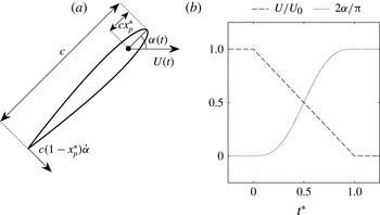
. This system and its kinematics are sketched in figure 1.
(a) A diagram showing the NACA0012 aerofoil section with chord
 $c$
and pivot point marked by a black dot at a distance
 $cx_{p}^{\ast }$
from the leading edge. The instantaneous angle of attack
 ${\it\alpha}(t)$
and velocity at the pivot
 $U(t)$
are prescribed. (b) The kinematics used in experiments and simulations, plotted as a function of non-dimensional time
 $t^{\ast }=t/T$
, where
 $T$
is the time period of the manoeuvre. The velocity is scaled by the initial value
 $U_{0}$
, while the angle is scaled by the final value
 ${\rm\pi}/2$
radians. Here,
 ${\it\alpha}$
is varied with a cycloidal function given in (2.6).

We parametrize the magnitude of the geometry change of the system with the shape change number
 $$\begin{eqnarray}{\it\Xi}=\frac{V}{U_{0}},\end{eqnarray}$$
where
 $V\equiv c/T$
is the average speed at which the frontal width of the aerofoil increases over the course of the manoeuvre. Defining the inline deceleration as
 $\dot{U}=U_{0}/T$
and substituting, we have
 ${\it\Xi}=V^{2}/(\dot{U}c)$
, matching the definition of shape change number in Weymouth & Triantafyllou (Reference Weymouth and Triantafyllou2013). The parameter
 ${\it\Xi}$
acts as a measure of the unsteadiness of the problem, similar to the reduced frequency,
 $k={\rm\pi}fc/U_{0}$
, where
 $f$
is a circular frequency. We choose to use
 ${\it\Xi}$
in this work to emphasize that the motion is not cyclic and that the change in frontal area is fundamental to the perching problem.
For an aerofoil rotating from
 ${\it\alpha}=0^{\circ }$
to
 $90^{\circ }$
and simultaneously decelerating from
 $U=U_{0}$
to 0 in time
 $T$
, the magnitudes of
 $\dot{{\it\alpha}}$
,
 $\ddot{{\it\alpha}}$
and
 $\dot{U}$
can be estimated as
 $$\begin{eqnarray}\dot{{\it\alpha}}\propto \frac{1}{T}=\frac{U_{0}}{c}{\it\Xi},\quad |\ddot{{\it\alpha}}|\propto \frac{1}{T^{2}}=\frac{U_{0}^{2}}{c^{2}}{\it\Xi}^{2},\quad \dot{U}\propto \frac{U_{0}^{2}}{c}{\it\Xi},\end{eqnarray}$$
so long as
 $U$
and
 $\dot{{\it\alpha}}$
are continuous functions in time. The relations given by (2.2) show that
 ${\it\Xi}$
parametrizes the rate of rotation, rotational acceleration and translational acceleration.
2.2. Added-mass manipulation through frontal area change
This change in frontal area has pronounced consequences on the added-mass forces produced during the manoeuvre. These can be described from very simple relations, and merit a brief discussion for readers unfamiliar with the topic.
Consider a body accelerating in one dimension but allowed to modify its frontal area in time. As the body expands, it displaces more fluid, effectively increasing its added mass. Conversely, a reduction in frontal area would decrease the added mass in time. The one-dimensional added-mass force can be written as
 $$\begin{eqnarray}F_{AM}=-\frac{\partial }{\partial t}(m_{a}U)=-{\dot{m}}_{a}U-m_{a}\dot{U},\end{eqnarray}$$
where
 $m_{a}$
is the instantaneous added mass of the body. The terms on the right-hand side arise respectively from the rate of change of the added mass (
 ${\dot{m}}_{a}U$
) and from the acceleration of the added mass (
 $m_{a}\dot{U}$
). Weymouth & Triantafyllou (Reference Weymouth and Triantafyllou2013) found that the added mass of an accelerating prolate spheroid decreased during body deflation (
 ${\dot{m}}_{a}<0$
). This had a twofold effect in view of (2.3). The first was in achieving additional thrust by recovering added-mass energy (the
 $-{\dot{m}}_{a}U$
term). The second was in reducing parasitic drag throughout the manoeuvre (the
 $-m_{a}\dot{U}$
term). Both effects were beneficial for the performance goal of high acceleration.
However, there is a tradeoff for an expanding body when deceleration is desired. On the one hand, addition of added mass from frontal area expansion (
 ${\dot{m}}_{a}>0$
) would create drag through
 $-\dot{m_{a}}U$
. But this would also increase the total added mass in time, making it difficult to stop the body late in the manoeuvre by producing a net thrust through
 $-m_{a}\dot{U}$
. The sudden change in the direction of forces would tend to yield an uncontrolled perching manoeuvre, which is not observed (Green & Cheng Reference Green and Cheng1998; Carruthers et al.
Reference Carruthers, Thomas and Taylor2007; Berg & Biewener Reference Berg and Biewener2010). In the next two sections we extend the simple one-dimensional force model (2.3) by discussing the effects of rotation on the added-mass force, and by modelling the circulation forces created through the production of vorticity.
2.3. The added-mass force
The general added-mass force normal to a flat-plate aerofoil in translation and rotation at general angles of attack can be developed in a number of ways. The general boundary function method of Milne-Thomson (Reference Milne-Thomson1968) can be applied to give the potential solution
 ${\it\phi}$
for the case of a rotating and accelerating flat plate, from which the added-mass force coefficient is determined to be
 $$\begin{eqnarray}C_{F{\it\phi}}=\frac{{\rm\pi}c}{2U_{0}^{2}}[\dot{{\it\alpha}}\cos ({\it\alpha})U+\sin ({\it\alpha})\dot{U}+c\ddot{{\it\alpha}}(1/2-x_{p}^{\ast })],\end{eqnarray}$$
where
 $cx_{p}^{\ast }$
is the distance from the leading edge of the aerofoil to the pivot location. Xia & Mohseni (Reference Xia and Mohseni2013) use an alternative rotating reference frame argument to develop the same added-mass force expression. In the context of (2.3), the first term in brackets in (2.4) arises from the time rate of change of added mass, and the second from linear acceleration of added mass. The final term arises from rotational acceleration absent in the one-dimensional analogy.
For the perching manoeuvre, we apply the relations given by (2.2) and see that the added-mass force in (2.4) should scale by no more than
 ${\it\Xi}^{2}$
. We also note that the added-mass force disappears as
 ${\it\Xi}\rightarrow 0$
(the quasi-steady limit), as expected.
We next study (2.4) through a prescribed set of kinematics representing simultaneous deceleration and pitch-up to large
 ${\it\alpha}$
, relevant to perching manoeuvres in birds (Carruthers et al.
Reference Carruthers, Thomas and Taylor2007):
 $$\begin{eqnarray}\displaystyle & U=U_{0}(1-t^{\ast }), & \displaystyle\end{eqnarray}$$
 $$\begin{eqnarray}\displaystyle & \displaystyle {\it\alpha}(t)=\frac{{\rm\pi}}{2}\left[t^{\ast }-\frac{\sin (2{\rm\pi}t^{\ast })}{2{\rm\pi}}\right], & \displaystyle\end{eqnarray}$$
 $t^{\ast }=t/T=tV/c$
is the non-dimensional time (
 $0\leqslant t^{\ast }\leqslant 1$
). We also set
 $x_{p}^{\ast }=1/6$
. The resultant added-mass lift and drag,
 $$\begin{eqnarray}\displaystyle & C_{l{\it\phi}}=C_{F{\it\phi}}\cos {\it\alpha}, & \displaystyle\end{eqnarray}$$
 $$\begin{eqnarray}\displaystyle & C_{d{\it\phi}}=C_{F{\it\phi}}\sin {\it\alpha}, & \displaystyle\end{eqnarray}$$
 $C_{F{\it\phi}}$
and
 ${\it\alpha}$
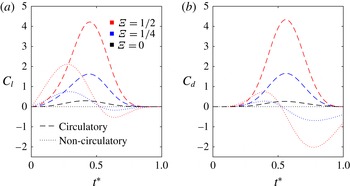
. The added-mass force generates a significant parasitic thrust late in the manoeuvre, as discussed in § 2.2. The magnitude of the force is increased by the rotational acceleration appearing in (2.4), as rotational acceleration must be positive early in the manoeuvre to begin rotation (generating lift) and negative late in the manoeuvre to halt rotation (generating thrust). However, the perfect recovery of added-mass energy implied by (2.3) requires the kinetic energy of the entire fluid domain to be zero at the end of the manoeuvre, and therefore neglects circulatory forces due to the vortex wake.
Predicted circulatory ((2.14), dashed lines) and added-mass ((2.7) and (2.8), dotted lines) forces for the kinematic values given by (2.5) and (2.6). For lift, added-mass forces are most pronounced early in the manoeuvre but are quickly surpassed by circulatory forces. Peak circulatory drag dominates peak added-mass drag; however, the parasitic thrust from the added-mass force overwhelms circulatory contributions late in the manoeuvre at high
 ${\it\Xi}$
. As
 ${\it\Xi}\rightarrow 0$
, added-mass lift and drag approach zero.

2.4. Circulatory forces
Von Kármán & Sears (Reference von Kármán and Sears1938) demonstrated that an aerofoil wake and bound circulation could be modelled as a superposition of equal-strength counter-rotating point-vortex pairs. Each vortex pair in two dimensions has an associated hydrodynamic impulse,
 $$\begin{eqnarray}\boldsymbol{I}={\it\Gamma}\hat{\boldsymbol{z}}\times \boldsymbol{r},\end{eqnarray}$$
where
 ${\it\Gamma}$
is the circulation of one of the vortices,
 $\hat{\boldsymbol{z}}$
is a unit vector pointing normal to the plane, and
 $\boldsymbol{r}$
is the displacement vector from the positive to negative vortex centre. Since the circulatory force is related to the fluidic impulse by
 $\boldsymbol{F}_{{\it\gamma}}=-{\it\rho}(\text{d}\boldsymbol{I}/\text{d}t)$
, this results in the following relation for the circulatory contributions to forces on the body:
 $$\begin{eqnarray}\boldsymbol{F}_{{\it\gamma}}=-{\it\rho}\dot{{\it\Gamma}}\hat{\boldsymbol{z}}\times \boldsymbol{r}-{\it\rho}{\it\Gamma}\hat{\boldsymbol{z}}\times \dot{\boldsymbol{r}}.\end{eqnarray}$$
Equation (2.10) shows that vortex forces can be altered through the addition or elimination of circulation to or from the vortex dipole (
 $\dot{{\it\Gamma}}$
) and by the convection of one vortex relative to the other (
 ${\dot{r}}$
).
Analysis of the convective term in (2.10) is generally accomplished either by assuming the wake is stationary relative to the undisturbed fluid, which leads to a lift proportional to
 $U{\it\Gamma}$
as in von Kármán & Sears (Reference von Kármán and Sears1938), or by numerically tracking the distribution of vorticity in the wake. As the transient perching flow is certain to be non-stationary, and as the goal of the model is to develop an understandable description of the forcing to complement further numerical and experimental testing, neither of these options is satisfactory. Moreover, in the limit of a very high-speed manoeuvre, it is reasonable to assume that the flow simply will not have time to convect significantly, making this term negligible; whereas in the limit of a very slow manoeuvre with significant vortex shedding, the average value of
 ${\it\Gamma}$
in the wake will tend to zero, and therefore so will the mean convective force.
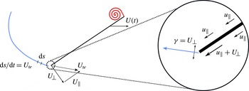
Therefore, for simplicity, we focus solely on the generation term. Pitt Ford & Babinsky (Reference Pitt Ford and Babinsky2013) showed that net bound circulation was negligible for a flat-plate aerofoil undergoing a rapid acceleration; nearly all circulation was contained in the trailing-edge wake and leading-edge vortex (LEV). For this reason, we suppose that all circulation is added to the flow at the leading and trailing edges such that, at the instant that vorticity is added to the flow, the two small resulting vortices are separated by one chord length (figure 3). From (2.10), the resultant force per unit length due to the generation of vorticity is
 $$\begin{eqnarray}F_{{\it\gamma}}=-{\it\rho}c\dot{{\it\Gamma}},\end{eqnarray}$$
where
 $\dot{{\it\Gamma}}$
is the rate of (absolute) circulation shed into the flow at one edge and the direction of force is normal to the chord towards the suction side.
Sketch of the circulation production model. Velocity on the pressure side increases by an amount equal to
 $U_{\bot }$
while the separated fluid on the suction side does not. This differential speed leads to a circulation per unit length
 ${\it\gamma}={\rm\Delta}u_{\Vert }=U_{\bot }$
at the trailing edge. The negative vorticity in the wake, shown here as a light grey line (blue online), increases in length at the trailing edge at a rate equal to the trailing-edge speed:
 $\text{d}s/\text{d}t=U_{te}$
. This results in the total rate of change of circulation
 $\dot{{\it\Gamma}}=(\text{d}{\it\Gamma}/\text{d}s)\,(\text{d}s/\text{d}t)=U_{te}U_{\bot }$
. The circulation of the LEV increases by an equal and opposite amount in accordance with Kelvin’s theorem.

We can estimate the production of circulation at the trailing edge of the aerofoil by assuming that the fluid is detached on the suction side, such that the chord-normal component of the velocity
 $u_{\bot }$
only slowly decays with increased distance from the foil. In contrast, the velocity field on the high-pressure side will quickly decay as in the potential flow solution. Incompressibility of the flow therefore requires that the tangential velocity
 $u_{\Vert }$
on the high-pressure side increases by an amount equal to the normal velocity of the aerofoil whereas the suction side does not (figure 3). The velocity difference across the aerofoil implies that the fluid in the region of the trailing edge should be modelled as a vortex sheet with strength
 $$\begin{eqnarray}{\it\gamma}={\rm\Delta}u_{\Vert }=U_{\bot },\end{eqnarray}$$
where
 $U_{\bot }$
is the velocity of the trailing edge of the aerofoil normal to the chord. Over a time
 $\text{d}t$
this sheet streams off the aerofoil as the trailing edge covers a distance
 $\text{d}s=U_{te}\,\text{d}t$
. As
 $\text{d}{\it\Gamma}={\it\gamma}\,\text{d}s$
, the production of circulation in the fluid is therefore
 $$\begin{eqnarray}\dot{{\it\Gamma}}=U_{te}U_{\bot }.\end{eqnarray}$$
From (2.11), this results in a force coefficient of
 $$\begin{eqnarray}C_{F{\it\gamma}}=\frac{2U_{te}U_{\bot }}{U_{0}^{2}}.\end{eqnarray}$$
It is informative to expand these speeds in terms of the aerofoil kinematics. We have
 $$\begin{eqnarray}\displaystyle & U_{te}=\sqrt{U^{2}+2U{\it\eta}_{p}^{\ast }c\dot{{\it\alpha}}\sin {\it\alpha}+{\it\eta}_{p}^{\ast 2}c^{2}\dot{{\it\alpha}}^{2}}, & \displaystyle\end{eqnarray}$$
 $$\begin{eqnarray}\displaystyle & U_{\bot }=U\sin {\it\alpha}+{\it\eta}_{p}^{\ast }c\dot{{\it\alpha}}, & \displaystyle\end{eqnarray}$$
 $$\begin{eqnarray}\displaystyle & {\it\eta}_{p}^{\ast }\equiv 1-x_{p}^{\ast }. & \displaystyle\end{eqnarray}$$
 $\dot{{\it\alpha}}\propto {\it\Xi}$
from (2.2), when
 ${\it\Xi}\gg 1$
we have
 $F_{{\it\gamma}}\rightarrow {\it\rho}c({\it\eta}_{p}^{\ast }c\dot{{\it\alpha}})^{2}$
, showing that the translational component becomes negligible and that the production of circulation is dominated by the rotation of the sharp trailing edge. Also note that, as
 ${\it\Xi}\rightarrow 0$
,
 $F_{{\it\gamma}}\rightarrow {\it\rho}c\sin ({\it\alpha})U^{2}$
, showing that this circulatory model has a quasi-steady contribution. Unlike the steady Kutta lift force, which is valid for attached flows at low angles of attack, this mean force estimate is chord-normal and assumes fully detached flow.
Returning to figure 2, we note that the circulatory forces increase with
 ${\it\Xi}$
, and the peak lift and drag at
 ${\it\Xi}=1/2$
are
 ${\sim}10$
times the steady-state values. Because the force is due solely to the production of leading- and trailing-edge vorticity, energy is transferred in only one direction – from the aerofoil to the wake.
2.5. The net force on an aerofoil
By superimposing the added-mass (2.4) and circulatory (2.14) contributions we arrive at our analytic model of the force coefficient:
 $$\begin{eqnarray}\displaystyle C_{F} & = & \displaystyle \frac{2}{U_{0}^{2}}[\sin ({\it\alpha})U+c\dot{{\it\alpha}}(1-x_{p}^{\ast })]\sqrt{U^{2}+2Uc\dot{{\it\alpha}}(1-x_{p}^{\ast })\sin ({\it\alpha})+c^{2}\dot{{\it\alpha}}^{2}(1-x_{p}^{\ast })^{2}}\nonumber\\ \displaystyle & & \displaystyle +\,\frac{{\rm\pi}c}{2U_{0}^{2}}[\dot{{\it\alpha}}\cos ({\it\alpha})U+\sin ({\it\alpha})\dot{U}+c\ddot{{\it\alpha}}(1/2-x_{p}^{\ast })].\end{eqnarray}$$
This model depends only on two geometric and two kinematic (time-dependent) parameters: the chord length
 $c$
, the pivot point
 $x_{p}^{\ast }$
, the translational speed
 $U(t)$
and the angle of attack
 ${\it\alpha}(t)$
.
We next present our experimental and numerical investigations of the two-dimensional perching problem. We then discuss the results in the context of our simplified analytic model.
3. Experimental set-up
To quantitatively assess the fluid dynamics induced by rapid perching, we performed a set of experimental manoeuvres by varying
 ${\it\Xi}$
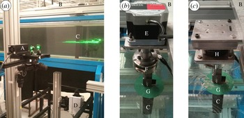
using a towed NACA0012 aerofoil. Forces on the aerofoil were measured directly, and the velocity field was measured using particle image velocimetry (PIV) to evaluate circulatory effects. All experiments were performed in a free-surface towing facility at the University of Calgary. The water channel test section is 38.6 cm wide, and water level was maintained at a 42 cm depth. An aluminium NACA0012 aerofoil with 48 mm chord was positioned midway between the channel walls in a vertical orientation (figures 4
b and 2
c) and pierced the free surface from above. The aerofoil tip was 4 mm from the bottom of the test section to reduce tip effects. Thus the aerofoil had a submerged span of 416 mm and an aspect ratio of 8.7. The high aspect ratio further justifies the assumption of two-dimensional flow. A plastic skim plate of 112 mm diameter and 2 mm thickness was secured to the aerofoil and sat 3 mm below the water surface. This skim plate eliminated the formation of free-surface funnel vortices. The aerofoil was attached at one end to an ATI Gamma force/torque balance. The force balance was attached to a two-phase stepper motor with
 $0.9^{\circ }$
step angle. The pitching axis was
 $c/6$
from the leading edge. The apparatus was fixed to a Parker linear traverse, which ran along the length of the water channel.
(a) PIV set-up, showing a laser (A) projecting a laser sheet into the water tunnel from the side. The aerofoil (C), attached to the traverse stage (B), was translated through the laser sheet with prescribed kinematics. A Photron SA4 high-speed camera (D) filmed the manoeuvre through the glass bottom of the water channel. (b) The aerofoil attachment used for PIV and force measurements. The aerofoil (C) was attached to a six-component force/torque balance (F), which in turn was attached to a stepper motor (E). A plastic skim plate (G) prevented the formation of free-surface vortex funnels. The entire attachment was secured to the stage of a linear traverse (B), which sat on top of the water channel. (c) The aerofoil attachment used for steady force measurements. The same aerofoil (C), skim plate (G) and force balance (F) attachment as the unsteady set-up (b) was used. The force balance was attached to a rotational stage (H), which in turn was secured to the traverse stage (B).

The aerofoil first established a steady-state condition at
 ${\it\alpha}=0^{\circ }$
and speed
 $U_{0}=0.45~\text{m}~\text{s}^{-1}$
for at least 10 chord lengths before beginning rotation and deceleration. The Reynolds number at the beginning of the manoeuvre is therefore
 $\mathit{Re}=U_{0}c/{\it\nu}=22\,000$
, in the range relevant for small highly manoeuvrable birds. The start of unsteady kinematics was synchronized through an induction sensor at a fixed position on the traverse track, which detected the passing traverse stage. The kinematics follow those shown in figure 1 and equations (2.5) and (2.6).
3.1. Force measurements
Force measurements were taken at a 1000 Hz sample rate (16 bit sample depth). Recorded force data were averaged across 10 trials for each test case. The force measurements were repeated for the same kinematics once water had been drained from the channel in order to measure the non-hydrodynamic inertia of the system. Force data were transformed from an aerofoil-fixed frame to a laboratory-fixed frame, and the inertia was subtracted. The transformed data were further smoothed with a two-degree Butterworth low-pass filter. Filter frequency cutoff was chosen as 4 Hz for
 ${\it\Xi}=1/32$
and 10 Hz for
 ${\it\Xi}=1/2$
. Filter frequency cutoffs for intermediate
 ${\it\Xi}$
were determined by interpolating linearly between these values. This method was found to best preserve peaks while eliminating noise. To avoid time shifting of data, a forward–backward filtering technique was used. Force measurements were synchronized through the same induction sensor on the traverse track that triggered the deceleration.
Force measurements were also performed on the same aerofoil at a constant speed (
 $0.45~\text{m}~\text{s}^{-1}$
) and constant angle of attack. Here,
 ${\it\alpha}$
was varied between trials from
 $0^{\circ }$
to
 $5^{\circ }$
with
 $1^{\circ }$
increments, and from
 $5^{\circ }$
to
 $90^{\circ }$
with
 $5^{\circ }$
increments using a rotational stage (figure 4
c). The same measurements were performed for negative values of
 ${\it\alpha}$
to assess the symmetry of the set-up. These measurements were used to make quasi-steady predictions (
 ${\it\Xi}=0$
). Quasi-steady force coefficients were computed as
 $$\begin{eqnarray}C_{F}=\frac{2F}{{\it\rho}cS}\frac{U({\it\alpha})^{2}}{U_{0}^{4}},\end{eqnarray}$$
where
 $F$
is the measured force,
 $U({\it\alpha})$
is the speed of the aerofoil at a particular angle of attack in the unsteady case, and
 $U_{0}$
is the starting speed.
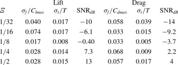
To estimate the uncertainty of force measurements, the standard deviations of peak lift and drag between trials at each shape change number were measured. Signal-to-noise ratios were also calculated between filtered and ensemble-averaged data. Values are presented in table 1. The measured standard deviations of peak forces do not exceed 8 % of the corresponding average peak value, and the measured standard deviations of the time of peak forces do not exceed 4 % of the corresponding period of deceleration and pitch.
Estimates of uncertainty and signal-to-noise ratios (
 $\text{SNR}_{dB}$
, in decibels) for lift and drag. Here,
 ${\it\sigma}_{f}$
is the measured standard deviation of the peak force coefficient across trials, and
 ${\it\sigma}_{t}$
is the measured standard deviation of peak force time;
 $C_{lmax}$
and
 $C_{dmax}$
are the peak average lift and drag coefficients, respectively.

3.2. Particle image velocimetry
A 1 W continuous-wave laser (
 ${\it\lambda}=532~\text{nm}$
) projected a laser sheet into a plane orthogonal to the aerofoil (figure 4
a). This laser sheet was 21.1 cm above the water channel floor. The water was seeded with silver-coated hollow glass spheres of
 $100~{\rm\mu}\text{m}$
diameter. These particles have a Stokes number of approximately
 $2.4\times 10^{-3}$
, and therefore were assumed to accurately follow the fluid flow. As the aerofoil passed through the laser sheet, a Photron SA4 high-speed camera (
 $1024~\text{pixel}\times 1024~\text{pixel}$
resolution) captured images at 250 frames per second. PIV data collection was synchronized with the same induction sensor on the traverse track that triggered the profile deceleration.
Raw images were preprocessed with a min/max contrast normalization filter of size
 $14~\text{pixel}\times 14~\text{pixel}$
and a sliding-average subtraction filter of 50 pixel width. Velocity fields were calculated with a multigrid/multipass cross-correlation algorithm using DaVis software (LaVision, v8.1.2). Velocity fields were averaged across nine trials.
Based on the random error estimates of Raffel et al. (Reference Raffel, Willert, Wereley and Kompenhans2007), pixel displacement uncertainty is taken as
 ${\it\delta}s=\pm 0.1~\text{pixel}$
. Propagation of uncertainty through velocity and vorticity with 4 pixel spacing between velocity vectors yields
 $$\begin{eqnarray}{\it\delta}{\it\omega}^{\ast }=\frac{{\it\delta}s}{4{\rm\Delta}t\sqrt{n}}\,\frac{c}{U_{0}},\end{eqnarray}$$
where
 ${\it\delta}{\it\omega}^{\ast }$
is the non-dimensional uncertainty in vorticity,
 ${\rm\Delta}t$
is the time interval between frames and
 $n$
is the number of trials. Given (3.2), the uncertainty in non-dimensional vorticity for PIV measurements is estimated as
 ${\it\delta}{\it\omega}^{\ast }=\pm 0.2$
.
4. Numerical method
A set of two-dimensional incompressible Navier–Stokes simulations of the model perching problem introduced in § 2 were used to provide high-resolution data with the exact kinematics of this challenging test case. To further this aim, the Reynolds number based on the initial steady speed
 $U_{0}$
is set to
 $\mathit{Re}=2000$
in these simulations to ensure that the model flow remains fully two-dimensional near the foil and the vortex structures remain clean and easily identifiable.
The boundary data immersion method (BDIM), a robust immersed boundary method suitable for dynamic fluid–structure interaction problems detailed in Weymouth & Yue (Reference Weymouth and Yue2011) and Maertens & Weymouth (Reference Maertens and Weymouth2015), was used for this purpose. Briefly, the full Navier–Stokes equations and the prescribed body kinematics shown in figure 1 are convolved with a kernel of support
 ${\it\epsilon}=2h$
, where
 $h$
is the grid spacing. The integrated equations are valid over the complete domain and allow for general solid-body dynamics to be simulated. Previous work has validated this approach for a variety of dynamic rigid-body problems such as accelerating aerofoils (Wibawa et al.
Reference Wibawa, Steele, Dahl, Rival, Weymouth and Triantafyllou2012) and deforming-body problems (Weymouth & Triantafyllou Reference Weymouth and Triantafyllou2013). In Maertens & Weymouth (Reference Maertens and Weymouth2015) this method was validated against stationary and flapping aerofoil test cases at moderate
 $\mathit{Re}$
and found to produce accurate and efficient numerical solutions.
A non-inertial computational domain is used with dimensions
 $8c\times 8c$
, which translates and decelerates with the body but does not rotate. All cases use the no-slip and no-penetration boundary conditions on the solid–fluid interface. No-penetration conditions are applied on the top and bottom walls and a convection exit condition is used. The coupled BDIM equations are discretized using a finite-volume method (third-order convection and second-order diffusion) in space and Heun’s explicit second-order method in time. An adaptive time-stepping scheme is used to maintain stability. Figure 5 presents a grid convergence study on the peak lift and drag coefficients for the
 ${\it\Xi}=1/4$
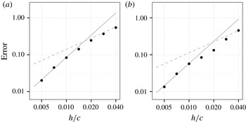
test case. The results converge with second-order accuracy overall and the difference in the solution between an extremely fine reference grid (using 400 points along the chord) and a 200 point-per-chord grid is less than 2 % in lift and drag. The velocity, pressure and vorticity fields for these grids are indistinguishable. This verifies the convergence of these viscous two-dimensional simulations and the 200 points-per-chord grid is used for the remainder of the paper.
Normalized simulation error of the peak values of lift and drag coefficient for the
 ${\it\Xi}=1/4$
,
 $\mathit{Re}=2000$
test case as a function of the grid size
 $h$
: (a) normalized peak error in
 $C_{L}$
; (b) normalized peak error in
 $C_{D}$
. The error is computed relative to the values obtained using a fine
 $c=400h$
reference grid. The solid lines indicate second-order convergence with
 $h$
and the dashed lines indicate first-order convergence.

5. Results and discussion
In § 5.1, we present velocity-field measurements from two test cases (
 ${\it\Xi}=1/4$
and
 $1/2$
) using data from PIV at
 $\mathit{Re}=22\,000$
and BDIM simulations at
 $\mathit{Re}=2000$
. In § 5.2, we present results from force measurements and compare them to the low-order analytic model. First, we compare instantaneous forces between
 $\mathit{Re}$
at high
 ${\it\Xi}$
and discuss differences in view of observed flow topology. Next, we compare the model to results from a large range of
 ${\it\Xi}$
. Finally, in § 5.3 we present the time-averaged lift and drag generated during the manoeuvre with applications to functional tradeoffs in landing birds.
5.1. Velocity-field results
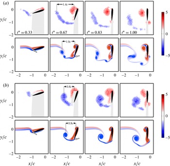
Figure 6 shows vorticity fields arising from the perching manoeuvre, derived from PIV at
 $\mathit{Re}=22\,000$
and simulations at
 $\mathit{Re}=2000$
. For each
 $\mathit{Re}$
, key time steps from
 ${\it\Xi}=1/4$
and
 $1/2$
are shown. These particular cases demonstrate key changes to flow topology as
 ${\it\Xi}$
and
 $\mathit{Re}$
are varied. In all cases presented in figure 6, positive boundary-layer vorticity separates at the leading edge and rolls up into an LEV. Negative vorticity sheds predominantly from the trailing edge. Between
 $t^{\ast }=0.33$
and 0.83, the trailing edge wake appears as a streak of vorticity, connecting with the aerofoil at nearly right angles to the chord. At
 $t^{\ast }=1$
, a stopping vortex forms at the trailing edge.
PIV measurements (upper row,
 $\mathit{Re}=22\,000$
) and simulations (lower row,
 $\mathit{Re}=2000$
) of vorticity fields at (a)
 ${\it\Xi}=1/4$
and (b)
 ${\it\Xi}=1/2$
. Black dotted lines represent the approximate
 $x$
position of the centre of mass of the starting vortex and LEV. In the higher-
 $\mathit{Re}~{\it\Xi}=1/4$
case, the starting vortex trails behind the LEV by a distance of
 $x/c=1.4$
at
 $t^{\ast }=0.67$
, whereas the starting vortex trails less than
 $x/c=1.0$
behind the LEV in the other cases. The white arrows, shown at
 $\mathit{Re}=2000$
, point to a stagnation streamline that connects with the aerofoil near the trailing edge. At
 $t^{\ast }=0.33$
, the stagnation streamline does not lie at the trailing edge. By
 $t^{\ast }=0.67$
, the stagnation streamline has moved to the aerofoil tip. The reference frame translates such that the origin is fixed at the pivot point. The aerofoil is translating in the positive
 $x$
direction. Grey-shaded areas in PIV plots denote regions that have been masked due to shadowing effects or visual obstruction. Vorticity is non-dimensionalized by
 ${\it\omega}^{\ast }={\it\omega}c/U_{0}$
.

Overall the comparison between the high-
 $\mathit{Re}$
experiments and low-
 $\mathit{Re}$
two-dimensional simulations is good, with the same magnitudes of vorticity and coherent structures in the wake. However, some of the differences are worth discussion. In figure 6, the approximate distance between the centre of mass of the LEV and starting vortex are labelled. The LEV remains close to the pivot axis and convects along with the aerofoil. For
 ${\it\Xi}=1/4$
and
 $\mathit{Re}=22\,000$
, the starting vortex is approximately 1.4 chord lengths behind the pivot axis by
 $t^{\ast }=0.67$
. In contrast, at lower
 $\mathit{Re}$
the trailing-edge wake is only
 ${\sim}1$
chord length from the pivot axis at the same
 ${\it\Xi}$
and time. The length of the wake is strongly influenced by the positive
 $x$
velocity of the starting vortex induced by the LEV and other wake vortices. For a given strength, a pair of diffuse vortices induce weaker velocities on one another (Pierrehumbert Reference Pierrehumbert1980; Saffman & Szeto Reference Saffman and Szeto1980). Figure 6 shows that the higher-
 $\mathit{Re}$
wake vortices and LEV are more diffuse due to turbulent transition and vortex breakdown. Therefore, the difference in wake length is explained by turbulent diffusion of vorticity in the three-dimensional higher-
 $\mathit{Re}$
cases, not present in the two-dimensional lower-
 $\mathit{Re}$
simulations.
The simulations also clarify some elements of the flow that are obscured in the PIV. A stagnation streamline is observed in the lower-
 $\mathit{Re}$
cases as the white region between anticlockwise (red) and clockwise (blue) vorticity near the trailing edge, and is marked with a white arrow at
 $t^{\ast }=0.33$
and 0.67. At
 $t^{\ast }=0.33$
, this stagnation streamline does not lie at the trailing edge, therefore violating the steady Kutta condition. As discussed by McCroskey (Reference McCroskey1982), the Kutta condition can break down in highly unsteady manoeuvres, and abrupt streamline curvature can be present in the trailing-edge region. We find that the Kutta condition appears to be established by
 $t^{\ast }=0.67$
. This is consistent with the results of Pitt Ford & Babinsky (Reference Pitt Ford and Babinsky2013), who found that the Kutta condition is violated early in an impulsive manoeuvre due to the presence of the starting vortex, but is established as distance from the starting vortex increases.
5.2. Force history
The forces on the aerofoil from the
 $\mathit{Re}=2000$
simulations and
 $\mathit{Re}=22\,000$
experiments for shape change numbers of
 $1/8$
,
 $1/4$
and
 $1/2$
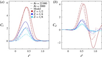
are shown in figure 7 along with the model predictions from (2.18). In all cases, general trends predicted by the analytic model are observed: a single lift peak appears close to
 $t^{\ast }=0.4$
, a drag peak appears close to
 $t^{\ast }=0.5$
, a thrust peak appears late in the manoeuvre, and the magnitudes of all peaks increase with
 ${\it\Xi}$
.
A comparison between force results from experiments at
 $\mathit{Re}=22\,000$
(solid lines), simulations at
 $\mathit{Re}=2000$
(dotted lines) and model predictions (dot-dashed lines) for
 $1/8\leqslant {\it\Xi}\leqslant 1/2$
. The magnitudes and timing of peaks in drag are similar between
 $\mathit{Re}$
cases. The timing of peak lift is similar as well. However, magnitudes of lift are similar only in the
 ${\it\Xi}=1/2$
case. Model predictions are in close agreement with low-
 $\mathit{Re}$
force histories.

Overall, the model agrees with lower-
 $\mathit{Re}$
lift at all
 ${\it\Xi}$
, suggesting that added-mass forces combined with boundary-layer separation at the leading and trailing edges are the dominant mechanisms of lift generation in lower-
 $\mathit{Re}$
cases. In the higher-
 $\mathit{Re}$
cases, however, vortex convection appears to be an important lift-generating mechanism. The vorticity fields shown in figure 6 indicate that streamwise vortex convection is greater at
 $\mathit{Re}=22\,000$
than at
 $\mathit{Re}=2000$
for
 ${\it\Xi}=1/4$
, and the force measurements support this by showing increased lift forces on the aerofoil for
 ${\it\Xi}\leqslant 1/4$
relative to the simulations and the model. Again, the differences in vortex convection between
 $\mathit{Re}$
cases are attributed to turbulent diffusion at higher
 $\mathit{Re}$
not present in the simulation, resulting in convective force that was neglected in the analytic force model.
Drag histories compare well between the model, simulations and experiment, particularly in the large drag peak for
 $t^{\ast }<0.75$
when added-mass and boundary-layer separation are the dominant mechanism of force generation. From
 $0.75<t^{\ast }<1$
, the measurements and simulations demonstrate the parasitic thrust forces predicted by the added-mass model. The magnitude of the thrust measured for
 ${\it\Xi}=1/2$
at higher-
 $\mathit{Re}$
is larger than that predicted by the combined model, but in line with the thrust predicted by the added-mass estimate in (2.3). This indicates that the model overpredicts the vortex drag late in the manoeuvre, probably due to interaction effects between the LEV and trailing-edge wake as the aerofoil comes to a stop.
Figure 7 shows that the accuracy of the model in lift generally increases as
 ${\it\Xi}$
increases for higher
 $\mathit{Re}$
. In § 2.4, we proposed that the model would also become more accurate in the quasi-steady limit because of the von Kármán vortex street, which drives the mean convective force to zero. To assess agreement as
 ${\it\Xi}\rightarrow 0$
, we performed force measurements at
 $\mathit{Re}=22\,000$
with shape change numbers varying from
 $1/8$
to 0 (figure 8). As
 ${\it\Xi}$
is reduced, measured forces approach quasi-steady values at
 ${\it\Xi}=0$
. In the quasi-steady case, note that increased ‘time’ in figure 8 corresponds to increased angle of attack via (2.6), and the mean forces are shown scaled as in (3.1).
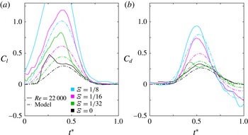
Lift and drag coefficients in non-dimensionalized time, plotted for varying
 ${\it\Xi}$
. The magnitudes of forces increase with
 ${\it\Xi}$
. At lower
 ${\it\Xi}$
, results approach quasi-steady predictions (solid black line). The model is overlaid as a dot-dashed line. Experiment agrees with the model best at low shape change numbers. The
 ${\it\Xi}=0$
case displays a peak lift at pre-stall angles of attack.

A continuation of the trends in figure 7 is observed in figure 8: single peaks in lift, drag and thrust are observed, and the magnitudes of these force peaks continue to decrease as
 ${\it\Xi}$
decreases. As proposed, the model predicts the quasi-steady measurements well overall as long as the angle of attack is sufficiently large to induce shedding from the leading and trailing edges. The flow remains attached along the suction side of this NACA0012 aerofoil section below
 ${\it\alpha}\sim 10^{\circ }\rightarrow t^{\ast }\sim 0.25$
, enhancing lift well above model predictions. At high angles of attack, vortices shed rapidly from the trailing and leading edges, the foil stalls and the lift drops rapidly. Once this rapid shedding begins, the assumptions of the model are satisfied, explaining the better agreement at large
 $t^{\ast }$
. Similarly, in the
 ${\it\Xi}=1/32$
case, lift drops off suddenly after reaching its peak and thereafter is closely predicted by the model. The peak and decay in lift for
 ${\it\Xi}=1/32$
occur at a higher angle of attack than for
 ${\it\Xi}=0$
, which is a manifestation of dynamic stall, a phenomenon in which boundary-layer vorticity remains attached beyond static stall angles of attack in pitching aerofoils (McCroskey Reference McCroskey1982).
5.3. Time-averaged forces
Ultimately, the net forces produced over the course of a perching manoeuvre determine if a flying bird or vehicle can safely land. To come to a complete stop, a bird of mass
 $m$
flying at an initial horizontal speed
 $U_{0}$
must achieve a time-averaged drag of
 $-mU_{0}/T$
and a time-averaged lift equal to its weight. Birds can and do supply some of the force required to land from their legs at touchdown, but most of the momentum change is generated by aerodynamic means (Provini et al.
Reference Provini, Tobalske, Crandell and Abourachid2014).
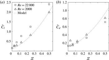
Time-averaged lift and drag for
 $0\leqslant t^{\ast }\leqslant 1$
are plotted against
 ${\it\Xi}$
in figure 9, with lift and drag coefficients derived from
 $\mathit{Re}=2000$
simulations,
 $\mathit{Re}=22\,000$
experiments and model predictions. Minimum time-averaged lift and drag coefficients occur at
 ${\it\Xi}=0$
. Both lift and drag increase as
 ${\it\Xi}$
increases, the former more rapidly than the latter, and appear to be unbounded. The minimum lift requirement is proportional to the constant value
 $mg$
and can be satisfied by increasing
 ${\it\Xi}$
. The minimum drag requirement for a full stop is proportional to
 ${\it\Xi}$
, but since time-averaged drag is predicted to grow as
 ${\it\Xi}^{2}$
, this drag criterion can always be met at high
 ${\it\Xi}$
. This suggests that a bird can simply increase its pitch rate to meet the minimum criteria of a perching manoeuvre, though the costs of fast pitch rates include large torque requirements and high instantaneous loads on the wing.
Time-averaged lift (
 $\bar{C}_{l}$
) and drag (
 $\bar{C}_{d}$
) are always positive and increase with
 ${\it\Xi}$
. Time-averaged lift is greater than drag at higher shape change numbers due to added-mass forces that contribute to lift but detract from drag (figure 2). Time-averaged lift is greater at
 $\mathit{Re}=22\,000$
, compared to
 $\mathit{Re}=2000$
results and model predictions, due to lift generation from vortex convection present in the higher-
 $\mathit{Re}$
cases.

The model predictions are in close agreement with
 $\mathit{Re}=2000$
time-averaged lift. At
 $\mathit{Re}=22\,000$
, the model is in best agreement with time-averaged lift at
 ${\it\Xi}=0$
and
 $1/2$
. The maximum error in the predicted lift force occurs at intermediate
 ${\it\Xi}$
and high
 $\mathit{Re}$
, owing to neglect of the additional lift mechanism of vortex convection. Model predictions also agree with lower-
 $\mathit{Re}$
time-averaged drag and are slightly lower than higher-
 $\mathit{Re}$
results at low
 ${\it\Xi}$
. The large thrust late in the
 ${\it\Xi}=1/2$
experiment reduces the accuracy of the average for that case.
The model predicts that time-averaged lift is much higher than drag at larger
 ${\it\Xi}$
. This is due to added-mass forces that contribute to lift but detract from drag (figure 2). The large differences in integrated lift and drag are amplified by increasing
 $\mathit{Re}$
to 22 000, primarily due to lift generation from vortex convection. A landing bird may thus generate greater time-averaged lift than drag during a pitch-up manoeuvre. This may help explain why the eagle observed by Carruthers et al. (Reference Carruthers, Thomas and Taylor2007) would consistently approach its perch from below, and exhibited a rapid increase in altitude during its pitch-up phase. As the authors of that study suggested, this may be a means to aid deceleration by transferring kinetic energy to potential energy. However, it may also be that the pitching manoeuvre necessary to generate the required drag produces so much excess lift that an altitude correction is needed to avoid overshooting the perch.
6. Summary and conclusions
In this study we investigate how high lift and drag can be generated through a controlled pitch-up manoeuvre in the context of bird perching. As a simple perching model, we study the aerodynamics of an aerofoil that simultaneously decelerates and pitches to a high angle of attack. The pitch rate and deceleration is parametrized by the shape change number,
 ${\it\Xi}$
, a ratio between the speed of frontal area expansion and initial translational speed. We investigate differences in forces and vorticity fields as shape change number is varied from 0 to
 $1/2$
, using force measurements and PIV at
 $\mathit{Re}=22\,000$
and simulations using the BDIM at
 $\mathit{Re}=2000$
. A simple analytic model that includes forces from added-mass effects and boundary-layer separation at the leading and trailing edges is derived and compared to the measurements.
The simulations and PIV measurements for
 ${\it\Xi}=1/4$
and
 ${\it\Xi}=1/2$
reveal that the wake of the perching aerofoil is dominated by a large leading-edge vortex, which remains close to the foil, and the trailing-edge vorticity, which forms a vortex shear layer that rolls up due to Kelvin–Helmholtz instability. The distance between the leading- and trailing-edge structures is found to be greater than the chord length
 $c$
in the
 $\mathit{Re}=22\,000$
and
 ${\it\Xi}=1/4$
case, indicating that vortex convection, neglected in the analytic model, is present in this case. The trailing-edge separation point was found to be located on the suction side of the foil initially, only moving to the aerofoil tip halfway through the manoeuvre, in agreement with previous experiments.
Both experiments and simulations demonstrated that the lift and drag forces increase super-linearly with
 ${\it\Xi}$
, achieving peak values of
 $C_{l}=5.3$
and
 $C_{d}=4.0$
at
 ${\it\Xi}=1/2$
, which are more than an order of magnitude larger than their steady-state peak values. The aerofoil is found to experience parasitic thrust at the end of the manoeuvre, but the average drag on the aerofoil is always positive and increases with
 ${\it\Xi}$
.
Analogous to previous rapid area change studies, we find that added-mass energy in the perching problem is transferred from the immersed body to the fluid as the frontal area and added mass increases, producing large lift and small drag. This energy is then recovered by the aerofoil late in the manoeuvre in the form of a parasitic thrust, which would be counterproductive to a decelerating manoeuvre. However, a simple model of the vortex force developed in this work predicts that the generation of circulation at the leading and trailing edges dissipates enough energy into the wake to nearly overwhelm this parasitic thrust. We find that the analytic model agrees best with force histories at lower
 $\mathit{Re}$
, and with higher-
 $\mathit{Re}$
cases in the limits of quasi-steady and near-impulsive rotation. In particular, the effects of vortex convection were found to be negligible after stall in near steady-state manoeuvres and were overwhelmed by the production of vorticity in rapid manoeuvres. As these forces can be difficult to estimate in transient flows, the simple kinematic model developed in this work is of great utility.
The large forces observed suggest that pitching rates can be tuned to meet the demanding lift and drag requirements of perching manoeuvres. Rapid pitch-up may therefore be a means by which a landing bird can maintain lift while quickly braking to a controlled stop and could be effectively applied in manoeuvrable MAVs in the near future.
Acknowledgements
The authors wish to thank the Natural Sciences and Engineering Research Council of Canada and Alberta Innovates Technology Futures for financial support.