I. INTRODUCTION
Recently, the development of wireless communications at 60 GHz has been very significant with the demonstration of fully integrated transceiver systems achieving data rates of several Gbps. Some applications with a communication range of ten meters or more require the design of antenna systems with a high gain and electronic beam steering. Several groups have demonstrated 60-GHz phased-array antennas with gain levels up to 15–17 dBi integrated on ceramic or multilayer organic substrates [Reference Liu, Akkermans, Chen and Floyd1, Reference Cohen, Ruberto, Cohen, Degani, Ravid and Ritter2]. Electronically-reconfigurable phased-array antennas exhibit real-time highly-flexible beam-forming and beam-steering capabilities, but they are complex to design and fabricate, costly, and exhibit an excessive DC power consumption for many applications. Hence, the radiofrequency (RF) losses experienced in phase-shifters, transmission lines, and antennas at millimeter-wave frequencies make phased-array antennas hardly scalable to high-directivity levels. For this reason, quasi-optically-fed antennas have gained a lot of attention for applications requiring high-directivity beams, such as radars and point-to-point communications.
Reconfigurable reflectarray antennas have been widely investigated with different reconfiguration technologies, such as varactor diodes, PIN diodes, ferroelectric tunable capacitors, liquid-crystal materials, RF-microelectromechanical systems (MEMS) devices, etc. However, few demonstrations were performed above 30–40 GHz due to the lack of low-loss active devices at millimeter-wave frequencies and the lack of a reliable technology to fabricate such devices distributed across a large area. In [Reference Kamoda, Iwasaki, Tsumochi, Kuki and Hashimoto3], a 60-GHz reflectarray based on a single-bit PIN-diode digital phase shifter demonstrated a gain of about 42 dBi and an aperture efficiency of about 9.5%. In [Reference Moessinger, Dieter, Menzel, Mueller and Jakoby4], a 16 × 16-element reflectarray based on liquid-crystal tunable materials is demonstrated at 77 GHz and achieved up to 25° of beam-steering in a single plane.
Transmitarray antennas, or discrete lenses, are dual structures of reflectarrays operating in transmission mode. Less work has been done in this domain and electronically-reconfigurable transmit-arrays have been demonstrated only up to Ka-band [Reference Clemente, Dussopt, Sauleau, Potier and Pouliguen5, Reference Cheng, Lakshminarayanan and Abbaspour-Tamijani6]. In order to reduce the complexity, cost, and DC power consumption of large reconfigurable transmit-arrays, passive transmit-arrays associated with in-package integrated focal sources may provide a competitive alternative with reduced reconfigurability but similar gain level [Reference Dussopt, Zevallos Luna and Siligaris7]. Passive transmit-arrays are fabricated in low-cost printed-circuit board (PCB) technology and have been demonstrated up to the V-band with large transmission bandwidths of 10–20% and antenna efficiencies higher than 50% (including transmission and spill-over losses) [Reference Kaouach, Dussopt, Lantéri, Koleck and Sauleau8, Reference Phillion and Okoniewski9]. A similar concept is presented in [Reference Artemenko, Maltsev, Mozharovskiy, Sevastyanov, Ssorin and Maslennikov10] where a switched-beam integrated lens antenna is demonstrated at V-band, this design was based on a quartz extended hemispherical lens, four switched aperture-coupled microstrip antennas, and Single Pole Double-Throw (SPDT) monolithic microwave integrated circuit (MMIC) switches.
This work builds upon our previous work on 60-GHz passive transmit-arrays and 60-GHz antennas integrated on silicon to propose a multi-beam antenna associating a passive transmit-array and a focal source array integrated on silicon (Fig. 1). The objective is to achieve a good compromise between the gain, the aperture size, the cost (PCB, small-size integrated focal source array), and the beam steering capabilities (reduced steering range as compared to a conventional phased array). As compared to phased-array antennas, an expected benefit is a significant simplification of the transceiver circuit since a single transmit/receive chain is needed and the beam selection can be made by using a Single-Pole N-Throw (SPNT) switching circuit (not studied in this work) between the transceiver and the focal source array.
Schematic of the transmit-array illuminated by a focal source array.

In this work, the design of the transmit-array unit-cell previously presented in [Reference Kaouach, Dussopt, Lantéri, Koleck and Sauleau8] has been updated in order to provide a 3-bit phase quantization (as compared to 2 bits in [Reference Kaouach, Dussopt, Lantéri, Koleck and Sauleau8]) and the transmit-array was optimized for a focal array composed of five identical integrated antennas previously developed in [Reference Dussopt11]. The complete simulated and measured performances are presented and compared, showing a very good agreement. Section II details the design of the antenna prototype; the focal source array, the transmit-array unit cell, and the 10 × 10-elements transmit-array are presented in Sections II(A)–II(C), respectively. Section III reports the simulated and the experimental performances in gain and radiation patterns. Finally, the results and demonstrated performances are summarized in Section IV.
II. ANTENNA DESIGN AND OPTIMIZATION
A) Focal source array
The focal source array consists of five folded-dipole antennas integrated on high-resistivity (HR) silicon [Reference Dussopt11]. The previously reported performances in [Reference Dussopt11] showed a gain of up to 4–7.9 dBi in the broadside direction for a single antenna element and a reflection coefficient below −14 dB across the 57–66 GHz band. The reflection coefficient is not significantly changed in the presence of the transmit-array because it is located at about 10 mm (2 wavelengths at 60 GHz) from the focal sources (Section II(C)), the unit-cells are well matched (Section II(B)), and a very minor part of the power reflected by the transmit-array returns to the focal source. The array is composed of five individual antenna chips (5 × 15 mm2) assembled side-by-side with a center-to-center distance of 3 mm (0.6 wavelength at 60 GHz). Note that the array could be more compact if it was realized on a single chip with an inter-element spacing of 2.5 mm as in [Reference Dussopt11]. The focal source array was placed on a circular metal plate covered with an absorbent material to limit multiple reflections between this plate and the transmit-array (Fig 2(b)). Three dielectric struts (Delrin, Ø = 6 mm) are used to hold the transmit-array above the focal source array, the struts length defines the focal distance (F).
Top view (a) and photograph (b) of the focal source array composed of five folded dipole antennas integrated on silicon.
B) Transmit-array unit-cell
The transmit-array design is similar to the one previously reported in [Reference Kaouach, Dussopt, Lantéri, Koleck and Sauleau8]. It is made of three metal layers and two low-loss dielectric substrates Rogers RO3003 (ε r = 3, tanδ = 0.0013, and h 1 = 254 µm) and Rogers RT/Duroid 6002 (ε r = 2.94, tanδ = 0.0012, and h 2 = 127 µm) assembled by using an adhesive layer Rogers 4450 (ε r = 3.52, tanδ = 0.004, and h 3 = 100 µm) (Fig. 3(a)); the substrate properties are given here at 10 GHz and supposed to be similar at 60 GHz. The array unit cell is composed of two identical patch antennas (L p = 1.22 mm, W p = 1.22 mm) printed on the opposite sides of the substrates stack and interconnected by a metallic via (Ø = 100 µm) through the ground plane (Fig. 3(a)). Eight different unit-cells were designed with different orientations (α = 0°, 45°, 90°, 135°, 180°, 215°, 270°, or 315°) of the top patch (Fig. 3(b)) in order to generate a circularly-polarized radiation beam thanks to a sequential rotation of the top patch antennas. These phase-shifting unit-cells implement a 3-bit phase quantization [Reference Kaouach, Dussopt, Lantéri, Koleck and Sauleau8]. After optimization, they exhibit under a normal incidence a resonance at 60.3 GHz, a reflection coefficient lower than −10 dB across the 59.2–61.6 GHz band, and insertion losses of about 0.4 dB at 60 GHz. A maximum offset of 1 GHz is obtained in the resonance frequency for 50° of incidence angle (Fig. 3(c)).
The transmit-array unit-cell. Cross-section (a), top view, (b) and S-parameters of the unit cell illuminated by a plane wave for several incidence angles (c).
C) Transmit-array
The design of the transmit-array combines the electromagnetic simulations of the focal source and the unit cells with an analytical model of the full antenna according to the procedure shown in [Reference Kaouach, Dussopt, Lantéri, Koleck and Sauleau8]. The transmit-array is composed of 10 × 10 cells (D = 25 mm). The distribution of the unit-cells was optimized for a maximum gain in the broadside direction (OZ axis) when the central element of the focal source array is selected (port 1 in Fig. 2(a)). Figure 4(a) presents the gain and the directivity as a function of the focal ratio (thin lines in Fig. 4(a)) when the distribution of the unit-cells is optimized for each focal ratio. This plot shows a maximum theoretical gain of 14.2 dBi and a directivity of 21 dBi for a focal ratio F/D = 0.48 (F = 12 mm). A significant difference of 6.9 dB between the gain and the directivity is observed and corresponds to an efficiency of 20.5%. This is explained by the spill-over losses (−2.5 dB), the focal source efficiency (61%, 2.2 dB), the unit-cells insertion losses (0.5 dB), and the reflection losses. The reflection losses are not directly calculated by our simulation tool but are estimated to be about 1.7 dB to fulfill this power budget; such losses may result from the effect of the incidence angle between the focal source and the unit-cells, and the cross-polarization level of the focal source.
(a) Gain and directivity as a function of the focal ratio at 60 GHz; the thin curves correspond to the values obtained if the unit-cell distribution is optimized for each F/D value, while the thick curves are obtained for the unit-cell distribution optimized for F/D = 0.48. (b) Photograph of the fabricated prototype.
Then, the optimal cell distribution (Fig. 4(b)) is used to study the sensitivity of the array to the focal distance (thick lines in Fig. 4(a)). An F/D ratio in the range of 0.38–0.6 (blue zone) leads to a gain value within 1 dB below the maximum, indicating a rather low sensitivity of the array performances to the focal source position in this range. Therefore, a focal distance of F/D = 0.4 (F = 10 mm or 2 wavelength) only was chosen in order to minimize the total height of the antenna and better satisfy the integration constraints in a large set of smart devices, e.g. wireless displays, projectors, desktop computers, etc.
It is worth noting that generating a circularly-polarized beam using a sequential rotation of linearly-polarized unit-cells results in about 3 dB of directivity reduction; therefore, a future design based on the circularly-polarized unit-cells would lead to significantly higher gain and directivity values for the same aperture area.
III. RADIATION PERFORMANCES
A) Measurement setup
The radiation measurements are performed in an anechoic chamber by using a test setup specifically designed for the probe-fed integrated antennas. The Antenna-under-Test (AUT) is placed on a rotating table (azimuth rotation over ±180°) including a V-band millimeter-wave converter, a micropositioner, and a custom RF probe (Fig. 5). The test antenna (linear polarization 20-dBi horn) is at the end of an arm rotating in elevation over ±90° at 403 mm from the AUT and is connected through rigid waveguides to another millimeter-wave converter.
Measurement setup installed in an anechoic chamber (d = 403 mm) (a); photograph of the AUT (b).
The measurements are performed with a vector network analyzer connected to both the millimeter-wave converters through flexible 3.5-mm phase-stable coaxial cables; this is especially important since both the magnitude and the phase of the transmission coefficient need to be measured accurately in order to extract the circularly-polarized gain radiation patterns.
The measurements are performed by placing the RF probe successively on the input pads of each element of the focal source array; this requires a custom RF probe with a coaxial extension [Reference Fu, Dussopt, Vuong and Ndagijimana12]. All of the measurements are fully automated with a computer control of the two rotation axes and the vector network analyzer. The experimental radiation patterns presented in this paper are measured with an angular and a frequency resolution of 1° and 0.1 GHz respectively.
B) Simulated and experimental results
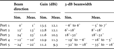
The simulated and the measured radiation patterns are plotted in Fig. 6 for F/D = 0.4 (F = 10 mm). The measured and the simulated broadside gains in the ZX-plane are 12 and 13.4 dBi, respectively. The measured radiation patterns exhibit a right-hand circularly-polarized (RHCP) broadside beam with a cross-polarization level of −9.6 dB. The 3-dB beamwidth is 12° and 10° in the ZX-plane and ZY-plane, respectively. The five beam directions are 1°, 13°, 23°, −10°, and −22° for each focal source 1, 2, 3, 4, and 5 respectively. In each case, the main beam and the sidelobe levels are comparable in the simulation and the measurements. Some discrepancies in the cross-polarization (left-hand circularly-polarized, LHCP) levels are observed. This is explained by several factors as the multiple uncertainties in the prototype assembly, the measurement-setup, or the simulation model: focal distance, planarity of the transmit-array, alignment between the transmit-array and the focal sources, accuracy of the focal sources simulated radiation patterns, residual spill-over radiation and scattering on the dielectric struts, and array edges or other elements from the setup. It is important to note that millimeter-wave communication applications envisioned for such antennas do not impose any requirement on the sidelobe levels and the systems performances are mostly dependent on the absolute gain and the width of the main beam.
Simulated (dashed lines) and measured (continuous lines) radiation patterns of the transmit-array at 60 GHz in the ZX-plane for each focal source 1, 2, 3, 4, and 5 respectively (F = 10 mm).
The gain frequency response of the transmit-array (Fig. 6(a)) by using the central element of the focal source array shows a good agreement with the simulation, although the experimental gain is slightly higher than the simulation above 62 GHz. The measured gain is maximal (15.7 dBi) at 62.8 GHz. The measured 3-dB gain bandwidth is 12.2 GHz in the range 57.8–70 GHz, which is suitable to work in the 57–66 GHz ISM band. The main performances are summarized in Table 1.
Simulated and measured performances of the switched beam transmit-array at 60 GHz in the ZX-plane.
IV. CONCLUSION
A V-band switched-beam transmit-array antenna combining low-cost printed technology and silicon-integrated antennas is presented. The transmit-array is fed through a focal source array of five folded dipole antennas integrated on HR silicon. The array provides five separate beams in circular polarization covering a total angular sector of 64° × 10°. The maximum gain is 12.1 dBi at 60 GHz and 15.7 dBi at 62.8 GHz. These good performances across the 57–66 GHz ISM band seem suitable for many short-range and low-cost millimeter-wave communication and radar applications.
José A. Zevallos Luna was born in Lima, Peru in 1985. He received a B.Sc. degree in electrical engineering from the Universidad Nacional de Ingenieria, Lima, Peru, in 2006, the M.S. degrees in microelectronic and telecommunications engineering from the University of Provence Aix-Marseille I, France, in 2011, and is currently pursuing a Ph.D. degree in optic and radiofrequency at the University of Grenoble, France. Since February 2011, he has been a Research Assistant with CEA-LETI, Grenoble, France. His research interests include millimeter-wave integrated antennas and antenna arrays.
Laurent Dussopt received the M.S. and the Agrégation degrees in electrical engineering from the Ecole Normale Supérieure de Cachan, France, in 1994 and 1995, a Ph.D. degree in electrical engineering from the University of Nice-Sophia Antipolis, France, in 2000, and the “Habilitation à Diriger des Recherches” degree from the University Joseph Fourier, Grenoble, France, in 2008. From September 2000 to October 2002, he was a Research Fellow with the University of Michigan at Ann Arbor. Since 2003, he has been a Research Engineer at CEA-LETI, Grenoble, France. His research interests include reconfigurable antennas, millimeter-wave integrated antennas and antenna arrays, and RF-MEMS devices and systems.