NOMENCLATURE
- eVTOL
electric VTOL, usually taken to mean using batteries as the energy source
- ṁ
mass flow
- V
Velocity
- VTOL
Vertical Take-Off and Landing
- V/STOL
Vertical or Short Take-Off and Landing
- β
Yaw angle
1.0 INTRODUCTION
In light of the massive renewed interest in personal, light or small aircraft able to perform Vertical Take-Off and Landing (VTOL), this paper reviews some aspects of the basic physics of this form of flight, mostly using examples from the author’s past experience in the development of military jet-lift V/STOL aircraft. The paper also reviews some of the recent technology enhancements that are fuelling the newly proposed projects.The paper is based on the 2018 Lanchester Lecture with some re-ordering and additional explanation to make it suitable as a written paper, rather than a presentation.
2.0 WHAT IS THE VTOL DREAM?
Having posed the question in the title, the actual dream that is referred to needs to be defined. There is a multiplicity of potential missions that could be served by a VTOL aircraft. These include urban taxis or suburban commuter missions, so-called last mile delivery, and inter-city transit. The key feature that unites these missions is the desire to have flexibility of where to take-off and land and, particularly, in not being tied to very large fixed facilities with, in the context of an urban setting, an enormously long runway.
Of course, helicopters can currently perform the urban taxi or commuter mission, but traditional helicopters have significant drawbacks in that they are expensive to operate and noisy. Within the urban environment, safety considerations place limitations on their operation. For an urban air taxi, it is sufficient to travel at automobile speeds: the route will be more direct and there won’t be any traffic jams, so journey times would be much faster. Such speeds are probably within the range of quadcopter-type rotorcraft, which have significantly less-complex rotors than helicopters.
Of course, if there are large numbers of VTOL aircraft in an urban environment, then safety considerations mean there must be a step change in air traffic control. This would most likely need to be an automated system with command and control over individual aircraft within a particular zone. Allowing individuals to pilot their own aircraft and relying on autonomous collision avoidance systems would not enable the density of air traffic that would be needed.
Air transport in the urban environment is probably where most of the current crop of VTOL aircraft are aimed, but for this writer and most of this paper, the mission of interest is really inter-city transit. In order to significantly beat journey times for cars and trains, the VTOL aircraft needs to be able to fly at turboprop-like speeds. This is not achievable by a helicopter, so the VTOL aircraft needs to be able to transition into wing-borne flight for the majority of its flight time, meaning that wing-borne efficiency is more important than powered-lift efficiency.
The majority of the paper concentrates on some of the technical aspects of transitioning VTOL aircraft, using examples from the writer’s past, to help illustrate some of the special difficulties of this class of aircraft.
3.0 FREDERICK LANCHESTER
Frederick Lanchester had a varied career in the formative days of both the aeronautical industry and the automobile industry. Nowadays, he is best remembered by aerodynamicists for his work on aircraft stability, particularly longitudinal stability, through the series of gliders that he flew from his home, and his analysis of their flight behaviour. Reference Reference Jarrett1 has a good summary of Lanchester’s aeronautical work.
Figures 1 and 2 show images of two of his gliders. A feature of these craft, in which all surfaces were fixed, was that they all featured two fins: one ahead of the wing and one close to the tailplane. It appears that Lanchester was constrained by two-dimensional thinking and didn’t intuitively grasp the concept of bank-to-turn. At this stage of his career, his control philosophy was to coordinate rudders on the two fins to perform flat turns. Nowadays, of course, we understand the efficiency of bank-to-turn and the destabilising properties of the fin ahead of the centre of gravity, or anti-fin. However, this feature of the anti-fin provides the link between Lanchester and VTOL aircraft, which is part of the requirement of the named lecture!
Image of Lanchester glider.

Drawing of Lanchester glider.

4.0 DISC LOADING
The absolute most important parameter regarding the efficiency of VTOL aircraft is their disc loading. This is the measure of the aircraft weight and, hence, the approximate vertical thrust divided by the planform area of the lift-generating system i.e. the rotor or the jet nozzles. Disc loading is analogous to the measure of propulsive efficiency in the conventional flight mode. Thus, for a given thrust, the velocity will increase as area decreases. Importantly, the power required to generate a given thrust decreases as area increases.
Figure 3 illustrates the variation of power, expressed as hover lift efficiency, and jet velocity against disc loading. This line takes no account of system losses, so the realised hover lift efficiency will be a bit lower than that shown and will have some scatter in the line. It should be noted that the x-axis is logarithmic. The figure shows roughly where helicopters, tiltrotors and the Lockheed Martin F-35B Lightning sit on the characteristic.
Hover efficiency vs disc loading.

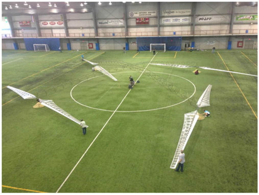
The figure makes the point that for high efficiency in the hover, to lift the greatest weight for a given power, it is important to have a very low disc loading. Extrapolating this to the extreme is the human-powered helicopter developed at the University of Toronto(2), shown in Fig. 4. The total rotor area can be seen to be enormous, while the light-weight structure holding it together is difficult to see. The pilot, otherwise known as the power source, is installed in the centre of the circle.
Disc area required for a human-powered helicopter.

While the hover efficiency of the F-35B with lift fan can be seen to be rather low this is not the issue it may seem to be, as the aircraft requires very high installed power and high jet velocities to perform supersonic flight. The use of the lift fan reduces the disc loading to the levels shown and matches the thrust requirements for both hover and high-speed flight.
In contrast, the P.1216 project, which the author worked on when first starting at BAE and shown in Fig. 5, was the ultimate extrapolation of the simple Harrier concept with a single engine. In order to achieve supersonic flight, the front nozzles had afterburners; however, the efflux from these would have caused too much damage to the rear fuselage; hence, the use of the tail booms. In the VTOL context, the aircraft also needed the afterburners to achieve the required vertical thrust. The disc loading was well to the right of that for the F-35B shown on the graph, and the very hot, high velocity jets would have severely limited the basing flexibility of the aircraft compared with Harrier. The main point of interest for this project now is that the rear nozzle saw the first appearance of the three-bearing swivel nozzle that is now utilised on the F-35B.
P.1216 STOVL project.

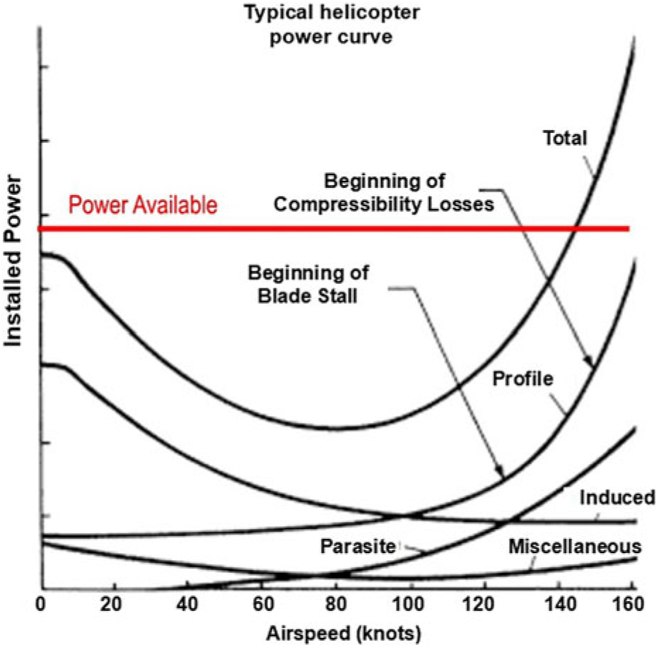
The balance of installed power against speed for a typical helicopter is shown in Fig. 6. The high hover efficiency achieved from a large horizontal plane rotor quickly leads to inefficiencies at relatively low forward speeds due to advancing blade compressibility losses and retreating blade stall. For the case shown, the economic cruise speed is of the order of 80 or 90 kn, which is not significantly different to automotive speeds for inter-city travel.
Required power vs speed for a helicopter.

Tiltrotors transition from rotor-borne lift to wing-borne lift, overcoming the limitation of the helicopter rotor and allowing significantly faster speeds to be achieved. However, the diameter of the rotors is a compromise, being rather too large in aeroplane mode and, thus, very lightly loaded when being used as propellers. The complexity and operational cost of tiltrotors means they don’t meet the criteria of the VTOL dream.
5.0 JET EFFECTS
This section describes some of the aerodynamic phenomena of non-rotorcraft VTOL aircraft, which can be conveniently thought of as jet-lift aircraft, in the hover and during transition between jet-borne and wing-borne flight. These are dealt with in significantly more detail in Ref. Reference Kuhn, Margason and Curtis3.
5.1 Hover lift loss
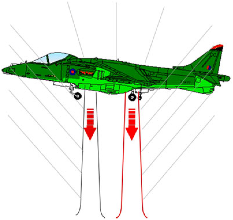
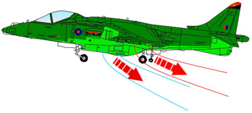
One of the most basic phenomena to be accounted for with VTOL aircraft is that the vertical thrust from the propulsion system causes a secondary effect on the aircraft, creating a form of vertical drag. For a jet-lift aircraft, this is illustrated in Fig. 7 and is due to the process of entrainment into the jets; entrainment being the viscous phenomenon of pulling surrounding air into the jets and, thus, reducing their velocity and increasing their area. The lines on the figure show the approximate angle of streamlines in the entrainment flowfield. The important point to note is that the aircraft is sitting in the flowfield and is experiencing a downward force because of it.
Out of ground effect hover.

For practical configurations, the value of hover lift loss out of ground effect is in the order of 3% of the jet thrust. This varies slightly with wing shape, the placement of the nozzles and their operating condition, but not massively. So, in order to hover, the lift system must produce 1.03 times the aircraft hover weight. In addition, the lift system must have thrust in reserve to arrest a descent and permit control in all three axes, normally in the region of 5% and 2%, respectively. So, a useful rule of thumb is that the aircraft needs 10% more thrust available than its hover weight. Hover lift loss also affects helicopters and tiltrotors from the airframe structure directly in the rotor downwash.
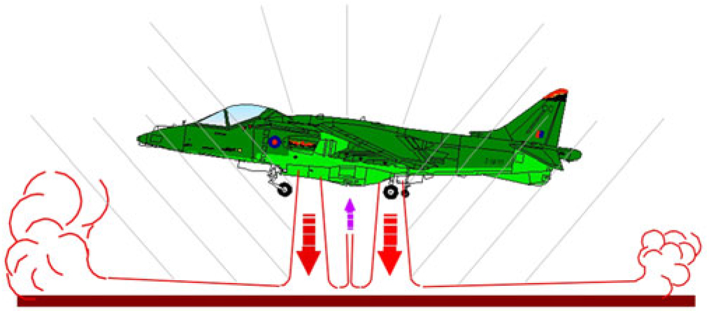
Moving into ground effect, the induced effects become more complex and potentially more severe. When the lift jets reach the ground, they turn and are then referred to as ground jets, as illustrated in Fig. 8. The entrainment field around the airframe becomes much stronger due to the much higher surface area of the jet edges and the proximity of the airframe to the jets. Lift loss values at wheels-on can be as high as 15% of thrust.
In ground effect hover.

However, this can be offset by the presence of fountain flows, which can be seen as the arrow pointing up between the two lift jets in the figure. Fountain flows are created where two or more ground jets meet and are turned upwards. They are generally very unsteady but can be captured and managed by an appropriate structure on the airframe. For the Harrier aircraft, the under fuselage strakes and dam actually give a lift gain at wheels-on, although this very rapidly diminishes with height. The complex flowfields associated with ground effect and their interaction with the airframe can lead to very rapid changes of pitching moment with height.
The image in Fig. 9 shows a flow visualisation experiment for an F-35B jet-blowing model. Water is being injected into the rear jet and is being illuminated by a laser sheet on the aircraft centreline. Water vapour is being entrained into the front jet; hence, this can be seen from a short distance beneath the aircraft rather than from the nozzle exit. The fountain formed between the two jets can be seen rising from the ground. The video from which this still is taken shows the high instability of the fountain.
Fountain flow.

5.2 Transition lift loss
With forward speed, where the aircraft is semi-jet-borne, there are some additional phenomena to be considered. The jet plumes, illustrated in Fig. 10, create a blockage that significantly alters the flowfield around the airframe. This can be thought of as an inviscid effect, to add to the viscous effect of the entrainment.
Flowfield in transition.

The effect of jet placement relative to wings has been studied extensively in the past. Broadly, having a jet near the leading edge reduces the local angle-of-attack, while having a jet near the trailing edge enhances the circulation of the wing, like a jet flap. Large changes of pitching moment can also be experienced.
Figure 11 shows a McDonnell Douglas gas-coupled lift fan concept from the early/mid-1990s, which the author worked on. Because the rear lift nozzles were buried in the centre of the large main wing, rather than at the edge as on Harrier, this had a relatively high lift loss through transition. This was a necessary compromise in order to optimise the up and away performance.
McDonnell Douglas gas-coupled lift fan concept.

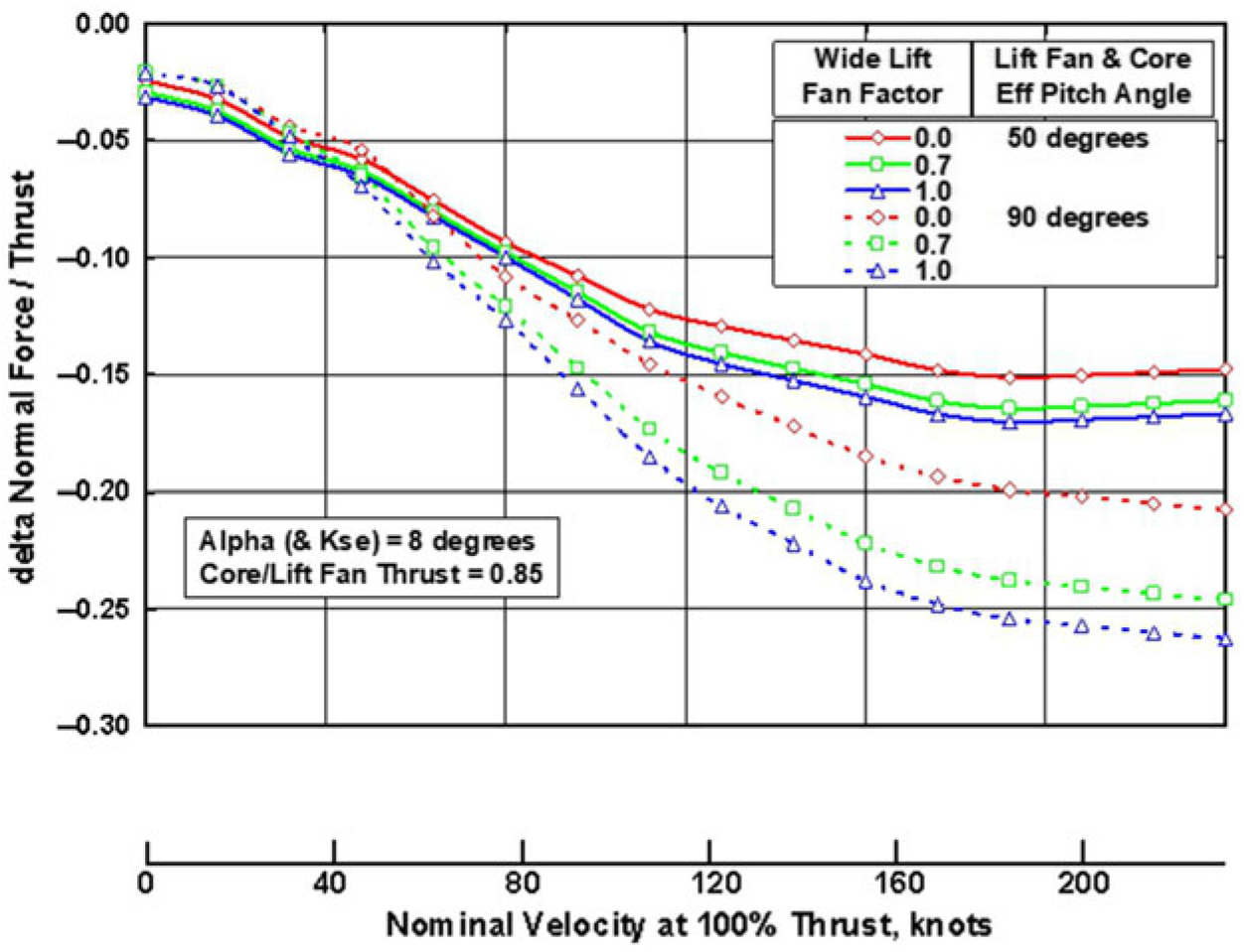
Figure 12 shows wind-tunnel data from this configuration illustrating how lift loss increased through the transition speed range. At higher speeds, the loss of lift can be as much as 15% of the installed thrust for a representative thrust vector angle of 50°. While this might seem excessive, it should be remembered that at these higher speeds the aerodynamic lift is much more powerful as it increases with speed squared, and relatively modest changes in angle-of-attack or flap angle, etc., can offset the lift loss. The intermediate speeds, prior to significant aerodynamic lift, tend to be where margins are at their minimum.
Lift loss through transition speeds for the gas-coupled lift fan concept.

5.3 Intake momentum
Intake momentum force is experienced by all aircraft but becomes a significant factor for jet-lift aircraft during transition. In force and moment accounting, it is assumed that the streamtube of air entering the intake is brought to rest at the plane of the intake. The momentum of this streamtube creates a force opposed to the line of flight; hence, it is often referred to as a drag, although this is strictly speaking not correct. For conventional aircraft, the intakes are generally aligned with the line of flight, reducing any resulting moments. For jet-lift aircraft, the intake can be at extreme angles to the flow direction, up to 90° for lift fans, and the resulting moments very high.
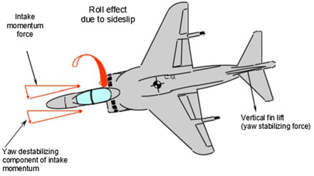
The Harrier aircraft was known for having a roll instability in transition that could overcome the control authority of the aircraft. This was primarily caused by the effect of the intake momentum if yaw was allowed to build up, as illustrated in Fig. 13. With the intake being well ahead of the centre of gravity, it creates a de-stabilising moment in yaw proportional to ṁVsinβ, where ṁ is the mass flow into the intake, V is the aircraft speed and β is the angle of yaw. The cross-coupling effect of the sideslip also creates a rolling moment. At low speed, it was possible for these effects to saturate the available control power and lead to a crash.
Effect of intake momentum on Harrier.

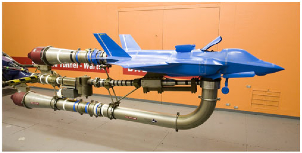
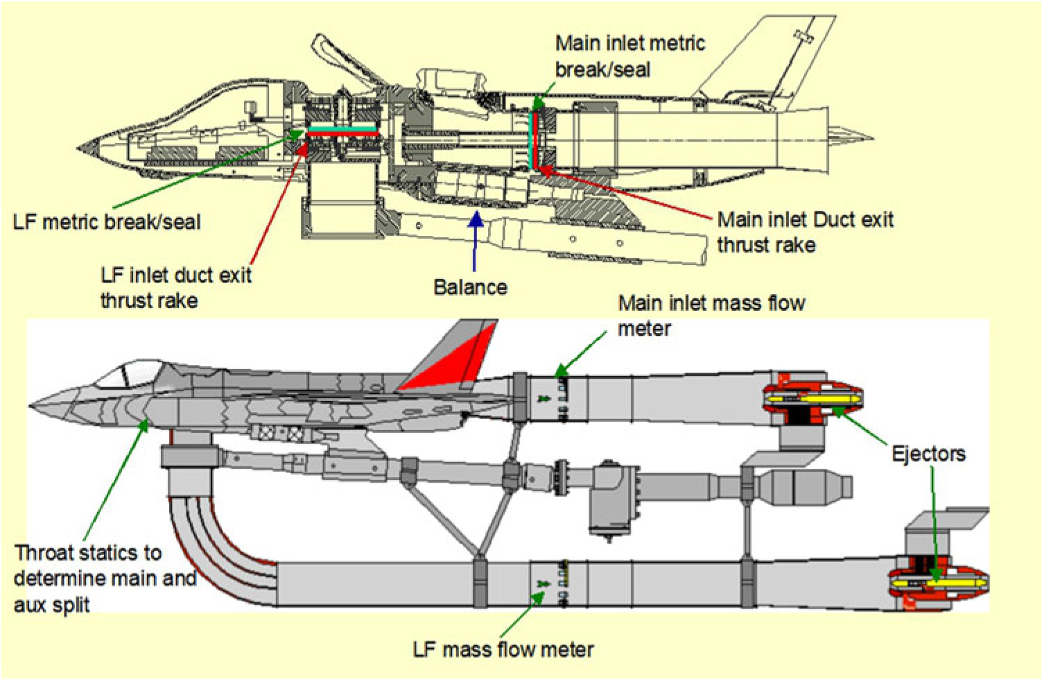
For aircraft with lift fans, the intake momentum-induced moments are potentially much higher than the forward-facing intakes of the Harrier. For the F-35B Lightning, it was felt necessary to thoroughly investigate these effects through the use of a wind-tunnel model, illustrated in Figs. 14 and 15.
Intake momentum forces and moments wind-tunnel model.

Detail of wind-tunnel model.

The F-35B has a main intake, auxiliary intake and lift fan intake, with the total mass flow being about double that of the Pegasus engine in the Harrier. The main induced moment from the lift fan is a nose-up pitch, but at yawed conditions it will also create both yawing and rolling moments.
The wind-tunnel model can be viewed as extremely complex as it was necessary to have both main engine and lift fan systems working at the same time and to isolate the induction systems from the balance measuring the forces on the airframe.
5.4 Control power in transition
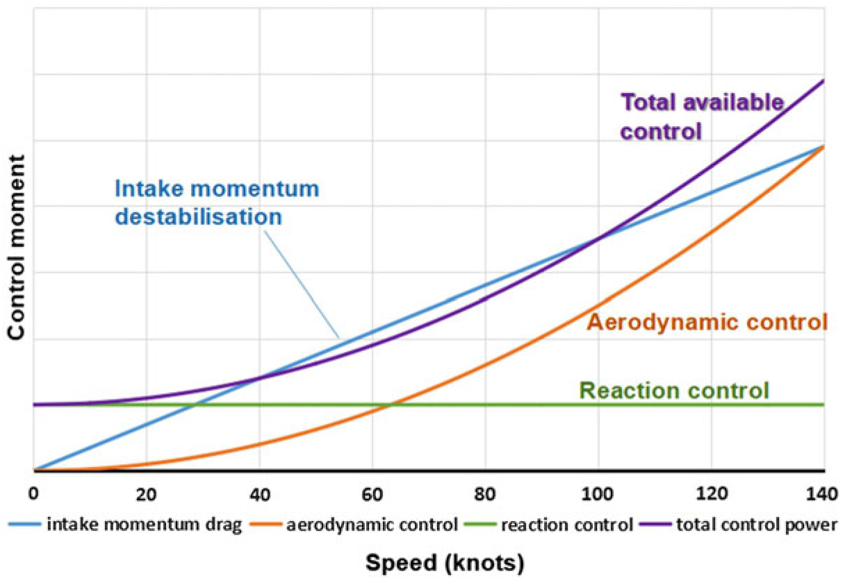
Using the example of the intake momentum induced moments, this section examines the issue of control through the transition corridor. Control in the hover is achieved either with thrust modulation of the main lift jets or through the use of reaction control jets, whereas control (and stability) is achieved through the use of aerodynamic surfaces in conventional flight. During transition, a combination of the two forms of control is needed, as the aerodynamic control effectiveness is dependent on having sufficient speed.
To a first order approximation, ignoring induced effects, the thrust-based control moment is independent of aircraft speed, while the aerodynamic control moment is proportional to the square of speed. As previously stated, the intake momentum-induced moment is proportional to the speed of the aircraft. These effects have been combined in a cartoon illustration in Fig. 16. In this case, it is showing plenty of control power margin in hover and at 140 kn, but a slightly negative margin in the centre of the transition corridor at 70 kn. Clearly, for this case, more work is required to give a positive margin, but it is typical of all VTOL aircraft that transition to wing-borne flight in having a speed band where control is marginal. Overcoming this can have a very detrimental effect on the overall feasibility of a concept.
Control power required vs speed.

6.0 ELECTRIC PROPULSION
Advances in battery and electric motor technology have made the prospect of electric propulsion more attractive and have led to many concepts being examined and put forward. This section very briefly reviews some of those advances.
To date, battery technology at the scale needed for passenger aircraft has been driven largely by the automotive sector. Mass and volumetric efficiency has been improved markedly in recent years, but there is much to be done to match the energy density of kerosene. Lithium Ion batteries have a density of the order of 200Wh/kg, while kerosene has a density of 12,000Wh/kg, a factor of 60 different. As with other types of air vehicles, battery-powered VTOL aircraft will have to land at the same weight as they take-offFootnote 1, which has implications for landing gear design and overall structural mass. It is clear that incremental improvements in battery energy density will not make significant inroads into the superior power density of fossil-based fuels.
However, the story for electric motor technology is much better than for batteries. Power densities for advanced electric motors are in the region of 0.7 kW/kg, compared with around 0.17 kW/kg for legacy reciprocating engines used in light aircraft. It should be noted that large aircraft gas turbines can achieve power densities as high as 2 kW/kg.
Of course, the overall propulsion system mass is a combination of the energy source (battery or liquid fuel), the propulsor motor, distribution systems (cables and power electronics or tanks, pumps and fuel pipes), any cooling systems, etc., so it is not as simple as just comparing battery power density relative to liquid fuel. However, the longer the mission the less likely it is that pure battery power will be sufficient. It is for these reasons that hybrid systems are of interest, utilising a liquid fuel-powered electricity generator.
From the evidence of where battery technology currently is, and is likely to get to in the near term, and from the discussion about disc loading and hover thrust efficiency, the most logical solution for an electric VTOL aircraft is one that has the disc loading of a helicopter or lower.
7.0 PROPELLERS AT INCIDENCE
Another potential issue to be considered for non-helicopter rotorcraft, such as variants of the quadcopter layout, tiltrotor and tiltwing configurations, is the aeromechanical effects of propellers at incidence i.e. where the flow is not at 90° to the plane of the propeller disc. The cyclic loading of aircraft propellers at even very low angles introduces an oscillatory load on the blades that can lead to fatigue issues for highly loaded components.
For quadcopter-type concepts, the flow is at very high angles to the propeller disc that introduces very high oscillatory loading. The complex and expensive to maintain hubs on helicopters are required to cope with these oscillatory loads and the effect they have on stability and control of the aircraft. One of the reasons that simple propellers can be used on quadcopter drones is their light loading and low speed. Upscaling to people-carrying vehicles, while keeping weight sensibly low, will inevitably lead to a much higher loading of these components, which may negate the benefits of simplicity and low cost.
8.0 NOISE
The relative quietness of remote-control drones and the absence of a combustion engine, reciprocating or gas turbine, lead to the easy assumption that electric VTOL aircraft will be quiet. This is by no means a safe assumption to make. Most of the noise from a helicopter is aerodynamically generated, with blade vortex interactions being a major player(Reference Leverton4). While non-helicopter rotorcraft do not generate noise with a tail rotor, they do have more complex vortex interactions.
9.0 VTOL CONCEPTS
There are many VTOL projects currently proposed and under some form of development, with seemingly new ones announced every week. This section looks at a small number that the author has found on the various web sites. It is not intended to hold these up as particularly good or bad examples, but to highlight some of the factors discussed previously and see how they affect these concepts.
9.1 Multicopters
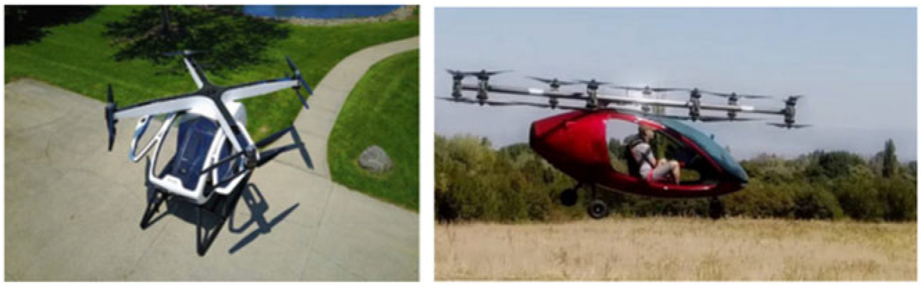
The most numerous examples of VTOL aircraft use variations of the drone-style quadcopter but usually with more than four rotors. Figure 17 shows two such aircraft. One of the things to note with these two aircraft is that the swept area of the rotors is subjectively lower than would be expected for an equivalent helicopter; hence, they are coming down the hover lift efficiency curve. However, as with all aircraft of this configuration, there is no requirement for a power draining tail rotor to counter torque or for the weight of structure to carry the tail rotor; thus, reducing the disc loading and restoring some of the lost hover lift efficiency. The strength of these designs is that they are mechanically simple, but the configuration is inherently low speed.
Quadcopter derivative aircraft.

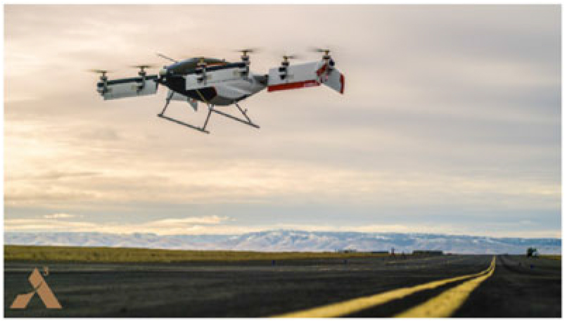
The tiltwing multicopter shown in Fig. 18 has the benefit of transitioning to wing-borne flight and the subsequently large reduction in power needed for cruise. However, the disc loading in hover is limited by the wingspan and the distance between adjacent engines. If the wings are optimised for cruise, this will certainly limit the hover lift efficiency. The relatively high downwash velocities will also increase the noise generated by the aircraft, however quiet the motors.
Tiltwing multicopter.

This configuration would have to be very careful of the interference from the forward wing and propeller wash on the rear wing and propellers in conventional flight, which could reduce efficiency and create aeromechanical effects.
9.2 TriFan 600
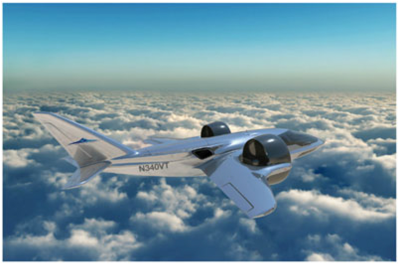
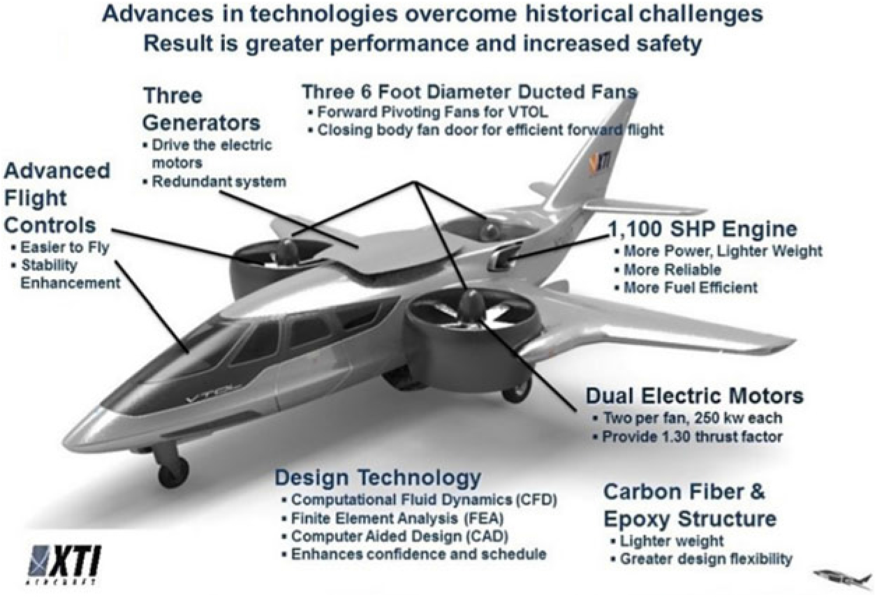
This configuration, illustrated in Figs. 19 and 20, has has considerable data published on it and is designed to meet the inter-city transit mission, with a maximum cruise speed of 550km/h. Early publicity showed a fully battery-powered aircraft but, in more recent times, this has switched to showing a gas turbine generator powering the electric motors. The sums obviously showed that battery technology would not allow them to meet the mission.
TriFan 600 in conventional flight mode.

TriFan 600 publicity.

Using the published data for a VTOL mission, the TriFan 600 has a disc loading of 3000 N/m2, rather higher than the V-22 Osprey at about 1100 N/m2, and a hover lift efficiency of 28.7 N/kW. It is not optimised for the vertical part of the mission! The configuration neatly deals with the problem of having excess thrust in conventional flight by stopping and covering the third fan, meaning the two drive fans are better matched to this phase of flight than tiltrotor propellers are.
In hover mode, if this rear fan is producing the same thrust as the front two, then the centre of gravity looks a little too far aft for the wing, so could potentially be downsized to save weight. Although it should be remembered these are still only artists impressions.
From some of the earlier discussion, it might be expected that the fuselage-mounted fan intake would produce a reasonably high pitch down moment during transition, and that the placement of the fans ahead of the leading edge would lead to high lift loss on the inner wing. Also, there are likely to be some very large trim changes as the fans vector aft and the jet crosses the wing. For these reasons, by eye, the tailplane looks to be undersized.
The TriFan 600 is an intriguing concept and answers many of the issues associated with inter-city VTOL aircraft. It is hoped that some of the points just noted above relating to transition can be solved without introducing excessive weight or complexity.
9.3 Lilium Jet
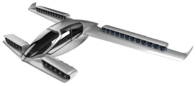
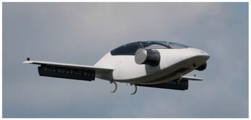
Another heavily promoted concept at the time of writing is the Lilium Jet, illustrated in Figs. 21 and 22. There are fewer details published, although it is claimed to have a top speed of around 300km/h with a pilot and four passengers, equivalent to a fast helicopter. This concept aims to be a fully battery-powered air-taxi aircraft.
Lilium Jet.

Lilium Jet prototype.

Vertical thrust is achieved by rotating the fan units about a hinge point along their leading edge. This has a benefit of reducing the effective wing area in hover and, thus, reducing the lift loss, and the placement on the trailing edge boosts the wing effectiveness through transition, although pitching moments would have to be carefully managed. From an aerodynamic point of view, this looks to be a good solution to a VTOL aircraft that transitions to wing-borne flight.
A prototype of a two-seat variant of the Lilium Jet has flown as a remotely piloted vehicle and has demonstrated transition to forward flight and back. The flight control system clearly works, which is a great achievement.
However, from the discussions earlier in the paper, the disc area is visibly very low compared to a helicopter, meaning that hover efficiency will be low. In fact, assuming a 10% thrust margin, the data posted on Wikipedia for the prototype would give a hover lift efficiency of 21.6 N/kW. This translates to a disc loading in the region of 5,200 N/m2, which is rather higher even than the TriFan 600, resulting in a rather high jet velocity from the fans to achieve the required thrust. For an air-taxi type of aircraft, this has potential implications for community noise. The biggest issue, though, is the use of battery power for such a low hover efficiency, as the mass of the batteries needed for VTOL operation will have a heavy impact on useful payload.
9.4 DeLorean DR7
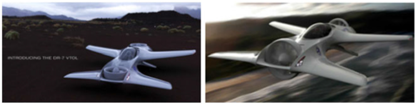
This concept, shown in Fig. 23, was one of the more unusual I found when researching this article. It is a tandem seat eVTOL aircraft with claimed autonomous control and a top speed of 380 km/h. It looks more like a fun sport aircraft but could conceivably be used as a commuter aircraft. There are no details on weights and powers, etc. From an aerodynamic point of view, the induced effects of the two lift fan intakes at least balance each other out and being at the extremities of the aircraft should minimise lift losses. However, as with the TriFan 600, there are likely to be some big pitching moment changes generated by the jet from the front fan as it encounters and traverses across the fuselage.
DeLorean DR7.

10.0 CONCLUSIONS
This paper has sought to show some of the induced aerodynamic effects associated with VTOL aircraft that transition to wing-borne flight based on examples from the author’s past experience. Such effects may not be show stoppers for future concepts, but they need to be understood and accounted for from early in the conceptual design phase.
We have discussed the importance of disc loading and hover lift efficiency in defining the installed power needed to hover. If the disparity between power needed to hover and power required for forward flight is too great, then the compromises in the design will have a strong negative impact on overall mission performance.
The prospects for electric propulsion have been considered. While electric motor technology has progressed significantly in recent years, battery technology is a long way from matching the energy and power density of liquid hydrocarbons. There is a basic incompatibility between battery capability and the hover disc loading needed for a high-speed cruise configuration.
An additional element to be considered is the aeromechanical loading on propellers at incidence, which would start to become a serious issue for multicopter concepts capable of carrying people and for ducted fan concepts that transition to wing-borne flight.
For the purposes of this paper, the VTOL dream is defined as a (relatively) simple and cheap to operate aircraft able to perform inter-city missions at turboprop aircraft speeds. Although advances have been made and some of the concepts are looking promising, this particular dream still seems a long way off.