Introduction
Polymer electrolyte fuel cells (PEFCs)Reference Strasser1 are an important class of fuel cells because their characteristics, such as high power density, low operation temperature, short startup time, small size, and light weight, make them promising candidates for use in domestic and vehicle power sources. However, their high production cost is the most serious bottleneck for wide application and commercialization. Therefore, the main goal of recent studies on PEFCs has been the reduction of cost.Reference Alayoglu, Nilekar, Mavrikakis and Eichhorn2–Reference Ishihara, Ohgi, Matsuzawa, Mitsushima and Ota4 One solution is operating PEFCs under high temperatures (>100°C) without humidification. The expected benefits of such a system are that a water management system is not required, and high utilization of waste heat, easy thermal control by a radiator, reduction of CO poisoning, and improvement of activity of a Pt catalyst are realized.Reference Li, He, Jensen and Bjerrum5 In a conventional humidified PEFC system, a polymer electrolyte membrane, such as Nafion, has sulfonic acid groups in its chemical structure. By absorbing water, the sulfonic acid groups can dissociate, and the resultant hydronium cations conduct protons.Reference Mauritz and Moore6 Therefore, conventional PEFCs should usually be operated at temperatures lower than 80°C with humidification to keep water inside the membranes. In order to develop non-humidified intermediate-temperature fuel cells, new anhydrous proton conductors should be explored as an alternative to aqueous systems.
Ionic liquids (ILs) are molten salts that exhibit melting temperatures (T m) at around room temperature (also see the Introductory article in this issue).Reference Rogers and Seddon7–Reference Seddon9 Typical ILs (e.g., 1-methyl-3-ethylimidazolium bis(trifluoromethanesulfone)imide ([C2mim][NTf2] or [C2mim][TFSI])) exhibit high thermal stability (>300°C), negligible vapor pressure, and nonflammability.Reference Noda, Hayamizu and Watanabe10 Additionally, ILs can self-dissociate,Reference Tokuda, Tsuzuki, Susan, Hayamizu and Watanabe11 thus exhibiting high ionic conductivity even in the absence of a molecular solvent, which may interfere with the advantages of ILs (e.g., thermal stability).Reference Nakata, Kohara, Matsumoto and Hagiwara12 These unique characteristics are desirable for electrolytes in electrochemical devices such as lithium batteries, electric double layer capacitors, and dye sensitized solar cells, since such devices should be safer and more stable (see the Navarra article in this issue).Reference Sakaebe and Matsumoto13–Reference Grätzel16
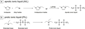
ILs can be categorized into two groups: Typical ILs, such as [C2mim][NTf2], are generally synthesized by the quaternization (alkylation) of the corresponding amine, followed by an anion exchange reaction (Scheme 1a). Such ILs have no exchangeable protons (i.e., no active protons) in their chemical structure and are thus called aprotic ionic liquids (AILs). On the other hand, ILs that are typically synthesized by the neutralization reactions of a Brønsted acid (proton donor) and a Brønsted base (proton acceptor) (Scheme 1b) have exchangeable (active) protons and are called protic ionic liquids (PILs).Reference Greaves and Drummond17 PILs generally show similar characteristics to AILs. However, the active protons induce hydrogen bonding in PILs, which allows for unique applications. The Angell group and other research groups have reported the preservation of proteins in PILs.Reference Byrne and Angell18,Reference Kumar and Venkatesu19 According to their reports, hydrogen bonding prevents the denaturation of proteins and maintains their higher-order structure. Formation of micelles in ethylammonium nitrate has also been reported.Reference Evans, Yamauchi, Roman and Casassa20–Reference Hayes, Imberti, Warr and Atkin23
Typical synthetic routes for ionic liquid. Aprotic ionic liquids are synthesized by quaternization reaction (alkylation) of imidazole (or amine), followed by anion exchange reaction (a), while protic ionic liquids are synthesized by neutralization reaction between the Brønsted acid and base (b). Note: TFSI, bis(trifluoromethanesulfonyl)imide.

We have focused on the active protons in PILs and have tried to employ them as proton conductors for non-humidifying intermediate-temperature fuel cells. Following our report on the activity of PILs on fuel cell electrode reactions, several groups have started their studies in this field as well.
Water-like properties
Proton transport properties
Proton conductivity is an essential property of electrolytes for fuel cells. Two proton conduction mechanisms have been proposed. In acidic aqueous solutions (typical proton conductors), protons exist as hydronium cations. Thus, the diffusion of protons is achieved by the diffusion of hydronium cations. This mechanism is called the vehicle mechanism. On the other hand, protons can also move by hopping through a hydrogen-bonded network formed by hydronium cations and water molecules. This mechanism is called the Grotthuss mechanism.Reference von Grotthuss24Figure 1 depicts these two proton conduction mechanisms.Reference Kreuer, Rabenau and Weppner25 It is known that proton movement can be faster in the Grotthuss mechanism than in the vehicle mechanism, and the former mechanism works when the proton donor and acceptor coexist and form strong hydrogen bonding networks. Kreuer and co-workers have investigated the transport properties of aqueous HCl,Reference Kreuer, Paddison, Spohr and Schuster26,Reference Dippel and Kreuer27 and Figure 2 shows the diffusion coefficients of water and protons as a function of HCl concentration. The difference between the diffusion coefficients of protons (D σ) and water  $\left( {D_{H_2 } _O } \right)$ corresponds to the contribution of proton conduction by the Grotthuss mechanism, and it was found that this contribution decreases with increasing acid concentration.
Illustration of proton conduction in acidic aqueous solutions and in protic ionic liquids. The men represent water or base, while the balls represent protons.Reference Kreuer, Rabenau and Weppner25

Diffusion coefficient of protons (D σ) and water self-diffusion coefficient ( $\left( {D_{H_2 } _O } \right)$) in aqueous HCl as a function of acid concentration (M). The deviation between D σ and
 $D_{H_2 } _O $ corresponds to proton diffusion by the Grotthuss mechanism, while
 $D_{H_2 } _O $ corresponds to that by the vehicle mechanism. The contribution by the Grotthuss mechanism for proton diffusion decreases when increasing the acid concentration.Reference Kreuer, Rabenau and Weppner25 Note: D, diffusion coefficient.

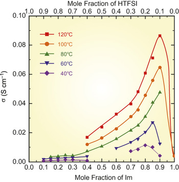
We investigated the transport properties of mixtures of imidazole (Im) and bis(trifluoromethane sulfone)imide acid (HNTf2 or HTFSI).Reference Noda, Susan, Kudo, Mitsushima, Hayamizu and Watanabe28 Among the mixtures of acid and base, 1:1 salts can be PILs. On the other hand, ordinary acidic aqueous solutions are mixtures containing excess water (base). Here, in order to make a comparison investigation on the mixtures of Im and TFSI with various compositions is shown. When the difference between the acid dissociation constants (pK a) of a Brønsted acid and a Brønsted base (ΔpK a) is sufficiently high, we can assume that Im is completely protonated to imidazolium cation ([Im]) in a 1:1 salt (molar ratio). However, ionic conductivity reaches a maximum when the molar ratio of Im is 0.8−0.9 (Figure 3). Table I lists the diffusion coefficients determined by pulsed gradient spin-echo nuclear magnetic resonance (NMR) techniques.Reference Noda, Susan, Kudo, Mitsushima, Hayamizu and Watanabe28 It was revealed that the diffusion coefficient of the N–H proton (D N–H) is greater than that of the C–H (D C–H) proton in compositions with excess Im. This difference corresponds to the contribution of the Grotthuss mechanism. On the other hand, in the case of compositions with excess HNTf2, the values of D C–H and D N–H are low and identical. This result indicates that the proton conduction mainly occurs by the vehicle mechanism in compositions with excess HNTf2. The Grotthuss mechanism contributes to proton conduction for compositions with excess Im, where [Im] and Im are hydrogen-bonded together and serving as a proton donor and acceptor, respectively. However, such base-rich compositions are not preferable because of their poor thermal stability.
Ionic conductivity (σ) of Im/HNTf2 (HTFSI) mixtures as a function of molar fraction of imidazole (Im). σ shows peaks at 0.8∼0.9 of molar fraction of Im.Reference Noda, Susan, Kudo, Mitsushima, Hayamizu and Watanabe28 Note: HNTf2, bis(trifluoromethane sulfone)imide acid.

Diffusion coefficients of protons and fluorine in imidazole/bis(trifluoromethanesulfonyl)amide acid (Im/HNTf2) mixtures.

D N–H and D C–H indicate diffusion coefficients of N–H and C–H protons of Im and imidazolium cation ([Im]) (indistinguishable by nuclear magnetic resonance [NMR]), and D C–F and  $D_{{\rm{H - HNTf}}_{\rm{2}} } $ indicate the diffusion coefficients of fluorine and protons of HNTf2 and [NTf2] (indistinguishable by NMR), respectively. Note: D, diffusion coefficient.
Electrochemical activities
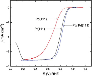
Another important property of fuel cell electrolytes is the activity of fuel cell electrode reactions (i.e., the hydrogen oxidation reaction [HOR] and oxygen reduction reaction [ORR]). Figure 4 shows polarization curves for ORR in a 0.1 M perchloric acid (HClO4) aqueous solution with a single crystal surface (111) of different metal-wire working electrodes under oxygen.Reference Zhang, Mo, Vukmirovic, Klie, Sasaki and Adzic29 As can be seen from this figure, reductive currents corresponding to ORR are observed under O2. The reason for the onset potential of ORR being lower than the theoretical value (1.23 V versus reversible hydrogen electrode at 25°C) even in the case of Pt/Pd(111), which shows the highest activity among these three electrodes, is oxide formation on the metal surface, in addition to the slow kinetics of ORR. For ORR, “protonated water” (hydronium cation) is considered to play an important role, suggesting that the reactivity of the protonated base is a key point in electrode reactions of non-aqueous systems.
Polarization curves of oxygen reduction reaction (ORR) measured in a 0.1 M HClO4 using different working electrodes (Pd(111), Pt(111), and Pt/Pd(111)) for a comparison of solution kinetics. The sweep rate for Pd(111) and Pt/Pd(111) is 20 mV/s, while for Pt(111) it is 50 mV/s.Reference Zhang, Mo, Vukmirovic, Klie, Sasaki and Adzic29 Though Pt/Pd(111) shows the best activity on ORR among the three electrodes, the onset potential for ORR is lower than 1.0 V. Note: j, current density; E, potential versus RHE (reversible hydrogen electrode).

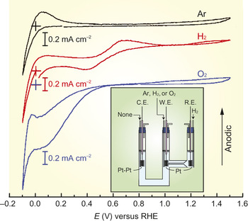
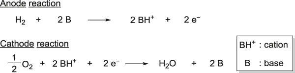
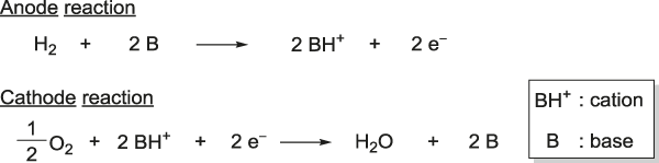
Fortunately, for the first time, we could find faradaic current corresponding to the fuel cell electrode reactions in 1:1 salt of [Im][NTf2] at 130°C under anhydrous conditions (Figure 5),Reference Susan, Noda, Mitsushima and Watanabe30 although both HOR and ORR were sluggish. From this result, we claimed that PILs can be employed as non-aqueous proton conductors for fuel cells, and this has facilitated ongoing research on non-humidified intermediate-temperature fuel cells using PILs. Plausible electrode reactions in PILs are shown in Scheme 2.
Cyclic voltammograms measured in [Im][NTf2] (imidazole/ bis(trifluoromethane-sulfonyl)amide acid) using a Pt wire working electrode at 130°C under H2, O2, or Ar at saturated conditions. Inset depicts the structure of a three electrode cell used for the measurements.Reference Noda, Susan, Kudo, Mitsushima, Hayamizu and Watanabe28 Note: C.E., counter electrode; W.E., working electrode; R.E., reference electrode; E, potential versus RHE; RHE, reversible hydrogen electrode.

Plausible fuel cell electrode reactions in protic ionic liquids.
Properties different from those of water
Proton conductivity and activity of fuel cell electrode reactions of PILs appear to be somewhat analogous to those of acidic aqueous systems. On the other hand, the wide variety of molecular designs for realizing favorable fuel cell electrolytes is a unique and promising feature of PILs. So far, many research groups have studied a number of different AILs and have tried to correlate their physicochemical properties with chemical structures.Reference Tokuda, Tsuzuki, Susan, Hayamizu and Watanabe11,Reference Tokuda, Hayamizu, Ishii, Susan and Watanabe31–Reference Huddleston, Visser, Reichert, Willauer, Broker and Rogers37 In the case of PILs, one of the most important parameters defining the physicochemical properties is ΔpK a, since ΔpK a directly affects the acid-base equilibrium. Angell and co-workersReference Yoshizawa, Xu and Angell38 reported that the thermal stability of PILs increases with increasing ΔpK a, and Dai et al. reported that PILs prepared from an organic strong base, 1,5-diazabicyclo[4.3.0]non-5-ene, and a superacid exhibit extremely high thermal stability comparable to that of [C2mim][NTf2].Reference Luo, Baker, Lee, Pagni and Dai39 Angell and co-workers also found the optimum ΔpK a of PILs in terms of the magnitude of open circuit voltage (OCV) of H2/O2 fuel cells. We confirmed the relationship between the physicochemical properties and ΔpK a, and concluded that a ΔpK a value higher than 15 is essential for obtaining sufficient thermal stability of PILs.Reference Miran, Kinoshita, Yasuda, Susan and Watanabe40 The OCV of H2/O2 fuel cells exhibited a maximum at ΔpK a = 16−18. Therefore, PILs with ΔpK a = 16−18 can be expected to be suitable for fuel cell applications.Reference Miran, Yasuda, Susan, Dokko and Watanabe41
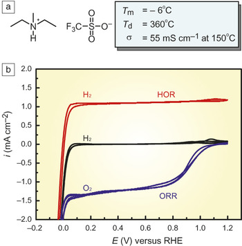
Through the screening of more than 100 different PILs, it has been found that diethylmethylammonium trifluoromethanesulfonate ([dema][TfO]) exhibits a low melting point (T m = −6°C), wide liquid temperature range (decomposition temperature T d = 360°C), and high ionic conductivity (55 mS cm−1 at 150°C under anhydrous conditions) (Figure 6a).Reference Nakamoto and Watanabe42 Proton transport in the bulk fundamentally occurs through the vehicle mechanism. Importantly, a H2/O2 fuel cell using [dema][TfO] at 150°C reaches an OCV of 1.03 V, which indicates facile HOR and ORR reactions that cannot be achieved in aqueous systems (Figure 6b).
(a) Chemical structure and bulk properties of (diethylmethylammonium trifluoromethanesulfonate) [dema][ TfO], and (b) cyclic voltammograms measured at 150°C under H2 or O2 under saturated conditions. The onset potentials of oxygen reduction reaction (ORR) and hydrogen oxidation reaction (HOR) are ca. 1 V and ca. 0 V versus RHE, respectively.Reference Miran, Kinoshita, Yasuda, Susan and Watanabe40 Note: T m, melting temperature; T d, decomposition temperature; σ, ionic conductivity; i, current density; E, potential from RHE; RHE, reversible hydrogen electrode.

Fuel cells using PILs
Membrane fabrication
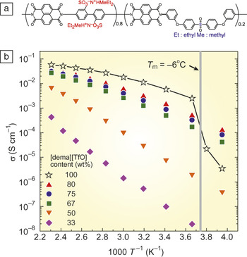
In order to apply PILs to practical fuel cells, fabrication of solid thin films containing electrolytes is essential. We have reported several solidification methods for ILs.Reference Michot, Nishimoto and Watanabe43–Reference Lee, Yasuda and Watanabe46 However, the requirements for fuel cell electrolyte membranes, such as high mechanical strength, good gas barrier properties, and high thermal, chemical, and electrochemical stability, are difficult to attain, and thus the choice in terms of the solidification methods is limited. We found that sulfonated polyimide (SPI) in ammonium form shows good compatibility with [dema][TfO] and yields flexible and mechanically strong composite membranes upon casting from a m-cresol solution, including proper amounts of SPI and [dema][TfO].Reference Lee, Yasuda and Watanabe46 Interestingly, it was found that the compatibility of SPI with [dema][TfO] increases with an increase in ion exchange capacity (IEC), and thus the SPI with an IEC of 2.15 meq g−1 (Figure 7a) can retain an amount of [dema][TfO] in terms of weight that is four times higher than the weight of SPI.Reference Lee, Ogawa, Kanno, Nakamoto, Yasuda and Watanabe47Figure 7b shows the ionic conductivity of composite membranes under anhydrous conditions, which increases with increasing [dema][TfO] content. While composite membranes with [dema][TfO] content lower than 50 wt% exhibit a large temperature dependence of ionic conductivity, this dependence becomes relatively low, with [dema][TfO] content higher than 67 wt%. To achieve higher ionic conductivity, the effect of the chemical structure of SPI was investigated.Reference Yasuda, Nakamura, Honda, Kinugawa, Lee and Watanabe48 It was found that the composite membranes (50 wt% of [dema][TfO] and IEC of 1.2−1.4 meq g−1) prepared from SPI with a pendant sulfoalkyl side chain and multi-block SPI exhibited higher ionic conductivity at a lower temperature (6.9 × 10⁻⁶ S cm−1 and 1.2 × 10⁻⁵ S cm−1 at 40°C, respectively) than those based on random main-chain SPI (1.7 × 10⁻⁶ S cm−1 at 40°C). Atomic force microscope phase images revealed highly developed phase separation between ionic and nonionic moieties.Reference Yasuda, Nakamura, Honda, Kinugawa, Lee and Watanabe48 Thus, we assume that the conductivity difference, depending on the chemical structure, can be explained by the connectivity of ion-conducting channels in the composite membranes. There will still be room for finding a suitable chemical structure for SPI as a matrix polymer.
(a) Chemical structure of sulfonated polyimide and (b) temperature (T) dependence of ionic conductivity (σ) of composite membranes under anhydrous conditions. σ of the composite membranes increases with increasing [dema][TfO] content, and thus, pure [dema][TfO] shows the highest ionic conductivity. However, at temperatures lower than the melting point (indicated by the gray line), pure [dema][TfO] shows lower ionic conductivity than that of composite membranes with [dema][TfO] higher than 50 wt%. Note: [dema][TfO], diethylmethylammonium trifluoromethanesulfonate.Reference Lee, Ogawa, Kanno, Nakamoto, Yasuda and Watanabe47

Interestingly, the T m of [dema][TfO] (−6°C) was not detected for the composite membranes, except for the one containing 80 wt% of [dema][TfO], due to the confinement effect that restricts crystallization in nano-sized space.Reference Loo and Register49,Reference Sun, Zhu, Ge, Quirk, Xue, Cheng, Hsiao, Aviala-Orta, Sics and Cantino50 This phenomenon enables using the composite membranes at temperatures lower than the T m of [dema][TfO]. Figure 7b clearly shows the higher ionic conductivity of composite membranes compared with that of pure [dema][TfO] at temperatures below the T m of [dema][TfO].
Fuel cell operation
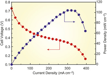
We examined non-humidifying H2/O2 fuel cell operation using composite membranes at intermediate temperatures.Reference Lee, Ogawa, Kanno, Nakamoto, Yasuda and Watanabe47 First, we tried to fabricate a membrane-electrode-assembly. It could be expected that a Nafion ionomer will not work under non-humidifying conditions at temperatures higher than 100°C. Thus, a catalyst layer for a phosphoric acid fuel cell, wherein a fluorocarbon polymer is employed as a binder, was chosen. Fuel cell operation was tested under non-humidified conditions at 120°C. Before recording a polarization curve, an aging process was required, since [dema][TfO] could leak out during the aging process from the composite membrane acting as an ion conducting layer, forming a three-phase boundary in the catalyst layer. Figure 8 shows the polarization curve under non-humidifying conditions. The maximum current and power densities are 400 mA cm−2 and ca. 100 mW cm−2, respectively.Reference Yasuda, Nakamura, Honda, Kinugawa, Lee and Watanabe48 We assume that the maximum current density is limited by mass transfer. One possible reason is insufficient gas supply. In this experiment, the utilization of O2 gas reached ca. 80% at the maximum current. However, it was found that an increase in the gas flow rate led to a decrease in the cell potential. As mentioned previously, an unstable three-phase boundary in the catalyst layer is formed by leaked [dema][TfO], and this boundary is strongly affected by the environment of the catalyst layer, such as gas flow rate, temperature, and current density. For further improvement of fuel cells using PILs, a catalyst layer consisting of stable anhydrous proton-conducting material needs to be developed.
Polarization curve of H2/O2 non-humidifying fuel cell using a sulfonated polyimide/[dema][TfO] (diethylmethylammonium trifluoromethanesulfonate) composite membrane at 120°C. The maximum current density is 400 mA cm−2, while the maximum power density is ca. 100 mW cm−2.Reference Yasuda, Nakamura, Honda, Kinugawa, Lee and Watanabe48

Potential of PILs as fuel cell electrolytes
Finally, we discuss the potential of fuel cells using PILs. The ratio of proton conductivity to total ionic conductivity (proton transference number (t +)) is an important parameter in determining the performance of a fuel cell electrolyte. In the case of hydrated sulfonated polymer electrolyte membranes such as Nafion, t + is 1.0, because the counter anions (i.e., sulfonate groups) are affixed to the polymer backbone. On the other hand, t + of the present PILs is 0.5−0.6,47 which is unfavorable for fuel cell electrolytes, because low t + results not only in low proton conductivity but also in the polarization of fuel cells. However, the proton conduction mechanism of PILs under fuel cell operation can differ from that in bulk, because free amine, diethylmethylamine, is continuously generated at the cathode by ORR between [dema] and oxygen to generate water (Scheme 2). The free amine can accept a proton, and thus a proton-exchange reaction between the free amine and [dema] is possible.
A simulation of the fuel cell operation conditions was performed using a 1:1 salt of N,N,N′,N′-tetramethylethylenediamine and trifluoromethanesulfonic acid, which is a half-protonated diamine.Reference Lee, Ogawa, Kanno, Nakamoto, Yasuda and Watanabe471H-NMR spectra and thermogravimetric measurements under heating showed indistinguishable proton signals of amine and ammonium structures, and the formation of diammonium salt and concomitant evaporation of diamine, respectively. This result showed the existence of a proton-exchange reaction at the faster time scale of the NMR measurements. During the fuel cell operation, free amine is generated continuously. If there is no proton-exchange reaction, the free amine diffuses back to the anode and accepts the protons generated in the HOR. Judging from the diffusivity of the cation (ca. 10–6 cm2 s–1), it takes roughly 104 s for an amine molecule to diffuse over a 1 mm distance. Because the free amine is thermally quite unstable, it evaporates easily, resulting in the decomposition of the electrolyte. It is quite plausible that the proton-exchange mechanism is responsible for the proton transport under fuel cell operation.Reference Lee, Ogawa, Kanno, Nakamoto, Yasuda and Watanabe47
The electrochemical characterization of PILs has just begun, and only a few studies have been reported so far.Reference Noda, Susan, Kudo, Mitsushima, Hayamizu and Watanabe28,Reference Johnson, Ejigu, Licence and Walsh51 A difficulty in this research is that impurities such as water and small deviations in the acid/base compositions from 1/1 may seriously impact the properties. However, it should be noted that facile electrochemical activity for HOR and ORR is seen for [dema][TfO] in a wide temperature range (from 30°C to 170°C), as typically shown in Figure 6b.
PILs are liquid electrolytes, and thus, leakage from membranes is another issue during fuel cell operation, where water is generated by the electrode reactions. If PILs are hydrophilic, such a problem will become more pronounced. Hydrophobic PILs (i.e., water-immiscible PILs) can be prepared easily by using the [NTf2] anion. They show good thermal stability and high ionic conductivity. However, such PILs do not exhibit good electrochemical activity.Reference Lee, Ogawa, Kanno, Nakamoto, Yasuda and Watanabe47 The OCV of H2/O2 fuel cells using PILs depends strongly on ΔpK a and exhibits a maximum at ΔpK a = 16−18 (vide supra). Ethylmethylpropylammonium nonafluorobutanesulfonate ([empa][NfO]) fulfills this requirement, and it is hydrophobic.Reference Yasuda, Ogawa, Kanno, Mori, Sakakibara and Watanabe52 Furthermore, we succeeded in fuel cell operation using [empa][NfO]/SPI composite membranes.Reference Yasuda, Nakamura, Lee and Watanabe53
Conclusion
In this article, the characteristics of protic ionic liquids (PILs) as electrolytes for non-humidified intermediate-temperature fuel cells were compared with those of acidic aqueous solutions. Studies on developing PIL-based fuel cell electrolytes are briefly described. A wide range of possible molecular designs for fuel cell electrolytes is one of the unique characteristics of PILs. Similar to acidic aqueous solutions, PILs exhibit proton conductivity and activity for fuel cell electrode reactions. Excess base can induce the Grotthuss mechanism for proton conduction. However, such compositions are not preferable, since excess base significantly lowers the thermal stability. The thermal stability and open circuit voltage (OCV) of H2/O2 fuel cells using PILs are greatly affected by ΔpK a. PILs with ΔpK a higher than 15 exhibit excellent thermal stability high enough for intermediate-temperature fuel cell applications, while the OCV exhibits a maximum at ΔpK a = 16−18. We conclude that PILs with ΔpK a = 16−18 are suitable for fuel cell applications. From the screening of more than 100 different PILs, diethylmethylammonium trifluoromethanesulfonate ([dema][TfO]) was chosen for fuel cell applications due to its excellent bulk properties and low overpotentials in fuel cell reactions. We found that sulfonated polyimide in ammonium form exhibited good compatibility, gave flexible and mechanically strong composite membranes, and was successfully used in non-humidifying fuel cell operation at 120°C. It was also found that hydrophobic water-immiscible ethylmethylpropylammonium nonafluorobutanesulfonate ([empa][NfO]) could be successfully used in fuel cell operation at 120°C without humidification. PILs are thus possible candidates for non-humidifying intermediate-temperature fuel cells. To further improve the fuel cell performance using ILs, establishing a suitable catalyst layer under non-humidified conditions is required.
Acknowledgments
This work was financially supported by a Grant-in-Aid for Scientific Research in the Priority Area “Science of Ionic Liquids” from MEXT of Japan and by the Technology Research Grant Program from NEDO of Japan.