1. Introduction
In recent years, the development of limited degrees of freedom (DOF) parallel manipulators (PMs) has been the focus of attention of many researchers. These type of robots hold the core strengths of PMs and, furthermore, have a simpler kinematic structure, lower implementation expense, and higher functionality. Among the proposed structures, translational parallel manipulators (TPMs) and spherical parallel manipulators (SPMs) are noteworthy, in which the moving platform has a purely transitional or purely rotational motion, respectively. The industrial applications of TPMs include rapid pick and place tasks, machining tools, and assembly operations [Reference Hamida, Laribi, Mlika, Romdhane and Zeghloul1], while the popular usages of SPMs consist of 3D camera stabilizers and minimally invasive surgical robots [Reference Bataleblu, Khorrambakht and Taghirad2].
Among limited DOF PMs, some 3-universal prismatic universal (3-UPU) PMs have attracted the attention of robotics researchers because of their special kinematical properties [Reference Gregorio3]. In these robots, the robot consists of 3 limbs, and each limb is composed of a prismatic joint connecting the moving platform to the base frame. Therefore, the motion of the moving platform is controlled by a prismatic actuator. Among the kinematic structures developed based on this robot, TPM [Reference Hu, Yao, Wu and Lu4], SPM [Reference Gregorio5], and mixed translational and rotational motions [Reference Lu, Shi and Hu6] may be listed.
The main purpose of this study is to derive the explicit dynamics formulation for a 3-UPU TPM introduced first by Tsai in ref. [Reference Tsai7]. The main features of this robot in terms of inverse and forward kinematic analysis, workspace analysis, and kinetostatic analysis are reported in refs. [Reference Tsai and Joshi8–Reference Chebbi, Affi and Romdhane10]. Moreover, the challenging issues in the design structure are discussed in refs. [Reference Han, Kim, Kim and Park11–Reference Hraiech, Chebbi, Affi and Romdhane13], while the implementation feasibility of this robot is examined in refs. [Reference Bhutani and Dwarakanath14, Reference Bhutani and Dwarakanath15].
In general, dynamics analysis of TMs is more complicated than serial manipulators due to the existence of closed kinematic chains. Therefore, research on the dynamics of parallel robots is fewer than that of kinematic studies. The dynamic analysis of robots, however, is crucial for dynamic performance analysis, robots’ mechanical design, model-based controller design, and robot calibration schemes. As representatives of the researches carried out on the dynamic analysis of the 3-UPU TPM, representative research works [Reference Staicu and Popa16–Reference Hu, Lu and Mao19] may be listed. In refs. [Reference Staicu and Popa16, Reference Hraiech, Houidi, Affi and Romdhane17], Staicu and El Hraiech have used the Lagrange multipliers method to analyze the robot dynamics, and in ref. [Reference Hraiech, Chebbi, Affi and Romdhane18], the robot’s implicit dynamics is derived using the Newton-Euler method to evaluate the robot’s dynamic errors, as a function of the uncertainties of the design parameters. Moreover, Hu examined the implicit dynamics of two3-UPU robots using the principle of virtual work in ref. [Reference Hu, Lu and Mao19]. Among the intensive studies of 3-UPU SPMs, we may mention the ref. [Reference Xiangzhou, Yougao and Hongzan20], which has used the principle of virtual work for implicit dynamicanalysis.
Generally, derivation of the explicit form of robot dynamics using the Newton-Euler method is not recommended since it requires derivation and elimination of the constraint forces [Reference Taghirad21, Reference Tsai22]. Likewise, the Lagrange method necessitates taking partial derivatives of the mass matrix analytically to extract Coriolis terms, which is a prohibitive task [Reference Kalani, Rezaei and Akbarzadeh23]. In the virtual work approach, first, each link’s linear and angular accelerations are extracted, and the inertial forces and moments are derived. Next, by using D’Alembert’s principle, the entire robot may be assumed to be at static equilibrium, and by utilizing the principle of virtual work, the actuator forces may be derived. This approach has lower computational cost in comparison to that of other methods [Reference Arian, Danaei, Abdi and Nahavandi24, Reference Mazare, Taghizadeh and Najafi25].
Although the analysis of implicit dynamics of 3-UPU TPM has been studied in the literature, to the best of the authors’ knowledge, no previous study has investigated the explicit dynamics of this manipulator. In the explicit dynamic model, robot dynamics are required to be derived by three principal components, mainly the mass matrix, the centrifugal and Coriolis matrix, and the robot gravity vector [Reference Oftadeh, Aref and Taghirad26]. However, in the previous studies on the dynamic analysis of 3-UPU TPM, these terms are not extracted and at most the inverse dynamicsFootnote 1 equations are extracted. With the advantages of explicit dynamics extraction, many advanced model-based controllers, such as inverse dynamic controller (IDC) [Reference Taghirad21], robust inverse dynamic controller (RIDC) [Reference Shang and Cong27, Reference Bataleblu, Motaharifar, Abedlu and Taghirad28], adaptive robust controller (ARC) [Reference Babaghasabha, Khosravi and Taghirad29], and adaptive sliding mode control (ASMC) [Reference Zeinali and Notash30], can be designed and implemented on 3-UPU TPM. Nonetheless, in the absence of sufficient knowledge of the explicit dynamic model of the robot, only simple and effective model-free controllers such as PD and PID can be utilized. These controllers are configuration-dependent, and their tuning for the whole workspace is very difficult. Moreover, their performance would be limited compared to the controllers using the dynamic knowledge of the robot [Reference Taghirad21]. In ref. [Reference Paccot, Andreff and Martinet31], an in-depth review of the performance of model-free and model-based controllers in PMs is provided.
The main contribution of this paper is to derive an explicit dynamics model of the 3-UPU TPM applicable in the robot’s controller design. However, it should be noted that due to the presence of universal joints in the robot, there are some angular velocity terms for each limb, which are wrongly ignored in the literature of 3-UPU TPM, to simplify the kinematic and dynamic equations of the robot [Reference Hraiech, Chebbi, Affi and Romdhane18, Reference Xiangzhou, Yougao and Hongzan20]. Although this assumption simplifies the robot’s kinematic analysis, the robot’s dynamics model would lose its precision. As a result, in this paper, first, all the kinematic terms affecting the 3-UPU TPM are determined in detail. Furthermore, the principle of virtual work is used to extract the implicit dynamics of the 3-UPU TPM. Then, using this method and the kinematic analysis of each limb by corresponding Jacobian matrix, the explicit formulation of the robot dynamics is derived, and the properties required to design the model-based controllers are proven.
By this formulation, it is possible to develop a wide range of advanced model-based controllers, which can compensate the uncertainties in the 3-UPU TPM kinematic/dynamic model, such as robust inverse dynamic control [Reference Shang and Cong27], and adaptive sliding mode control [Reference Zeinali and Notash30]. Additionally, one of the main advantages of the virtual work method over other common methods of dynamic analysis of PMs is its freedom to the constraint and internal forces, which causes the number of dynamic equations to be significantly fewer. Analogously, in the virtual work method, there is no need to derive the partial derivatives of the mass matrix in order to extract the centrifugal and Coriolis vector [Reference Tsai22, Reference Kalani, Rezaei and Akbarzadeh23, Reference Mazare, Taghizadeh and Najafi25]. Furthermore, by using the loop closure equations as a method for kinematic analysis, we can derive the explicit dynamic model in a more straightforward form, while avoiding complexities of approaches like screwtheory [Reference Tsai22].
The remainder of this paper is organized as follows. The kinematics analysis results are given in the following section. Differential and acceleration analysis is presented in Sections 3 and 4, while Section 5 represents the dynamic analysis of the robot. Then, the simulation and results verified through MSC ADAMS® software are given in Section 6. Finally, the concluding remarks are given in the last section.
2. Kinematic Analysis
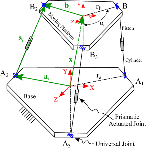
The 3-UPU TPM considered in this paper possess a symmetrical structure composed of three kinematic chains in which each limb is composed of a cylinder and a piston, which are connected together by a prismatic joint. The connection joint between each limb and the base, as well as the moving platform, is a universal joint consisting of two revolute joints with concurrent and perpendicular axes. The centers of the universal joints are also placed at an angle of
 $\alpha=120^\circ$
from each other. A schematic of the considered 3-UPU TPM can be seen in Fig. 1.
Schematic of a 3-UPU manipulator.

It is assumed that the attachment points
 $A_i$
and
 $B_i$
lie on
 $X-Z$
and
 $x-z$
planes, respectively. Hence, with respect to the base frame coordinate, the position vectors
 $A_i$
and
 $B_i$
, can be shown as
 $\boldsymbol{{a}}_i=\boldsymbol{{R}}_y(\alpha_i) [0,0,r_a]^T$
and
 $\boldsymbol{{b}}_i=\boldsymbol{{R}}_y(\alpha_i) [0,0,r_b]^T$
, respectively. Moreover,
 $\boldsymbol{{x}} =[x_p, y_p,z_p]^T$
is considered as the task space variables, while
 $\boldsymbol{{q}} = [d_1, d_2,d_3]^T$
denotes the robot prismatic joint variables. Furthermore, it is proven that the moving platform has pure translational movement, when the axes of the two universal joints of each limb are perpendicular to the axis of the prismatic joint and also parallel to eachother [Reference Tsai and Joshi8].
2.1 Inverse kinematics
According to Fig. 1, for i = 1,2,3, each limb loop closure equation can be shown as the following:
 \begin{equation} \boldsymbol{{s}}_i= \ell_{i} \hat{\boldsymbol{{s}}}_i=\boldsymbol{{x}}+\boldsymbol{{b}}_i-\boldsymbol{{a}}_i,\end{equation}
in which
 $\hat{\boldsymbol{{s}}}_i$
is defined as a unit vector along the direction of the limb i. Hence, joint variable,
 $\ell_i$
, may be derived as
 $ \ell_i=\sqrt{\left [\boldsymbol{{x}}+\boldsymbol{{b}}_i-\boldsymbol{{a}}_i\right]^T \left [\boldsymbol{{x}}+\boldsymbol{{b}}_i-\boldsymbol{{a}}_i\right]} $
.
2.2 Rotation matrix analysis
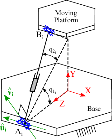
In each closed kinematic chain, there are two passive angles,
 $q_{1_i},q_{2_i}$
, which are related to the revolute joints of each universal joint. According to Fig. 2, these angles can be derived as follows:
 \begin{align} q_{1_i}=atan2 \left( {^{i}\mathrm{\boldsymbol{{s}}}_{y_i}},{-^{i}\mathrm{\boldsymbol{{s}}}_{z_i}} \right),\end{align}
 \begin{align} q_{2_i}=asin \left( {^{i}\mathrm{\boldsymbol{{s}}}_{x_i}}/{\ell_i} \right), \end{align}
in which,
 ${}^{i}\mathrm{\boldsymbol{{s}}}_{i}$
is defined as
 ${}^{i}\mathrm{\boldsymbol{{s}}}_{i}={\boldsymbol{{R}}_y}^T (\alpha_i) \; \boldsymbol{{s}}_i $
. Furthermore, the unit vector of each universal joint can be derived as follows:
 \begin{align} \hat{\boldsymbol{{u}}}_{i}=\boldsymbol{{R}}_y (\alpha_i) \left[-1,0,0 \right]^T, \end{align}
 \begin{align} \hat{\boldsymbol{{v}}}_{i}=\boldsymbol{{R}}_y (\alpha_i) \left[0,\cos(q_{1_i}),\sin(q_{1_i})\right]^T, \end{align}
 \begin{align} \hat{\boldsymbol{{w}}}_{i}= \hat{\boldsymbol{{u}}}_{i} \times \hat{\boldsymbol{{v}}}_{i}. \end{align}
Passive angles for each chain.

Therefore, the rotation matrix of each limb relative to the base coordinate system may be derived as:
 \begin{equation} ^{0}\mathrm{\boldsymbol{{R}}}_{i}=\begin{bmatrix} \hat{\boldsymbol{{x}}} \cdot \hat{\boldsymbol{{s}}}_{i} & \hat{\boldsymbol{{x}}} \cdot \hat{\boldsymbol{{v}}}_{i} & \hat{\boldsymbol{{x}}} \cdot \left( \hat{\boldsymbol{{s}}}_{i} \times \hat{\boldsymbol{{v}}}_{i} \right ) \\\hat{\boldsymbol{{y}}} \cdot \hat{\boldsymbol{{s}}}_{i} & \hat{\boldsymbol{{y}}} \cdot \hat{\boldsymbol{{v}}}_{i} & \hat{\boldsymbol{{y}}} \cdot \left( \hat{\boldsymbol{{s}}}_{i} \times \hat{\boldsymbol{{v}}}_{i} \right ) \\\hat{\boldsymbol{{z}}} \cdot \hat{\boldsymbol{{s}}}_{i} & \hat{\boldsymbol{{z}}} \cdot \hat{\boldsymbol{{v}}}_{i} & \hat{\boldsymbol{{z}}} \cdot \left( \hat{\boldsymbol{{s}}}_{i} \times \hat{\boldsymbol{{v}}}_{i} \right )\end{bmatrix},\end{equation}
in which,
 $\hat{\boldsymbol{{x}}}$
,
 $\hat{\boldsymbol{{y}}}$
, and
 $\hat{\boldsymbol{{z}}}$
represent unit Cartesian axes.
2.3 Limb analysis
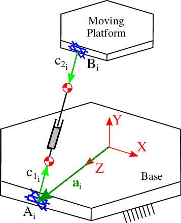
Accordingto Fig. 3, the position of the center of mass (CM) of the cylinder and the piston of each limb may be written as:
 \begin{align} \boldsymbol{{c}}_{1_i} =\boldsymbol{{a}}_i+ c_{1_i} \hat{\boldsymbol{{s}}}_i, \end{align}
 \begin{align} \boldsymbol{{c}}_{2_i}= \boldsymbol{{a}}_i+ \left( \ell_i - c_{2_i} \right) \hat{\boldsymbol{{s}}}_i. \end{align}
CM position of each cylinder and piston.

3. Velocity Analysis
By time derivative of both sides of Eq. (1), the velocity loop closure is obtained as:
 \begin{equation} \dot{\boldsymbol{{x}}}= \dot{\ell}_i \hat{\boldsymbol{{s}}}_i + \ell_i \left(\boldsymbol{\omega}_i \times \hat{\boldsymbol{{s}}}_i \right),\end{equation}
in which
 $\dot{\ell}_i$
is the rate of limb length elongation and
 $\boldsymbol{\omega}_i$
is the angular velocity of each limb. In order to extract
 $\dot{\ell}_i$
, dot multiply both sides of Eq. (6) by
 $\hat{\boldsymbol{{s}}}_i$
:
 \begin{equation} \dot{\ell}_i={\hat{\boldsymbol{{s}}}_i}{}^{T} \dot{\boldsymbol{{x}}}.\end{equation}
Thus, the input-output Jacobian matrix of the 3-UPU TPM may be formulated as:
 \begin{equation} \boldsymbol{{J}}= \left[{\hat{\boldsymbol{{s}}}_1} , {\hat{\boldsymbol{{s}}}_2} , {\hat{\boldsymbol{{s}}}_3}\right] ^{T}.\end{equation}
3.1 Angular velocity
In a similar way, by cross-multiplying both sides of Eq. (6) by
 $\hat{\boldsymbol{{s}}}_i$
, the perpendicular term of angular velocity of each limb will be derived as follows:
 \begin{equation}\boldsymbol{\omega}_{{\bot_i}}= \frac{ \hat{\boldsymbol{{s}}}_{{i}_\times}}{\ell_i} \dot{\boldsymbol{{x}}},\end{equation}
in which
 $\hat{\boldsymbol{{s}}}_{{i}_\times}$
represent
 $3\times 3$
skew-symmetric matrix generated from vector
 $\hat{\boldsymbol{{s}}}_i$
. It should be noted that
 $\boldsymbol{\omega}_{\bot_i} \neq \boldsymbol{\omega}_{i}$
, and this is one of the common mistakes in the literature on the dynamic analysis of parallel robots with universal joints and has been carefully examined in refs. [Reference Carricato and Gosselin32, Reference Vakil, Pendar and Zohoor33]. Consequently, two elements of the angular velocity of each limb may be presented as
 $\boldsymbol{\omega}_{\bot_i}$
, which is normal to the limb axis, and
 $\omega_{s_i} $
, that is in the direction of the limb axis, as the following:
 \begin{equation} \boldsymbol{\omega}_i=\boldsymbol{\omega}_{\bot_i}+ \omega_{s_i} \hat{\boldsymbol{{s}}}_i= \boldsymbol{{J}}_{\omega_i} \dot{\boldsymbol{{x}}}.\end{equation}
Now, in order to extract
 $\omega_{s_i}$
, according to Fig. 2,
 $\boldsymbol{\omega}_i$
may be decomposed into two components along the unit vectors of
 $\hat{\boldsymbol{{u}}}_i$
and
 $\hat{\boldsymbol{{v}}}_i$
of the universal joint as follows:
 \begin{equation} \boldsymbol{\omega}_i= \omega_{u_i} \hat{\boldsymbol{{u}}}_i + \omega_{v_i} \hat{\boldsymbol{{v}}}_i.\end{equation}
Since each limb’s angular velocity is placed on the
 $\hat{\boldsymbol{{u}}}_i-\hat{\boldsymbol{{v}}}_i$
plane, the relationship of
 $ \hat{\boldsymbol{{w}}}_i \cdot \boldsymbol{\omega}_i =0$
may be established. Hence, by dot multiplying both sides of Eq. (10) by
 $\hat{\boldsymbol{{w}}}_i$
, the scalar value of
 $\omega_{s_i}$
would be derived as:
 \begin{equation} \omega_{s_i}= \frac{ - \hat{\boldsymbol{{w}}}_i \cdot \boldsymbol{\omega}_{\bot_i} } { \hat{\boldsymbol{{w}}}_i \cdot \hat{\boldsymbol{{s}}}_i },\end{equation}
where
 $\boldsymbol{\omega}_{{\bot_i}}$
was previously defined in Eq. (9). Now, by rewriting Eq. (10) as a function of
 $\dot{\boldsymbol{{x}}}$
,
 $\boldsymbol{{J}}_{\omega_i}$
may be derived as follows:
 \begin{equation} \boldsymbol{{J}}_{\omega_i}= \boldsymbol{{J}}_{\omega_{\bot_i}} + \hat{\boldsymbol{{s}}}_i \; \boldsymbol{\mathcal{J}}_{\omega_{s_i}},\end{equation}
in which
 $ \;\boldsymbol{{J}}_{\omega_{\bot_i}}$
and
 $\boldsymbol{\mathcal{J}}_{\omega_{s_i}}$
are defined as:
 \begin{align} \boldsymbol{{J}}_{\omega_{\bot_i}} = \frac{\hat{\boldsymbol{{s}}}_{i_\times}} {\ell_i}\;\;,\;\; \in \mathbb{ R}^{3\times 3} , \end{align}
 \begin{align} \boldsymbol{\mathcal{J}}_{\omega_{s_i}} = \left(\frac{-{\hat{\boldsymbol{{w}}}_i}{}^T} {\hat{\boldsymbol{{w}}}_i \cdot \hat{\boldsymbol{{s}}}_i }\right) \boldsymbol{{J}}_{\omega_{\bot_i}} \;\;,\;\; \in \mathbb{ R}^{1\times 3}. \end{align}
In order to derive scalar values of
 $\omega_{u_i}$
and
 $\omega_{v_i}$
, substitution of (11) into (6) and dot multiplying both sides by
 $\hat{\boldsymbol{{v}}}_i$
and
 $\hat{\boldsymbol{{u}}}_i$
, respectively, results in:
 \begin{align} \omega_{u_i} = \frac{\hat{\boldsymbol{{v}}}_i \cdot \dot{\boldsymbol{{x}}}- \hat{\boldsymbol{{v}}}_i \cdot \hat{\boldsymbol{{s}}}_i \; \dot{\ell}_i }{ \ell_i \; \hat{\boldsymbol{{v}}}_i \cdot \left( \hat{\boldsymbol{{u}}}_i \times \hat{\boldsymbol{{s}}}_i \right) }, \end{align}
 \begin{align} \omega_{v_i}= \frac{\hat{\boldsymbol{{u}}}_i \cdot \dot{\boldsymbol{{x}}}- \hat{\boldsymbol{{u}}}_i \cdot \hat{\boldsymbol{{s}}}_i \; \dot{\ell}_i }{ \ell_i \; \hat{\boldsymbol{{u}}}_i \cdot \left( \hat{\boldsymbol{{v}}}_i \times \hat{\boldsymbol{{s}}}_i \right) }. \end{align}
Substitution properties
 $\hat{\boldsymbol{{v}}}_i\cdot \left( \hat{\boldsymbol{{u}}}_i \times \hat{\boldsymbol{{s}}}_i \right)=-\hat{\boldsymbol{{s}}}_i \cdot \left( \hat{\boldsymbol{{u}}}_i \times \hat{\boldsymbol{{v}}}_i \right)$
,
 $\hat{\boldsymbol{{u}}}_i \cdot \left( \hat{\boldsymbol{{v}}}_i \times \hat{\boldsymbol{{s}}}_i \right)=\hat{\boldsymbol{{s}}}_i \cdot \left( \hat{\boldsymbol{{u}}}_i \times \hat{\boldsymbol{{v}}}_i \right)$
, and
 $\left( \hat{\boldsymbol{{u}}}_i \times \hat{\boldsymbol{{v}}}_i \right)=\hat{\boldsymbol{{w}}}_i$
in (15) result in:
 \begin{align} \omega_{u_i} = -\left( \frac{\hat{\boldsymbol{{v}}}_i \cdot \dot{\boldsymbol{{x}}}- \hat{\boldsymbol{{v}}}_i \cdot \hat{\boldsymbol{{s}}}_i \; \dot{\ell}_i }{ \ell_i \hat{\boldsymbol{{s}}}_i \cdot \hat{\boldsymbol{{w}}}_i } \right)= \boldsymbol{\mathcal{J}}_{\omega_{u_i}} \dot{\boldsymbol{{x}}} , \end{align}
 \begin{align} \omega_{v_i}= +\left( \frac{\hat{\boldsymbol{{u}}}_i \cdot \dot{\boldsymbol{{x}}}- \hat{\boldsymbol{{u}}}_i \cdot \hat{\boldsymbol{{s}}}_i \; \dot{\ell}_i }{ \ell_i \hat{\boldsymbol{{s}}}_i \cdot \hat{\boldsymbol{{w}}}_i } \right)= \boldsymbol{\mathcal{J}}_{\omega_{v_i}} \dot{\boldsymbol{{x}}}. \end{align}
On the other hand,
 $\boldsymbol{\mathcal{J}}_{\omega_{u_i}}$
and
 $\boldsymbol{\mathcal{J}}_{\omega_{v_i}}$
may be derived by the substitution of
 $\dot{\ell}_i= {\hat{\boldsymbol{{s}}}_i}{}^T \dot{\boldsymbol{{x}}} $
into (16) and some manipulations, as follows:
 \begin{align} \boldsymbol{\mathcal{J}}_{\omega_{u_i}} = \frac{{\hat{\boldsymbol{{v}}}_i}{}^T \left(- \boldsymbol{{I}}_{3\times 3} + \hat{\boldsymbol{{s}}}_i {\hat{\boldsymbol{{s}}}_i}{}^T \right) }{ \ell_i \hat{\boldsymbol{{s}}}_i \cdot \hat{\boldsymbol{{w}}}_i }\;\;,\;\; \in \mathbb{ R}^{1\times 3} , \end{align}
 \begin{align} \boldsymbol{\mathcal{J}}_{\omega_{v_i}}= \frac{{\hat{\boldsymbol{{u}}}_i}{}^T \left(+ \boldsymbol{{I}}_{3\times 3} - \hat{\boldsymbol{{s}}}_i {\hat{\boldsymbol{{s}}}_i}{}^T \right) }{ \ell_i \hat{\boldsymbol{{s}}}_i \cdot \hat{\boldsymbol{{w}}}_i }\;\;,\;\; \in \mathbb{ R}^{1\times 3}. \end{align}
in which,
 $\boldsymbol{{I}}_{3 \times 3}$
denotes
 $3 \times 3$
identity matrix.
3.2 Linear velocity
Bytime derivative of both sides of Eq. (5), the linear velocity of the CM of the cylinder and the piston of each limb may be derived as:
 \begin{align} \boldsymbol{{v}}_{c_{1_i}}=c_{1_i} \left(\boldsymbol{\omega}_i \times \hat{\boldsymbol{{s}}}_i\right), \end{align}
 \begin{align} \boldsymbol{{v}}_{c_{2_i}}=(\ell_i-c_{2_i}) \left(\boldsymbol{\omega}_i \times \hat{\boldsymbol{{s}}}_i\right)+\dot{\ell}_i \hat{\boldsymbol{{s}}}_{i}. \end{align}
Using equations (7) and (10), and anti-commutative property of cross-product, these linear velocities may be written as a function of
 $\dot{\boldsymbol{{x}}}$
as follow:
 \begin{align} \boldsymbol{{v}}_{c_{1_i}}=-c_{1_i} \hat{\boldsymbol{{s}}}_{i_\times} \boldsymbol{\omega}_i= \left( -c_{1_i} \hat{\boldsymbol{{s}}}_{i_\times} \;\boldsymbol{{J}}_{\omega_i} \right)\dot{\boldsymbol{{x}}}, \end{align}
 \begin{align} \boldsymbol{{v}}_{c_{2_i}}= -\left( \left(\ell_i-c_{2_i}\right) \hat{\boldsymbol{{s}}}_{i_\times} \;\boldsymbol{{J}}_{\omega_i} \right)\dot{\boldsymbol{{x}}}+\left( {\hat{\boldsymbol{{s}}}_i} {\hat{\boldsymbol{{s}}}_i}{}^T \right) \dot{\boldsymbol{{x}}}. \end{align}
Therefore, the linear Jacobians of each limb may be derived as follows:
 \begin{align} \boldsymbol{{J}}_{v_{1_i}}= -c_{1_i} \hat{\boldsymbol{{s}}}_{i_\times} \;\boldsymbol{{J}}_{\omega_i}, \end{align}
 \begin{align} \boldsymbol{{J}}_{v_{2_i}}= - \left(\ell_i-c_{2_i}\right) \hat{\boldsymbol{{s}}}_{i_\times} \;\boldsymbol{{J}}_{\omega_i} + {\hat{\boldsymbol{{s}}}_i} {\hat{\boldsymbol{{s}}}_i}{}^T. \end{align}
Finally, general Jacobian matrix of each limb can be written as
 $\boldsymbol{{J}}_{1_i}=\left[ {\boldsymbol{{J}}_{v_{1_i}}}^T, {\boldsymbol{{J}}_{\omega_i}}^T \right]^T$
and
 $\boldsymbol{{J}}_{2_i}=\left[ {\boldsymbol{{J}}_{v_{2_i}}}^T, {\boldsymbol{{J}}_{\omega_i}}^T\right]^T$
.
4. Acceleration Analysis
In order to derive
 $\ddot{\ell}_i$
, we take the time derivative of Eq. (7) as follows:
 \begin{equation} \ddot{\ell}_i={\hat{\boldsymbol{{s}}}_i}{}^T \ddot{\boldsymbol{{x}}}+({\boldsymbol{\omega}_i \times \hat{\boldsymbol{{s}}}_i})^T \dot{\boldsymbol{{x}}}.\end{equation}
Thus, it is obvious that
 $\;\dot{\boldsymbol{{\!J}}}$
may be derived as:
 $\dot{\boldsymbol{{J}}}=\left[\left({\boldsymbol{\omega}_1 \times \hat{\boldsymbol{{s}}}_1}\right) , \left({\boldsymbol{\omega}_2 \times \hat{\boldsymbol{{s}}}_2} \right) , \left({\boldsymbol{\omega}_3 \times\hat{\boldsymbol{{s}}}_3}\right)\right]^T$
. Moreover, by time derivative on both sides of Eq. (6), acceleration loop closure equation can be derived for each loop as:
 \begin{equation} \ddot{\boldsymbol{{x}}}= \ddot{\ell}_i \hat{\boldsymbol{{s}}}_i + 2\dot{\ell}_i \left(\boldsymbol{\omega}_i \times {\hat{\boldsymbol{{s}}}_i} \right) + \ell_i \left(\dot{\boldsymbol{\omega}}_i \times {\hat{\boldsymbol{{s}}}_i} \right)+ \ell_i \left(\boldsymbol{\omega}_i \times \left(\boldsymbol{\omega}_i \times {\hat{\boldsymbol{{s}}}_i} \right) \right).\end{equation}
4.1 Angular acceleration
In order to derive
 $\dot{\boldsymbol{\omega}}_{\bot_i} $
, one should cross-multiply both sides of the Eq. (22) by
 $\hat{\boldsymbol{{s}}}_i$
, which results in:
 \begin{equation}\dot{\boldsymbol{\omega}}_{\bot_i} = \frac{ \hat{\boldsymbol{{s}}}_i \times \left(\ddot{\boldsymbol{{x}}}- 2\dot{\ell}_i \left(\boldsymbol{\omega}_i \times {\hat{\boldsymbol{{s}}}_i} \right)- \ell_i \left(\boldsymbol{\omega}_i \times \left(\boldsymbol{\omega}_i \times {\hat{\boldsymbol{{s}}}_i} \right) \right) \right)}{\ell_i}= \boldsymbol{{J}}_{\omega_{\bot_i}} \ddot{\boldsymbol{{x}}} + \dot{\boldsymbol{{J}}}_{\omega_{\bot_i}} \dot{\boldsymbol{{x}}}.\end{equation}
Using anti-commutative property of cross-product and Eq. (10),
 $\dot{\boldsymbol{{J}}}_{\omega_{\bot_i}}$
may be derived as follow:
 \begin{equation} \dot{\boldsymbol{{J}}}_{\omega_{\bot_i}}=\frac{ 2 \;\dot{\ell}_i\; {\hat{\boldsymbol{{s}}}_{i_\times}}{}^2 \;\boldsymbol{{J}}_{\omega_i} +\ell_i \;\hat{\boldsymbol{{s}}}_{i_\times} \boldsymbol{\omega}_{i_{\times}} \hat{\boldsymbol{{s}}}_{i_\times} \boldsymbol{{J}}_{\omega_i}}{\ell_i}.\end{equation}
To calculate
 $\dot \omega_{u_i}$
and
 $\dot \omega_{s_i}$
scalar values, time derivative of equations of (10) and (11) will result in:
 \begin{align} \dot{\boldsymbol{\omega}}_i=\dot{\boldsymbol{\omega}}_{\bot_i}+ \dot \omega_{s_i} \hat{\boldsymbol{{s}}}_i= \boldsymbol{{J}}_{\omega_i} \ddot{\boldsymbol{{x}}} + \dot{\boldsymbol{{J}}}_{\omega_i} \dot{\boldsymbol{{x}}}, \end{align}
 \begin{align} \dot{\boldsymbol{\omega}}_i= \dot \omega_{u_i} \hat{\boldsymbol{{u}}}_i + \dot \omega_{v_i} \hat{\boldsymbol{{v}}}_i+ \omega_{u_i} \omega_{v_i} \hat{\boldsymbol{{w}}}_i. \end{align}
Now, noting that
 $\hat{\boldsymbol{{v}}}_i \cdot \hat{\boldsymbol{{s}}}_i=0$
,
 $\dot \omega_{u_i}$
and
 $\dot \omega_{s_i}$
can be calculated by equating (25a) and (25b), and applying dot product with
 $\hat{\boldsymbol{{u}}}_i$
and
 $\hat{\boldsymbol{{s}}}_i$
, respectively, as follows:
 \begin{align} \dot \omega_{u_i}= \left(\dot{\boldsymbol{\omega}}_{\bot_i}+ \dot \omega_{s_i} \hat{\boldsymbol{{s}}}_i \right) \cdot \hat{\boldsymbol{{u}}}_i , \end{align}
 \begin{align} \dot{\omega}_{s_i}= \dot \omega_{u_i} \left( \hat{\boldsymbol{{u}}}_i \cdot \hat{\boldsymbol{{s}}}_i \right) + \omega_{u_i} \omega_{v_i} \left(\hat{\boldsymbol{{w}}}_i \cdot \hat{\boldsymbol{{s}}}_i \right). \end{align}
Now,
 $\dot \omega_{s_i}$
would be derived explicitly by substituting (26a) into (26b), as follows:
 \begin{equation}\dot{\omega}_{s_i}= \frac{ \left(\dot{\boldsymbol{\omega}}_{\bot_i} \cdot \hat{\boldsymbol{{u}}}_i\right) \left( \hat{\boldsymbol{{u}}}_i \cdot \hat{\boldsymbol{{s}}}_i \right)+ \omega_{u_i} \omega_{v_i} \left(\hat{\boldsymbol{{w}}}_i \cdot \hat{\boldsymbol{{s}}}_i \right) }{1-\left( \hat{\boldsymbol{{u}}}_i \cdot \hat{\boldsymbol{{s}}}_i \right)^2}.\end{equation}
On the other hand,
 $\dot{\omega}_{s_i}=\boldsymbol{\mathcal{J}}_{\omega_{s_i}} \ddot{\boldsymbol{{x}}}+ \dot{ \boldsymbol{\mathcal{J}}}_{\omega_{s_i}} \dot{\boldsymbol{{x}}}$
is another type of representation of Eq. (27). Now, to derive
 $\boldsymbol{\mathcal{J}}_{\omega_{s_i}}$
and
 $\dot{\boldsymbol{\mathcal{J}}}_{\omega_{s_i}}$
, by the substitution of equations (16) and (23) into Eq. (27) and by some manipulations,
 $\dot{\omega}_{s_i}$
should be written as follows:
 \begin{equation}\dot{\omega}_{s_i}= \frac{ \left( \hat{\boldsymbol{{u}}}_i \cdot \hat{\boldsymbol{{s}}}_i \right) {\hat{\boldsymbol{{u}}}_i}{}^T \left( \boldsymbol{{J}}_{\omega_{\bot_i}} \ddot{\boldsymbol{{x}}} + \dot{\boldsymbol{{J}}}_{\omega_{\bot_i}} \ddot{\boldsymbol{{x}}} \right)+ \left(\hat{\boldsymbol{{w}}}_i \cdot \hat{\boldsymbol{{s}}}_i \right) \left( \boldsymbol{\mathcal{J}}_{\omega_{u_i}} \dot{\boldsymbol{{x}}} \;\boldsymbol{\mathcal{J}}_{\omega_{v_i}} \dot{\boldsymbol{{x}}} \right) }{1-\left( \hat{\boldsymbol{{u}}}_i \cdot \hat{\boldsymbol{{s}}}_i \right)^2}= \boldsymbol{\mathcal{J}}_{\omega_{s_i}} \ddot{\boldsymbol{{x}}} + \dot{\boldsymbol{\mathcal{J}}}_{\omega_{s_i}} \dot{\boldsymbol{{x}}}.\end{equation}
Therefore,
 $\boldsymbol{\mathcal{J}}_{\omega_{s_i}}$
and
 $\dot{\boldsymbol{\mathcal{J}}}_{\omega_{s_i}}$
may be derived as:
 \begin{align} \boldsymbol{\mathcal{J}}_{\omega_{s_i}}= \frac{ \left( \hat{\boldsymbol{{u}}}_i \cdot \hat{\boldsymbol{{s}}}_i \right) {\hat{\boldsymbol{{u}}}_i}{}^T }{1-\left( \hat{\boldsymbol{{u}}}_i \cdot \hat{\boldsymbol{{s}}}_i \right)^2} \;\boldsymbol{{J}}_{\omega_{\bot_i}}, \end{align}
 \begin{align} \dot{\boldsymbol{\mathcal{J}}}_{\omega_{s_i}}= \frac{ \left( \hat{\boldsymbol{{u}}}_i \cdot \hat{\boldsymbol{{s}}}_i \right) {\hat{\boldsymbol{{u}}}_i}{}^T \dot{\boldsymbol{{J}}}_{\omega_{\bot_i}} + \left(\hat{\boldsymbol{{w}}}_i \cdot \hat{\boldsymbol{{s}}}_i \right) \left( \boldsymbol{\mathcal{J}}_{\omega_{u_i}} \dot{\boldsymbol{{x}}} \;\boldsymbol{\mathcal{J}}_{\omega_{v_i}} \right) }{1-\left( \hat{\boldsymbol{{u}}}_i \cdot \hat{\boldsymbol{{s}}}_i \right)^2}. \end{align}
It should be noted that
 $\boldsymbol{\mathcal{J}}_{\omega_{s_i}}$
can be derived from both (14b) and (29a) equations, and the equality of these two equations is easily proveable. Eventually, by rewriting Eq. (25) as
 $\dot{\boldsymbol{\omega}}_i= \boldsymbol{{J}}_{\omega_i} \ddot{\boldsymbol{{x}}} + \dot{\boldsymbol{{J}}}_{\omega_i} \dot{\boldsymbol{{x}}}$
, in which
 $\boldsymbol{{J}}_{\omega_i}$
is shown in Eq. (13),
 $\dot{\boldsymbol{{J}}}_{\omega_i}$
may be derived as:
 \begin{equation} \dot{\boldsymbol{{J}}}_{\omega_i}=\dot{\boldsymbol{{J}}}_{\omega_{\bot_i}} + \hat{\boldsymbol{{s}}}_i \; \dot{\boldsymbol{\mathcal{J}}}_{\omega_{s_i}},\end{equation}
where, Eq. (24) and (29b) define
 $\dot{\boldsymbol{{J}}}_{\omega_{\bot_i}}$
and
 $\dot{\boldsymbol{\mathcal{J}}}_{\omega_{s_i}}$
, respectively.
4.2 Linear acceleration
By differentiation of Eq. (18), the acceleration vectors of the piston and the cylinder CM may bederived as:
 \begin{align} \boldsymbol{{a}}_{c_{1_i}}=c_{1_i}\left(\dot{\boldsymbol{\omega}}_i \times \hat{\boldsymbol{{s}}}_i + \boldsymbol{\omega}_i \times (\boldsymbol{\omega}_i \times \hat{\boldsymbol{{s}}}_i)\right) = \boldsymbol{{J}}_{v_{1_i}}\ddot{\boldsymbol{{x}}}+ \dot{\boldsymbol{{J}}}_{v_{1_i}} \dot{\boldsymbol{{x}}}, \end{align}
 \begin{align} \boldsymbol{{a}}_{c_{2_i}}=(\ell_i-c_{2_i}) \left(\dot{\boldsymbol{\omega}}_i \times \hat{\boldsymbol{{s}}}_i + \boldsymbol{\omega}_i \times (\boldsymbol{\omega}_i \times \hat{\boldsymbol{{s}}}_i) \right)+2 \dot{\ell}_i (\boldsymbol{\omega}_i \times \hat{\boldsymbol{{s}}}_i)+\ddot{\ell}_i \hat{\boldsymbol{{s}}}_i = \boldsymbol{{J}}_{v_{2_i}}\ddot{\boldsymbol{{x}}}+ \dot{\boldsymbol{{J}}}_{v_{2_i}} \dot{\boldsymbol{{x}}}. \end{align}
Using anti-commutative property of cross-product, and equations (10), (21) and (25a), different terms of Eq. (31) can be written as a function of
 $\dot{\boldsymbol{{x}}}$
and
 $\ddot{\boldsymbol{{x}}}$
as follows:
 \begin{align} \dot{\boldsymbol{\omega}}_i \times \hat{\boldsymbol{{s}}}_i = - \hat{\boldsymbol{{s}}}_{i_\times} \left(\boldsymbol{{J}}_{\omega_i} \ddot{\boldsymbol{{x}}} + \dot{\boldsymbol{{J}}}_{\omega_i} \dot{\boldsymbol{{x}}} \right), \end{align}
 \begin{align} \boldsymbol{\omega}_i \times (\boldsymbol{\omega}_i \times \hat{\boldsymbol{{s}}}_i)=-\boldsymbol{\omega}_{i_{\times}}\; \hat{\boldsymbol{{s}}}_{i_\times} \; \boldsymbol{\omega}_i= -\boldsymbol{\omega}_{i_{\times}} \;\hat{\boldsymbol{{s}}}_{i_\times}\; \left(\boldsymbol{{J}}_{\omega_i} \dot{\boldsymbol{{x}}} \right), \end{align}
 \begin{align} 2 \dot{\ell}_i (\boldsymbol{\omega}_i \times \hat{\boldsymbol{{s}}}_i)= -2 \dot{\ell}_i \hat{\boldsymbol{{s}}}_{i_\times} \;\left(\boldsymbol{{J}}_{\omega_i} \dot{\boldsymbol{{x}}} \right), \end{align}
 \begin{align} \hat{\boldsymbol{{s}}}_i \ddot{\ell}_i = \hat{\boldsymbol{{s}}}_i \left( {\hat{\boldsymbol{{s}}}_i}{}^T \ddot{\boldsymbol{{x}}} + \left(\boldsymbol{\omega}_i \times \hat{\boldsymbol{{s}}}_i \right)^T \dot{\boldsymbol{{x}}} \right). \end{align}
Therefore, Eq. (31) can be rewritten as follows:
 \begin{equation} \boldsymbol{{a}}_{c_{1_i}}=- \left( c_{1_i} \hat{\boldsymbol{{s}}}_{i_\times} \boldsymbol{{J}}_{\omega_i} \right) \ddot{\boldsymbol{{x}}} - c_{1_i} \left( \hat{\boldsymbol{{s}}}_{i_\times} \dot{\boldsymbol{{J}}}_{\omega_i} + \boldsymbol{\omega}_{i_{\times}}\; \hat{\boldsymbol{{s}}}_{i_\times}\; \boldsymbol{{J}}_{\omega_i} \right) \dot{\boldsymbol{{x}}} = \boldsymbol{{J}}_{v_{1_i}}\ddot{\boldsymbol{{x}}}+ \dot{\boldsymbol{{J}}}_{v_{1_i}} \dot{\boldsymbol{{x}}},\end{equation}
 \begin{equation}\begin{split} \boldsymbol{{a}}_{c_{2_i}}= & \left( -(\ell_i-c_{2_i}) \hat{\boldsymbol{{s}}}_{i_\times} \; \boldsymbol{{J}}_{\omega_i} + \hat{\boldsymbol{{s}}}_i {\hat{\boldsymbol{{s}}}_i}{}^T \right ) \ddot{\boldsymbol{{x}}} + \\& \left( - (\ell_i-c_{2_i}) \left( \hat{\boldsymbol{{s}}}_{i_\times}\;\dot{\boldsymbol{{J}}}_{\omega_i} +\boldsymbol{\omega}_{i_{\times}}\; \hat{\boldsymbol{{s}}}_{i_\times}\; \boldsymbol{{J}}_{\omega_i} \right) -2 \dot{\ell}_i \hat{\boldsymbol{{s}}}_{i_\times} \;\boldsymbol{{J}}_{\omega_i} + \hat{\boldsymbol{{s}}}_i \left(\boldsymbol{\omega}_i \times \hat{\boldsymbol{{s}}}_i \right)^T \right) \dot{\boldsymbol{{x}}} = \boldsymbol{{J}}_{v_{2_i}}\ddot{\boldsymbol{{x}}}+ \dot{\boldsymbol{{J}}}_{v_{2_i}} \dot{\boldsymbol{{x}}}.\end{split}\end{equation}
It should be noted that
 $\boldsymbol{{J}}_{v_{1_i}}$
and
 $\boldsymbol{{J}}_{v_{2_i}}$
are similar to Eq. (20), and
 $\dot{\boldsymbol{{J}}}_{v_{1_i}}$
and
 $\dot{\boldsymbol{{J}}}_{v_{2_i}}$
may be derived as:
 \begin{align} \dot{\boldsymbol{{J}}}_{v_{1_i}}=- c_{1_i} \left( \hat{\boldsymbol{{s}}}_{i_\times}\;\dot{\boldsymbol{{J}}}_{\omega_i} +\boldsymbol{\omega}_{i_{\times}}\; \hat{\boldsymbol{{s}}}_{i_\times}\; \boldsymbol{{J}}_{\omega_i} \right), \end{align}
 \begin{align} \dot{\boldsymbol{{J}}}_{v_{2_i}}= - (\ell_i-c_{2_i}) \left( \hat{\boldsymbol{{s}}}_{i_\times}\;\dot{\boldsymbol{{J}}}_{\omega_i} +\boldsymbol{\omega}_{i_{\times}}\; \hat{\boldsymbol{{s}}}_{i_\times}\; \boldsymbol{{J}}_{\omega_i} \right) -2 \dot{\ell}_i \hat{\boldsymbol{{s}}}_{i_\times} \;\boldsymbol{{J}}_{\omega_i} + \hat{\boldsymbol{{s}}}_i \left(\boldsymbol{\omega}_i \times \hat{\boldsymbol{{s}}}_i \right)^T. \end{align}
5. Dynamic Analysis
In this section, the extraction of 3-UPU TPM dynamics using the principle of virtual work is first examined. Then, explicit dynamics are derived and its properties are proved.
5.1 Implicit analysis
It can be proved that the inverse dynamics of the 3-UPU TPM, using the principle of virtual work, can be derived as follows [Reference Tsai22]:
 \begin{equation} \boldsymbol{{J}}^{T} \tau + \boldsymbol{{f}}_p+ \sum_{i=1}^{3} \left( {\boldsymbol{{J}}_{{1_i}}}^{T} \boldsymbol{{f}}_{1_i} + {\boldsymbol{{J}}_{{2_i}}}^{T} \boldsymbol{{f}}_{2_i} \right) =0,\end{equation}
in which,
 $\boldsymbol{{J}}$
is the Jacobian matrix of the whole manipulator,
 $\boldsymbol{\tau}$
is the actuator generalized forces, and
 ${\boldsymbol{{J}}_{{1_i}}}$
and
 ${\boldsymbol{{J}}_{{2_i}}}$
represent the general Jacobian matrix of the cylinder and piston of each limb. Furthermore,
 $\boldsymbol{{f}}_p$
and
 $\boldsymbol{{f}}_i$
represent the inertia forces exerted at the CM of the cylinder and piston of each limb. By neglecting the friction terms and considering that in 3-UPU TPM the moving platform has no rotational motion, these inertial forces can be derived as follows [Reference Zhao and Gao34]:
 \begin{align} \boldsymbol{{f}}_p =- m_p\left(\ddot{\boldsymbol{{x}}}-\boldsymbol{{g}}_0 \right) + \boldsymbol{{f}}_{d}, \end{align}
 \begin{align} \boldsymbol{{f}}_{1_i} =-\begin{bmatrix} m_{1_i}\left(\boldsymbol{{a}}_{c_{1_i}}-\boldsymbol{{g}}_0 \right) \\ ^{0}\mathrm{\boldsymbol{{I}}}_{1_i} \; \dot{\boldsymbol{\omega}}_{i} +\boldsymbol{\omega}_{i} \times \left(^{0}\mathrm{\boldsymbol{{I}}}_{1_i}\;\boldsymbol{\omega}_{i} \right ) \end{bmatrix}, \end{align}
 \begin{align} \boldsymbol{{f}}_{2_i} =-\begin{bmatrix} m_{2_i}\left(\boldsymbol{{a}}_{c_{2_i}}-\boldsymbol{{g}}_0 \right) \\ ^{0}\mathrm{\boldsymbol{{I}}}_{2_i} \; \dot{\boldsymbol{\omega}}_{i} +\boldsymbol{\omega}_{i} \times \left(^{0}\mathrm{\boldsymbol{{I}}}_{2_i}\;\boldsymbol{\omega}_{i} \right ) \end{bmatrix}. \end{align}
in which
 ${}^{0}\mathrm{\boldsymbol{{I}}}_{1_i}$
and
 ${}^{0}\mathrm{\boldsymbol{{I}}}_{2_i}$
denote the moment of inertia of the cylinder and piston of each limb, about the CM frame with respect to the base coordinate system. Moreover,
 $\boldsymbol{{f}}_d$
indicates the external disturbance wrench applied to the moving platform CM. Therefore, the inverse dynamic model of 3-UPU TPM can be formulated as:
 \begin{equation} \boldsymbol{{J}}^{T} \tau =\boldsymbol{{f}}= -\left(\boldsymbol{{f}}_p+ \sum_{i=1}^{3} \left({\boldsymbol{{J}}_{{1_i}}}^{T} \boldsymbol{{f}}_{1_i} + {\boldsymbol{{J}}_{{2_i}}}^{T} \boldsymbol{{f}}_{2_i}\right) \right),\end{equation}
where
 $\boldsymbol{{f}}= \boldsymbol{{J}}^{T} \tau$
represent projection of the actuator forces
 $\boldsymbol{\tau}$
, on the moving platform. Equation (38) represents the implicit dynamic formulation of the 3-UPU TPM. According to this equation, actuator forces,
 $\boldsymbol{\tau}$
could be uniquely obtained by
 $\boldsymbol{\tau}=\boldsymbol{{J}}^{-T}\boldsymbol{{f}}$
at non-singular configurations of robot.
5.2 Explicit dynamics
In order to derive the explicit form of dynamic formulations adopting the principle of virtual work, implicit dynamic equation (38) is reconsidered. In Section 3, it was shown that the velocity and acceleration of the CM of the cylinder and piston of each limb can be extracted as follows:
 \begin{align} \boldsymbol{{v}}_{c_{1_i}} =\boldsymbol{{J}}_{v_{1_i}} \dot{\boldsymbol{{x}}}\;\;,\;\; \boldsymbol{{v}}_{c_{2_i}} =\boldsymbol{{J}}_{v_{2_i}} \dot{\boldsymbol{{x}}} \;\;, \;\; \boldsymbol{{a}}_{c_{1_i}} =\boldsymbol{{J}}_{v_{1_i}} \ddot{\boldsymbol{{x}}}+ \dot{\boldsymbol{{J}}}_{v_{1_i}} \dot{\boldsymbol{{x}}} \;\;,\;\;\boldsymbol{{a}}_{c_{2_i}}= \boldsymbol{{J}}_{v_{2_i}} \ddot{\boldsymbol{{x}}}+ \dot{\boldsymbol{{J}}}_{v_{2_i}} \dot{\boldsymbol{{x}}}, \end{align}
 \begin{align} \boldsymbol{\omega}_i= \boldsymbol{{J}}_{\omega_i} \dot{\boldsymbol{{x}}} \;\;, \;\; \dot \omega_i= \boldsymbol{{J}}_{\omega_i} \ddot{\boldsymbol{{x}}} + \dot{\boldsymbol{{J}}}_{\omega_i} \dot{\boldsymbol{{x}}}. \end{align}
Substitute Eq. (39) in Eq. (37) results in:
 \begin{align} \boldsymbol{{f}}_{p}=- m_p\left(\ddot{\boldsymbol{{x}}}-\boldsymbol{{g}}_0\right)+ \boldsymbol{{f}}_d, \end{align}
 \begin{align} \boldsymbol{{f}}_{1_i}=-\begin{bmatrix} m_{1_i} \left( \boldsymbol{{J}}_{v_{1_i}} \ddot{\boldsymbol{{x}}}+\dot{\boldsymbol{{J}}}_{v_{1_i}} \dot{\boldsymbol{{x}}}-\boldsymbol{{g}}_0 \right) \\ ^{0}\mathrm{\boldsymbol{{I}}}_{1_i}\;\left(\boldsymbol{{J}}_{\omega_{i}}\ddot{\boldsymbol{{x}}}+ \dot{\boldsymbol{{J}}}_{\omega_i}\dot{\boldsymbol{{x}}} \right) +\left(\boldsymbol{{J}}_{\omega_i} \dot{\boldsymbol{{x}}}\right)_{\times} \;^{0}\mathrm{\boldsymbol{{I}}}_{1_{i}}\;\boldsymbol{{J}}_{\omega_i} \dot{\boldsymbol{{x}}} \end{bmatrix}, \end{align}
 \begin{align} \boldsymbol{{f}}_{2_i}=-\begin{bmatrix} m_{2_i} \left( \boldsymbol{{J}}_{v_{2_i}} \ddot{\boldsymbol{{x}}}+\dot{\boldsymbol{{J}}}_{v_{2_i}} \dot{\boldsymbol{{x}}}-\boldsymbol{{g}}_0 \right) \\ ^{0}\mathrm{\boldsymbol{{I}}}_{2_i}\;\left(\boldsymbol{{J}}_{\omega_{i}}\ddot{\boldsymbol{{x}}}+ \dot{\boldsymbol{{J}}}_{\omega_i}\dot{\boldsymbol{{x}}} \right) +\left(\boldsymbol{{J}}_{\omega_i} \dot{\boldsymbol{{x}}}\right)_{\times} \;^{0}\mathrm{\boldsymbol{{I}}}_{2_i}\;\boldsymbol{{J}}_{\omega_i} \dot{\boldsymbol{{x}}} \end{bmatrix}. \end{align}
Using inertial forces Eq. (40), Eq. (38) may be rewritten as:
 \begin{equation}\begin{split} \boldsymbol{{J}}^{T} \tau=\boldsymbol{{f}}+\boldsymbol{{f}}_d =&\sum_{i=1}^{3} m_{1_i} {\boldsymbol{{J}}_{v_{1_i}}}^T \left((\boldsymbol{{J}}_{v_{1_i}} \ddot{\boldsymbol{{x}}}+\dot{\boldsymbol{{J}}}_{v_{1_i}} \dot{\boldsymbol{{x}}})-\boldsymbol{{g}}_0\right)+\sum_{i=1}^{3} m_{2_i} {\boldsymbol{{J}}_{v_{2_i}}}^T \left((\boldsymbol{{J}}_{v_{2_i}} \ddot{\boldsymbol{{x}}}+\dot{\boldsymbol{{J}}}_{v_{2_i}} \dot{\boldsymbol{{x}}})-\boldsymbol{{g}}_0\right)+ \\[5pt] & \sum_{i=1}^{3} {\boldsymbol{{J}}_{\omega_i}}^T \left( \left( ^{0}\mathrm{\boldsymbol{{I}}}_{1_i}+ ^{0}\mathrm{\boldsymbol{{I}}}_{2_i} \right )\;(\boldsymbol{{J}}_{\omega_i}\ddot{\boldsymbol{{x}}}+\boldsymbol{{J}}_{\omega_i}\dot{\boldsymbol{{x}}}) +(\boldsymbol{{J}}_{\omega_i} \dot{\boldsymbol{{x}}})_{\times} \;\left( ^{0}\mathrm{\boldsymbol{{I}}}_{1_i}+ ^{0}\mathrm{\boldsymbol{{I}}}_{2_i} \right )\;\boldsymbol{{J}}_{\omega_i}\dot{\boldsymbol{{x}}}\right) + \\ &m_p (\ddot{\boldsymbol{{x}}} -\boldsymbol{{g}}_0).\end{split}\end{equation}
Therefore, explicit dynamic formulation of 3-UPU TPM can be derived as:
 \begin{equation} \boldsymbol{{J}}^{T} \tau =\boldsymbol{{f}}+\boldsymbol{{f}}_d=\boldsymbol{{M}} (\boldsymbol{{x}}) \ddot{\boldsymbol{{x}}} +\boldsymbol{{C}}(\boldsymbol{{x}},\dot{\boldsymbol{{x}}})\dot{\boldsymbol{{x}}}+\boldsymbol{{g}}(\boldsymbol{{x}}),\end{equation}
where
 $\boldsymbol{{M}}(\boldsymbol{{x}})$
,
 $\boldsymbol{{C}}(\boldsymbol{{x}},\dot{\boldsymbol{{x}}})$
and
 $\boldsymbol{{g}}(\boldsymbol{{x}})$
denote the mass matrix, centrifugal, and Coriolis matrix and gravity vector of the robot, respectively, and can be derived as follows:
 \begin{equation} \boldsymbol{{M}}(\boldsymbol{{x}})=m_p+\sum_{i=1}^{3} \left({\boldsymbol{{J}}_{v_{1_i}}}^T\; m_{1_i}\;{\boldsymbol{{J}}_{v_{1_i}}}+{\boldsymbol{{J}}_{v_{2_i}}}^T\; m_{2_i}\;{\boldsymbol{{J}}_{v_{2_i}}}+{\boldsymbol{{J}}_{\omega_i}}^T\;\left( ^{0}\mathrm{\boldsymbol{{I}}}_{1_i}+ ^{0}\mathrm{\boldsymbol{{I}}}_{2_i} \right )\;\boldsymbol{{J}}_{\omega_i}\right),\end{equation}
 \begin{equation}\begin{split} \boldsymbol{{C}}(\boldsymbol{{x}},\dot{\boldsymbol{{x}}})= \sum_{i=1}^{3} & \left( {\boldsymbol{{J}}_{v_{1_i}}}^T\; m_{1_i}\;{\dot{\boldsymbol{{J}}}_{v_{1_i}}}+{\boldsymbol{{J}}_{v_{2_i}}}^T\; m_{2_i}\;{\dot{\boldsymbol{{J}}}_{v_{2_i}}}+{\boldsymbol{{J}}_{\omega_i}}^T\;\left( ^{0}\mathrm{\boldsymbol{{I}}}_{1_i}+ ^{0}\mathrm{\boldsymbol{{I}}}_{2_i} \right )\;\dot{\boldsymbol{{J}}}_{\omega_i}+ \cdot \cdot \cdot \right .\\[5pt] & \left. {\boldsymbol{{J}}_{\omega_i}}^T\;(\boldsymbol{{J}}_{\omega_i} \dot{\boldsymbol{{x}}})_{\times} \;\left( ^{0}\mathrm{\boldsymbol{{I}}}_{1_i}+ ^{0}\mathrm{\boldsymbol{{I}}}_{2_i} \right )\;\boldsymbol{{J}}_{\omega_i} \right) ,\end{split}\end{equation}
 \begin{equation} \boldsymbol{{g}}(\boldsymbol{{x}})=-m_p\;\boldsymbol{{g}}_0 - \sum_{i=1}^{3} \left( m_{1_i}\; {\boldsymbol{{J}}_{v_{1_i}}}^T + m_{2_i}\; {\boldsymbol{{J}}_{v_{2_i}}}^T \right) \boldsymbol{{g}}_0.\end{equation}
Equation (42) is a multi-input/multi-output (MIMO) nonlinear equation with some advantageous properties for designing model-based controllers as follows [Reference Taghirad21]:
Property 1.
 $\boldsymbol{{M}}(\boldsymbol{{x}})$
is positive definite in all configurations.
Property 2.
 $\left[\dot{\boldsymbol{{M}}}(\boldsymbol{{x}},\dot{\boldsymbol{{x}}})-2\boldsymbol{{C}}(\boldsymbol{{x}},\dot{\boldsymbol{{x}}})\right]$
is skew-symmetric.
The first property may be easily proved, considering the quadratic structure in its formulation. However, to prove the second property, first, the time derivative of
 $\dot{\boldsymbol{{{M}}}}(\boldsymbol{{x}},\dot{\boldsymbol{{x}}})$
may be given as:
 \begin{equation}\begin{split}\dot{\boldsymbol{{M}}}= \;& {\dot{\boldsymbol{{J}}}_{v_{1_i}}}{}^T\; m_{1_i}\;{\boldsymbol{{J}}_{v_{1_i}}}+{\boldsymbol{{J}}_{v_{1_i}}}{}^T\; m_{1_i}\;{\dot{\boldsymbol{{J}}}_{v_{1_i}}}+{\dot{\boldsymbol{{J}}}_{v_{2_i}}}{}^T\; m_{2_i}\;{\boldsymbol{{J}}_{v_{2_i}}}+{\boldsymbol{{J}}_{v_{2_i}}}{}^T\; m_{2_i}\;{\dot{\boldsymbol{{J}}}_{v_{2_i}}}+ {\dot{\boldsymbol{{J}}}_{\omega_i}}{}^T \left(^{0}\mathrm{\boldsymbol{{I}}}_{1_i}+ {^{0}\mathrm{\boldsymbol{{I}}}_{2_i}} \right )\boldsymbol{{J}}_{\omega_i}+ \\[5pt] &{\boldsymbol{{J}}_{\omega_i}}{}^T \left( \boldsymbol{\omega}_{i_\times} \left( ^{0}\mathrm{\boldsymbol{{I}}}_{1_i}+ {^{0}\mathrm{\boldsymbol{{I}}}_{2_i}} \right )+ \left( ^{0}\mathrm{\boldsymbol{{I}}}_{1_i}+{^{0}\mathrm{\boldsymbol{{I}}}_{2_i}} \right ) {\boldsymbol{\omega}_{i_\times}}^T \right )\boldsymbol{{J}}_{\omega_i} +{\boldsymbol{{J}}_{\omega_i}}^T \left(^{0}\mathrm{\boldsymbol{{I}}}_{1_i}+ {^{0}\mathrm{\boldsymbol{{I}}}_{2_i}} \right ) \dot{\boldsymbol{{J}}}_{\omega_i},\end{split} \end{equation}
Hence, it may be verified that the following equation always holds:
 \begin{equation}\left( \dot{\boldsymbol{{{M}}}} - 2 \boldsymbol{{C}} \right)^T + \left( \dot{\boldsymbol{{{M}}}} - 2 \boldsymbol{{C}} \right)=0. \end{equation}
6. Numerical Simulation
6.1 Model validation
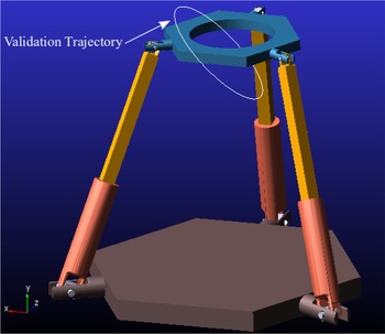
Inorder to validate the explicit dynamics given in Eq. (42), CAD model of the 3-UPU TPM is imported into MSC-ADAMS® software. Then, the output force of the actuators resulted from applying the desired trajectory,
 $\boldsymbol{{x}} = \boldsymbol{{x}}_d$
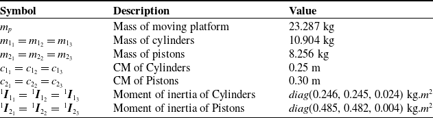
, to both the MSC-ADAMS and the robot’s explicit dynamic model is logged. By comparing these two results, the accuracy of the dynamic model is determined. A view of the 3-UPU TPM model in MSC-ADAMS may be seen in Fig. 4. Besides, the parameters of the considered 3-UPU TPM model have also been reported in Table I.
3-UPU TPM model in MSC-ADAMS®.

Parameters of the considered 3-UPU TPM

To verify the dynamics model of the 3-UPU manipulator, validation trajectory is considered as
 $\boldsymbol{{x}} =a \left[sin(2 \pi t), sin(2 \pi t), cos(2 \pi t) \right]^T+\boldsymbol{{x}}_0$
, where a and
 $\boldsymbol{{x}}_0$
is defined as
 $a = 0.2\;(m)$
and
 $\boldsymbol{{x}}_0=[0;1.1;0]^T\;(m)$
, respectively. Moreover, the external disturbance
 $\boldsymbol{{f}}_d$
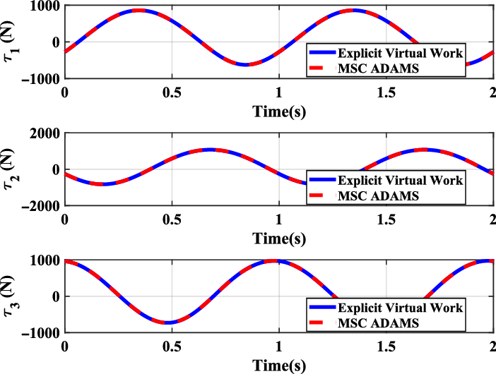
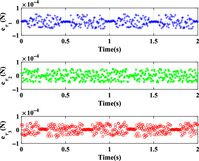
is considered zero. Therefore, by giving these trajectories to the explicit dynamics model and the MSC-ADAMS® model, the results of the explicit dynamic verification and its error are reported in Figs. 5 and 6, respectively.
Explicit dynamics verification of 3-UPU TPM with MSC-ADAMS®.

Error of explicit dynamics verification with MSC-ADAMS®.

As shown in Figs. 5 and 6, respectively, the explicit dynamic formulation of the 3-UPU TPM is verified with the accuracy of
 $10^{-4}$
, and applying other trajectories such as the third-order polynomial and multi-sine trajectories will not affect the result, and the verification error will always remain in the
 $10^{-4}$
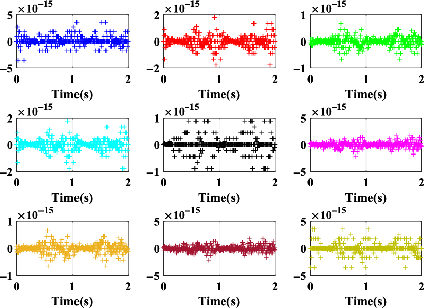
bound. In addition, to ensure the validity of Eq. (47), which is an important feature in the design of model-base controllers, its value is reported in Fig. 7. As it can be seen in Fig. 7, the Eq. (47) is always valid because the difference between the two sides of the equation is equal to the machine precision in numerical calculations.
Error of verification for
 $\dot{\boldsymbol{{M}}}-2\boldsymbol{{C}}$
.

6.2 Comparison of simple and complete dynamic model
Inthis section, by comparing the accuracy of the simple and the achieved complete dynamic mode, the effect of considering the simple model of universal joints on the dynamic model is examined. For this purpose, it is necessary to consider
 $ \boldsymbol{\omega}_{i}=\boldsymbol{\omega}_{\bot_i} $
and
 $ \dot{\boldsymbol{\omega}}_{i}=\dot{\boldsymbol{\omega}}_{\bot_i} $
to create a simplified model of the robot [Reference Hraiech, Chebbi, Affi and Romdhane18, Reference Xiangzhou, Yougao and Hongzan20]. Hence, it suffices to set
 $\boldsymbol{\mathcal{J}}_{\omega_{s_i}}=0$
and
 $\dot{\boldsymbol{\mathcal{J}}}_{\omega_{s_i}}=0$
in equations (13) and (30), respectively. In addition, assuming no disturbance force is applied to the moving platform, forces of the actuators can be classified into the following parts:
 \begin{equation}\tau =\boldsymbol{\tau}_M+ \boldsymbol{\tau}_C+ \boldsymbol{\tau}_g,\end{equation}
in which
 $\boldsymbol{\tau}_M$
denotes actuator forces generated from mass matrix terms,
 $\boldsymbol{\tau}_C$
is actuator forces generated from Centrifugal and Coriolis terms, and
 $\boldsymbol{\tau}_g$
shows actuator forces generated from the gravitational terms. It should be noted that angular velocity and acceleration terms of limbs have no effect on
 $\boldsymbol{\tau}_g$
, and therefore,
 $\boldsymbol{\tau}_g$
is not considered in the later comparison. In addition, kinetic energy
 $K=\frac{1}{2} \; \dot{\boldsymbol{{x}}} ^T \boldsymbol{{M}}(\boldsymbol{{x}}) \dot{\boldsymbol{{x}}}$
is used as another measurement of the robot mass matrix values.
Therefore, using the following normalized root mean square error (NRMSE) [Reference Ljung and Singh35], the comparison will be drawn:
 \begin{equation}NRMSE= 100 \left( 1- \frac{|| \boldsymbol{\tau}_F- \boldsymbol{\tau}_S ||}{||\boldsymbol{\tau}_F- mean\left(\boldsymbol{\tau}_F \right)||} \right)\end{equation}
in which
 $\boldsymbol{\tau}_F$
and
 $\boldsymbol{\tau}_S$
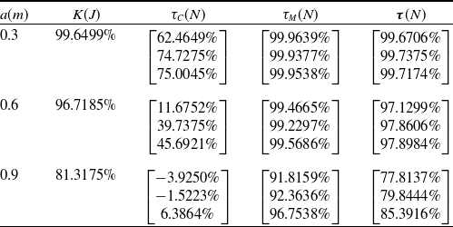
denote actuator forces generated from the full and the simple dynamic model, respectively. Accordingly, by taking the parameters reported in Table I and the validation trajectory ofSection 6.1 into account, the results of comparing the kinematic and dynamic sections are reported in Tables II and III, respectively.
NRMSE of angular velocity and acceleration of 3-UPU TPM limbs

NRMSE of different parts of actuator forces

As canbe seen from Table II, the greatest loss of accuracy occurs in the y component of the angular velocity and acceleration of the limbs. Moreover, by examining Table III, it can be deduced that for the values assumed for the robot and trajectory parameters, the simple and complete models are almost the same, and uncertainty only exists in
 $\boldsymbol{\tau}_C$
. However, since
 $\boldsymbol{\tau}_c$
is relatively smaller than
 $\boldsymbol{\tau}_M$
, uncertainty in
 $\boldsymbol{\tau}$
would be insignificant.
On the other hand, in cases where the amount of
 $\boldsymbol{\tau}_c$
is high, it can be expected that the values of uncertainties in
 $\boldsymbol{\tau}$
will increase. Therefore, a trajectory similar to Section 6.1 but with a variable amplitude is considered to investigate the effect of accelerating the trajectoryFootnote 2 on the uncertainties of
 $\boldsymbol{\tau}$
. Thus, the results of only the robot dynamics are examined and reported in Table IV.
Effect of faster trajectory on the NRMSE of different parts of actuator forces

As can be seen from Table IV, by accelerating the trajectory, the accuracy of the model decreases, and this is more evident in centrifugal and Coriolis terms, as expected. In this case, there is significant structural uncertainty in the dynamic model, which can reduce the accuracy of the model-based controllers to control the robot in fast trajectories. Consequently, using the complete dynamic model of 3-UPU TPM in fast trajectories is strongly recommended.
7. Conclusion
Inthis paper, the explicit dynamic formulation of a general 3-UPU translational parallel manipulator is addressed. First, all the kinematic models of the robot are carefully examined, and all effective terms are modeled. Then, the complete implicit dynamic of the robot is derived, using the principle of virtual work. The explicit dynamic formulation is derived then, by using a modification, and its properties are proven. To validate the proposed formulation, a prototype of the 3-UPU TPM is modeled in MSC-ADAMS® software, and the results of the explicit dynamic formulation are validated via this model. The validation error accuracy in the order of
 $10^{-4}$
verifies the correctness of the presented formulation in this paper. The obtained explicit dynamics model can be used to implement a wide range of model-based controllers on 3-UPU TPM.
Author Contributions
A. Hassani developed the theoretical formulations, performed the analytic calculations, and performed the numerical simulations. Both S. A. Khalilpour and A. Bataleblu authors helped perform the analysis with constructive discussions. H D. Taghirad conceived the original idea and supervised the project.
Financial Support
The authors appreciate the support from Iranian National Science Foundation (INSF) under grant number 99028112.
Conflicts of Interests
The authors do not have any conflicts of interest.
Ethical Considerations
The authors declare none.