


I. INTRODUCTION
At present, the possibility of carbon nanotube's (CNT) application as centimeter and millimeter wavelength range antennas is under investigation because of the possibility of mass production of centimeter-long CNTs. The area of application of such antennas is their use for interconnection between nanoelectronic circuits and macroscopic devices.
The electric length of nanotube, which is larger than electric length of metallic vibrators, is mentioned in [Reference Yin and Baoqing1–Reference Hanson5]. Because of that, the resonances of input impedance are observed in the millimeter wavelength range for 20–50 µm length nanotubes.
The problems, which have to be solved for effective application of CNTs as nanoantennas are high resistance per unit length and relatively low efficiency. These factors significantly influence the impossibility of CNT antenna's usage for large distances. The researches of ways to increase the nanoantennas' efficiency are being performed, and the first results show that efficiency of radiation could be improved by the use of several (up to few hundred) nanotubes distant from each other on a length of the order of CNT's radius.
The main objective of this work is to determine the circumstances to lower working frequency of CNT vibrator – by means of increase of its length and by their placing in dielectric.
II. THEORY
To calculate properties of CNT antennas, we applied the modified collocation method, presented in [Reference Lerer, Kleschenkov, Lerer and Labunko6]. Let us consider that the surface current j(z′) on a nanotube, which has only longitudinal component and does not depend on the azimuth φ. Besides, we shall ignore the current at the edges. In this case, we obtain

where E e(z) is the external field, A the vectorial potential, which could be expressed in the following form according to simplifications, indicated above:

where 2l is the vibrator's length, and a is its radius,

K(P) is the complete elliptic integral of the first kind,  .
Let us write down boundary conditions at the vibrator's surface:

ρn is the surface resistance, which for CNT can be expressed in the following form [Reference Hanson5]:

where νF is the Fermi speed (for CNT νF = 9.71 × 10⁵ m/s), ν the relaxation frequency (for CNT ν = 3.33 × 10¹¹ Hz), e the electron charge, and  the Planck's constant (Fig. 1).
The model of the CNT.

Substituting (1) into (2) we obtain

Let us make some transformations:  , where k, Z c is the wave number and wave impedance in a dielectric with permittivity and permeability equal to ɛ and μ, correspondingly. Then the above equation could be expressed in the following form:

where  , and
 .
Differential equation (3) has the following solution:

where C, D are unknown constants, A 1 is the particular solution of the following differential equation:

A 2 the particular solution of the following differential equation:

Green function for differential equations (5, 6) is

therefore,


Substituting (7) and (8) into (4) we obtain integral equation (IE) in unknown j(z)′:

The above calculations could be easily generalized for the system of N parallel vibrators (Fig. 2):

where j ν is the current density on νth vibrator, ν, μ the vibrators' indices, related to point of origin z′ and observation point z, correspondingly; a ν, L ν the radius and generatrix of vibrator,  the kernel of IE:


The system of parallel CNTs.

If points z and z′ do not belong to the same vibrator, i.e. ν ≠ μ, the distance between vibrators is much larger than a ν, so the kernel of IE becomes

Here R is the distance between point, lying at the vibrators' axes.
If points z and z′ belong to the same vibrator, i.e. ν = μ, then the function g νμ(z,z′) contain singular part  , which can be expressed in terms of complete elliptic integral of the first kind K(P ν):

As the direct application of the collocation method is impossible to solve the IE with singular kernel, the source equations were transformed first. The static singular part of the kernel was analytically isolated. Transformed IE was solved by means of the collocation method [Reference Lerer, Kleschenkov, Lerer and Labunko6]. On solving, the quadrature considering the edge condition was used:
To solve IE by means of modified collocation method let us consider the solution of IE (9) with the kernel (10). To analytically isolate the singularity in current behavior at the vibrators' edges we shall search the solution in the following form:

where  , and
 is the unknown function.
The kernel of IE (9) at ν = μ and  have logarithmic singularity:

Let us perform the regularization of the IE by isolating this singularity in explicit form. To do that let us transform the μth term of the sum in (9):


In expressions (13) and (14) we can set  , i.e. isolate the logarithmic part, or we can isolate the whole static part by setting
 .
If we set  , then integral (14) is calculated in analytical form:

In IE (9) let us substitute the variables  , then

where  .
To calculate the integral I 0,μ(z) we shall use the following expression:


which can be easily obtained using the integral's value:

where T n(x) is the Chebyshev's polynomials of the first kind.
In the second case, we have to make some additional transformations while calculating the integral (14):

Integral in (14a) does not contain any singularities and is calculated numerically.
The first integral in (13) does not have a singularity at  , and so IE (9) after transformation could be solved by means of the collocation method.
Let us substitute the integrals with the rectangle quadrature with the number of nodes M and require the satisfaction of transformed IE in nodes  and at the vibrator's edges
 . Thus, the solution of IE (9) is reduced to solving of the system of linear algebraic equations, which contains
 equations and
 unknowns:
 :
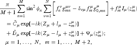
where  , δνμ is the Kronecker symbol.
As was mentioned above, the use of expression (11) as  is in preference, because logarithmic singularity poorly describes the IE's kernel for thin vibrators. The number of quadrature nodes at calculating the integral (13) in this case weakly depends on the ratio a/l, and is less than at use of expression (12), i.e. the order of the system will be smaller, and so the calculation time will be significantly reduced. On calculating (14a), we can use the higher order of quadrature, than on calculating (13). Because the integral (14a) does not depend on the frequency, it is calculated only once, and the time of its calculation weakly affects the overall calculation time.
III. RESULTS OF NUMERICAL CALCULATION
Input impedance of only single-walled CNTs of different lengths was investigated (Fig. 3). Here and further we use normalized R 0 = h/(2e 2) ≈ 12.9 kΩ resistance. Solid lines – real part of Z in, dashed lines – imaginary part.
The dependence of input impedance on frequency for nanotubes of radius a = 2.712 nm. Curves 1 – l = 10 µm; 2 – l = 50 µm; and 3 – l = 100 µm.

In this frequency range, the CNT with half-length l = 10 µm has three pronounced resonances. In case of CNT with l = 50 µm the number of resonances is much greater, and their amplitude is less than in case of l = 10 µm. It is necessary to point out that for the imaginary part of l = 50 µm CNT's input impedance is negative up to 300 GHz. Thus, there are no radiation resonances for nanotube antenna of 50 µm length in frequency range up to 300 GHz. Mean value of real and imaginary parts of input impedance of l = 100 µm CNT is of the same order, that in case of l = 50 µm, but there are no resonances at frequency range under investigation. The character of curves of input impedance of l = 100 µm CNT is analogous to the curve of traditional dipole antenna of classic metals. Thus, the increase of the nanotube's length does not lead to the appearance of resonances in the centimeter wavelength range.
In Fig. 4, the results of calculation of CNT antenna, placed in dielectric, are presented. An increase of dielectric permittivity leads to the increase in the number of resonances in the frequency range under investigation, and to the decrease in resonant frequencies values. The value of input impedance also decreases.
The dependence of input impedance on frequency for a single nanotube of radius a = 2.712 nm and l = 10 µm. Curves 1 – ɛ = 1; 2 – ɛ = 3; and 3 – ɛ = 10.

As mentioned above, the electric length of a nanotube vibrator is much greater than that of a metal vibrator. Therefore, the current distribution on a CNT vibrator is much more complicated and has some extremums (Fig. 5).
The current distribution on a nanotube with l = 10 µm, a = 2.712 nm. Solid curves – ɛ = 1, dashed curves –ɛ = 10. Curves 1 – f = 100 GHz; 2 – f = 1000 GHz; and 3 – f = 1000 GHz, perfect metal.

In Fig. 6, the results of calculation of the system of two parallel nanotubes with l = 10 µm, distant from each other on d = 1 µm, at different values of the CNT's radius a are presented. The increase in the radius leads to a decrease in the number of resonant frequencies. Subsidiary maximums on frequency dependency appear because of interaction between nanotubes'.
The dependence of input impedance on frequency for two parallel nanotubes, half-length l = 10 µm, distance between nanotubes d = 1 µm, curves 1 – a = 2.712 nm; 2 – a = 0.678 nm; and 3 – a = 0.339 nm.

Also the frequency dependencies of far field for the systems, containing several nanotubes disposed in line, are presented. The increase in the number of nanotubes leads to significant increase in the far field.
Also the CNT's radiation patterns were calculated (Figs 7 and 8). In this case, the nanotubes of l = 10 µm and radius a = 2.712 nm were considered. The radiation pattern for the systems, which contain of one, three, and five nanotubes, disposed parallel in line, are presented. The radiating nanotube in case of three and five antenna systems was the one at the end, others being situated in line along the azimuth φ = 0. The plane, perpendicular to the vibrators, was selected, and the calculation was performed under such frequencies, where the far field reaches its maximum for every investigated system.
Radiation pattern of the systems, consisting of parallel nanotubes, distant on 10 nm from each other. Curves: 1 – single nanotube (frequency f = 160 GHz); 2 – three nanotubes (frequency f = 180 GHz); and 3 – five nanotubes (frequency f = 220 GHz).

Radiation pattern for the systems, consisting of parallel nanotubes, distant from each other on 100 nm. Curves: 1 – single nanotube (frequency f = 160 GHz); 2 – three nanotubes (frequency f = 140 GHz); and 3 – five nanotubes (frequency f = 180 GHz).

The radiation pattern of a single nanotube has an expected shape and coincides with the radiation pattern of a classic vibrator. In case of three and five nanotubes systems, the radiation pattern has a clearly defined maximum. It is necessary to say that maximums on radiation patterns correspond to opposite direction of the arrangement of antennas. In case of systems, where the distance between nanotubes is equal to 100 nm, the directivity is more clearly defined than for systems with d = 10 nm.
IV. CONCLUSION
The effective method of CNT antennas' parameters calculation was developed. The investigation of input impedance for the systems of parallel radiating nanotubes has shown that an increase of antennas' length leads to an increase in the number of resonances in the frequency range under investigation and simultaneously leads to efficiency drop. Thus, consequently, it is not possible to reach efficient radiation at the centimeter frequency range by simply increasing the antennas' dimensions. But placing of CNT in dielectric it is possible to decrease the resonance frequency at the same physical dimensions of antenna. The use of the system of parallel nanotubes leads to the appearance of intermediate extremums, which become less expressed if the distance between nanotubes is increased. To increase the radiation efficiency of nanotubes, it seems reasonable to use several nanotubes, distant one from another on the distance of CNTs' radius' order. The use of the systems of parallel nanotubes makes possible the creation of directional antennas.
ACKNOWLEDGEMENT
The work was supported by RFBR (project RFBR№ 09-02-13530 ofi_c).
 Alexander M. Lerer was born in 1946, Ph.D, professor of department of applied electrodynamics and computer modeling, Physics faculty, Southern federal university. The area of scientific interests – high-frequency elcectrodynamics, mathematical theories of diffraction of electromagnetic waves, mathematical modeling of microwave optical and X-ray frequency range devices.
 Victoria V. Makhno was born in 1980, Ph.D, docent of department of informatics and numerical experiment of Southern federal university. The area of scientific interests – high-frequency elcectrodynamics, mathematical theories of diffraction of electromagnetic waves, mathematical modeling of microwave optical and X-ray frequency range devices.
 Pavel V. Makhno was born in 1984, Ph.D, assistant of department of applied electrodynamics and computer modeling, Physics faculty, Southern federal university. The area of scientific interests – high-frequency elcectrodynamics, mathematical theories of diffraction of electromagnetic waves, mathematical modeling of microwave optical and X-ray frequency range devices.



