1. Introduction
Robot’s navigation in a dynamic environment with an optimal path is challenging. The uncertainty caused by the movable obstacle and the limited calculational resource of the onboard processor make it difficult to avoid collision and optimize the path in real time. The dynamicity and uncertainty also exist in the multi-robot navigation process in complex and constrained environments [Reference Zhang, Li and Zhou1]. In the long-term state, tasks (exogenous events) can be assigned to the system at any time, such as when modular robots continuously switch configurations within the configuration sequence [Reference Zhang, Zhou and Li2]. It is challenging for the robot to keep a stable planning efficiency and robust optimization capability.
Various frameworks of path planning in the dynamic time-varying configuration space have been proposed by researchers. The lifelong planning A* (LPA*) and shape-aware lifelong planning A* (SLPA*) [Reference Yoon and Shim3] can adapt to changes on the map without searching the whole map again. The increase in the resolution of the grid map reduces planning efficiency. The cost of the grid is centered around the robot’s position, which must be recalculated whenever the robot moves. The optimization-based methods, such as evolutionary algorithm (EA) [Reference Mishra, An, Sidoti, Han, Ayala, Hansen, Pattipati and Kleinman4], genetic algorithm (GA) [Reference Yang, Liu and Li5], and particle swarm optimization (PSO) [Reference Roberge, Tarbouchi and Labonte6], model the navigation as an optimization problem under complex dynamic constraints. The time consumption of solving the optimization problem is substantial, making it challenging to meet the real-time replanning frequency. The fine dynamic window (FDW) [Reference Wang and Xu7] adjusts the global path when obstacles disturb the motion of the robot. Model predictive control (MPC) [Reference Hu, Zhao and Qu8] is also utilized in generating trajectory in control space. The methods achieve good conflict avoidance, but they cannot switch the path in a large range when the global path is completely blocked.
The Rapidly-exploring Random Tree (RRT)-based methods can deal with time-varying configuration space for low computational cost and completeness. Branch pruning and reuse are the most common methods to reduce computational cost and improve real-time performance. The execution extended RRT (ERRT) method [Reference James Bruce9] generates a new tree with waypoints in the tree growth in previous planning. The efficient bias-goal factor RRT (EBG-RRT) method [Reference Yuan, Liu, Zhang and Pan11] makes use of potential cache information and finds an optimal path to repair the RRT tree. The elastic band-based rapidly exploring random tree (EB-RRT) [Reference Wang, Meng and Khatib19] utilizes the elastic band method in the dynamic planner to optimize trajectories from the global planner. RRT-based method is also utilized in
 $s-t$
space to solve the speed profile optimization problem of obstacle avoidance in dynamic environment [Reference Du, Li, Zheng and Liu20]. Searching for the optimal path using an RRT-based method presents challenges due to its inherent randomness. It is difficult for the RRT-based method to identify improved path clusters after the initial path has been generated.
Some RRT*-based methods in the dynamic environment are proposed, which combine the asymptotic optimality of RRT* and real-time planning. RRTX [Reference Otte and Frazzoli10] repairs a search graph over the whole navigation, which realizes a fast response to the change in environment. RT-RRT* [Reference Naderi, Rajamäki and Hämäläinen12] is improved from RRT*. The root node of the RRT* tree transforms along with the robot, and the whole tree is reconnected according to the cost by the rewiring calculation. An extended version of the RRT* [Reference Pfotzer, Klemm, Roennau, Zöllner and Dillmann13] is proposed for reconfigurable robots to overcome previously unknown obstacles. The multiobjective RRT* (MOD-RRT*) [Reference Qi, Yang and Sun14] generates the initial path by RRT* and replans a new path to avoid obstacles by selecting an alternative node with the Pareto theory. Dealing with mobile obstacles, Risk-RRT* [Reference Chi and Meng15] models the typical motion patterns of obstacles with Gaussian Processes and calculates the risk of collision to guide the node generation. A dynamic path planning method utilizing RRT* rewiring handles the randomly moving obstacles and target in real time [Reference Katiyar and Dutta16]. The mechanism established in the configuration space by the RRT*-based method is centralized. The cost of each tree node is dependent on the root node, that is, the robot’s location during planning. When the center changes, the existing tree cannot be directly reused, negatively affecting real-time performance.
The existing path planning methods often construct a mechanism centered around the current position of the robot and terminate the construction once the mechanism reaches the target position. The cost of nodes and the connection relationships between parent and child nodes are based on the center, that is, the mechanism is optimized for the current center. As the robot navigates in a dynamic environment, the path must be adjusted in real time. The changing map and the mobile center that move with the robot make the mechanism built in the previous planning infeasible or not optimized. The mechanism needs to be recalculated or rewired, which reduces the algorithm performance in dynamic planning.
The decentralized mechanism does not rely on the center and can be adjusted at a small cost when the environment changes, achieving large-scale reuse. The typical decentralization method is the Probabilistic Roadmap (PRM) method [Reference Jaillet and Simeon17, Reference Belghith, Kabanza and Hartman18], which involves a non-centered roadmap within the map. This method searches for the nodes in the roadmap that are closest to the starting and ending points of the robot as entrances and exits and establishes the optimal path through heuristic search within the roadmap. The pairwise connection pattern of PRM significantly increases the scale of connections as the number of nodes grows. The computational burden of optimizing search is heavy.
In this work, we aim at solving the real-time optimal path planning problem in a dynamic environment and propose the Cyclic Networking Rapidly Exploring Random Tree (CNRRT) method. The CNRRT generates a decentralized mechanism, including the map-covered tree and the cyclic branch, to construct a decentralized path network. The greedy-based iterative search finds the real-time near-optimal path in the path network. The branch prune, the reconnection, and the regrowth process are built to respond to the dynamic change of the configuration space. The CNRRT can obtain the near-optimal path in real time, which keeps a good balance between real-time performance and optimization capability. The decentralized tree structure allows CNRRT to cope with long-term running. The CNRRT can avoid collision locally and can switch paths in a wide range when the local path is completely congested. The contributions are summarized as follows:
-
(1) The CNRRT method creatively introduces cyclic connection into the acyclic RRT tree to construct a decentralized, omnidirectional, and consistent graph in the map. The cyclic connection increases the richness of RRT paths, which improves the coverage of different path clusters.
-
(2) An efficient searching method is built to obtain the near-optimal path in the cyclic path network. The method avoids the complex search in the cyclic graph by building the cyclic connection as an independent graph and executing the search via a simple acyclic graph of the RRT tree.
-
(3) The branch pruning, reconnection, and regrowth of the tree are built to respond to the dynamic environment, which ensures stable real-time performance and optimization capabilities of CNRRT in dynamic environments and task sequence scenarios.
This article is organized as follows. Section 2 formulates the optimal path planning problem that is solved in this article. Section 3 describes the details of the CNRRT method. Section 4 displays and analyzes the results of simulation and physical experiments. The characteristics of the CNRRT method are discussed in section 5 according to the experimental results. Section 6 concludes this article.
2. Problem formulation
The optimal path planning problem in a dynamic environment can be formalized as follows. The
 $d$
-dimensional configuration space, which changes with time step
 $k$
, is
 $X=(0,1)^d$
with
 $d \in \mathbb {N}, d \ge 2$
. The region that is prohibited to enter is marked with
 $X_{obs}$
. The moving obstacles exist in the configuration space and are included in
 $X_{obs}$
. The moving obstacle is an important factor that leads to the workspace changing. The other region without obstacles is defined as
 $X_{free}$
with
 $X_{free}=X \backslash X_{obs}$
. The goal state
 $g \in X_{free}$
and the initial state
 $o \in X_{free}$
of the robot are set in the configuration space. The optimal path planning problem in the dynamic environment is defined to search for the optimal path
 $L^{(k)}$
for the
 $k$
th time step, which connects the current position of the robot
 $r$
and the destination
 $g$
. The path
 $L^{(k)}$
is the set of path waypoints and satisfies the following three properties:
-
(1) Effectiveness: the current position
 $r$
of the robot can be transferred to
$g$
along the path
$L^{(k)}$
.
-
(2) Collision-free: no collision exists between
$L^{(k)}$
and the obstacles, that is,
$L^{(k)} \cap X_{obs}=\emptyset$
. -
(3) Optimality: the path
$L^{(k)}$
is optimal on certain evaluation criteria. In this work, we evaluate the quality of path
$L^{(k)}$
through the length in the Euclidean sense.


3. The CNRRT algorithm
The CNRRT method contains the Pre-build process and the Real-time Running process. The framework of the CNRRT method is shown in Figure 1. The Pre-build process builds the map-covered tree and the cyclic connection, which is offline and runs one time in the life cycle of CNRRT. The Real-time Running process contains the dynamic changes response and the iterative optimization search, which runs continuously in cycles. In each cycle, the Real-time Running process adjusts the map, the map-covered tree, and the cyclic connection through the dynamic changes response method according to the environment changes. The iterative optimization search method generates the optimal global path based on the current map, tree, and the cyclic connection in the cycle. The path is executed by the robot, which adjusts the robot’s motion in every planning cycle.
3.1. Map-covered tree generation
Rebuilding the whole tree in real time is time-consuming. The CNRRT method pre-builds a map-covered tree before real-time path planning.
Definition 1. (Map-covered tree), Let
 $G_{mc}=(V_{mc},E_{mc})$
indicate an acyclic graph in a
 $2$
-dimensional configuration space.
 $V_{mc}$
is the vertex set generated by random sampling from the root node
 $v_o$
.
 $E_{mc}$
is the edge set containing the edges between the child nodes
 $v_c$
and the parent nodes
 $v_p$
. The map-covered tree
 $G_{mc}$
is located in the free area on the map and follows:
 \begin{align} \begin{cases} V_{mc} \sim U(X_{free}) \\ E_{mc} = \{(v_c,v_p)|v_c,v_p\in V_{mc}\}. \end{cases} \end{align}
In Eq. (1),
 $U(X_{free})$
is the
 $2$
-dimensional Uniform Distribution in
 $X_{free}$
, which indicates the uniformity and universality of
 $G_{mc}$
and is different from RRT tree. The root node
 $v_o \in X_{free}$
can be selected arbitrarily. Let
 $v_r$
be the random point.
 $v_p$
is the closest tree node to
 $v_r$
, as well as the parent node of
 $v_c$
.
 $\boldsymbol {v_c},\boldsymbol {v_p},\boldsymbol {v_r}$
are the coordinate vectors of nodes
 $v_c,v_p,v_r$
.
 $l$
is the length of growth. The CNRRT randomly samples the free space to generate tree nodes
 $v_c$
at location
 $(x_c, y_c)$
by the classical RRT growing method as follows:
 \begin{align} \boldsymbol {v_c} = \boldsymbol {v_p}+l\frac {\boldsymbol {v_r}}{|\boldsymbol {v_r}|}. \end{align}
When the node quantity reaches the threshold
 $\mu _{mc}$
,
 $G_{mc}$
finishes growing.
Through the map-covered tree, a feasible path can be quickly generated by backtracking. In this work,
 $L^{(\cdot )}_{(*)}$
is defined as the path from node
 $(*)$
to
 $(\cdot )$
. Let
 $L_{v_e}^{v_l}$
represent the path in
 $G_{mc}$
from
 $v_e$
to
 $v_l$
, where
 $v_e$
is the closest tree node to the robot position and
 $v_l$
to the destination. Paths
 $L_{v_e}^{v_o}$
and
 $L_{v_l}^{v_o}$
are built by iteratively visiting the parent nodes from
 $v_e$
and
 $v_l$
to the root node
 $v_o$
. All nodes that are visited during the iteration make up
 $L_{v_e}^{v_o}$
and
 $L_{v_l}^{v_o}$
.
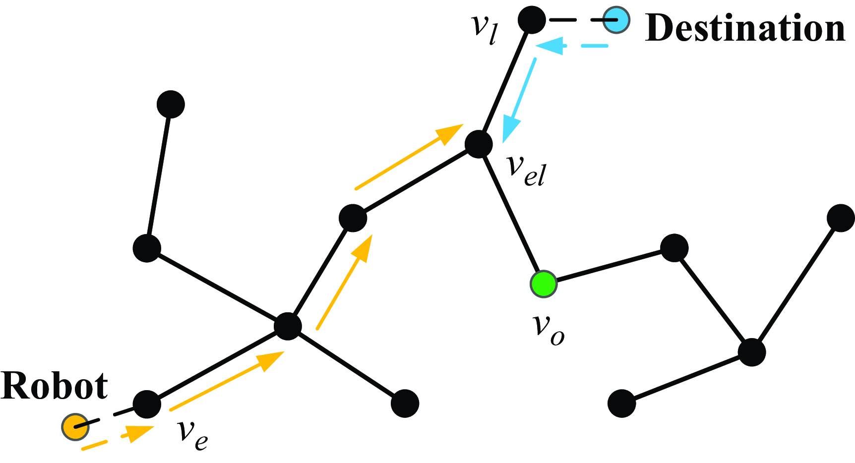
 $v_{el}$
is the first repeated tree node that appears in the backtracking from
 $v_e$
to
 $v_o$
and
 $v_l$
to
 $v_o$
, which is shown as Figure 2. The path
 $L_{v_e}^{v_l}$
is calculated as:
 \begin{align} L_{v_e}^{v_l}= L_{v_e}^{v_{el}} \cup L_{v_{el}}^{v_l}. \end{align}
The framework of the CNRRT method.

The path generation in
 $G_{mc}$
.

3.2. Cyclic branch connection
The path built from the map-covered tree is nonoptimal. For the acyclic graph, only one path is feasible in
 $G_{mc}$
and may not be located in the optimal path cluster. In the CNRRT, the cyclic branch is proposed and added to the map-covered tree to increase the diversity of the path on the map.
The typical situation of the acyclic map-covered tree and cyclic branch.

Definition 2. (Cyclic Branch), The cyclic branch is a graph
 $G_{cb}$
consisting of subgraphs
 $B_i$
as elements, that is,
 \begin{align} G_{cb} = \{B_i|B_i=(S_i,C_i),i \in \mathbb {N}\}, \end{align}
where
 $B_i$
represents the
 $i$
th cyclic connection consisting of the node set
 $S_i=\{v_{b,i},s_i,v_{t,i}\}$
and the edge set
 $C_i$
. The based node
 $v_{b,i} \in G_{mc}$
and the target node
 $v_{t,i} \in G_{mc}$
are connected by
 $s_i$
.
 $C_i$
follows:
 \begin{align} C_i = (v_{b,i}, s_i) \cup (s_i,v_{t,i}). \end{align}
With the cyclic branch, the map-covered tree turns into a circular connection graph. The cycle generated by the cyclic connection
 $B_i$
is denoted as
 $\Gamma _i$
. Let
 $L^{v_{b,i}}_{v_{t,i}}$
represent the path on
 $G_{mc}$
from the base node
 $v_{b,i}$
to the target node
 $v_{t,i}$
.
 $\Gamma _i$
satisfies
 \begin{align} \Gamma _i = L^{v_{b,i}}_{v_{t,i}} \cup C_i. \end{align}
Based on the map-covered tree, CNRRT continues sampling randomly on the map. The new branch
 $(v_{b,i}, s_i)$
from
 $v_{b,i}$
is generated toward the sampling point with nearest neighbours strategy and growth length
 $l$
. If the distance between the new node
 $s_i$
and the existing tree node
 $v_{t,i}$
is below the connecting threshold
 $\mu _c$
, the connection is built as follows:
 \begin{align} G_{cb} = G_{cb} \cup (S_i,C_i), \: \mbox {if } \|s_i - v_{t,i}\| \lt \mu _c. \end{align}
The connection is set to be virtual, that is,
 $s_i$
is not added to the map-covered tree, which maintains the simplicity of the map-covered tree and avoids the complicated searching cost of a cyclic graph. When the cyclic connection quantity reaches the threshold
 $\mu _{cb}$
,
 $G_{cb}$
finishes growing.
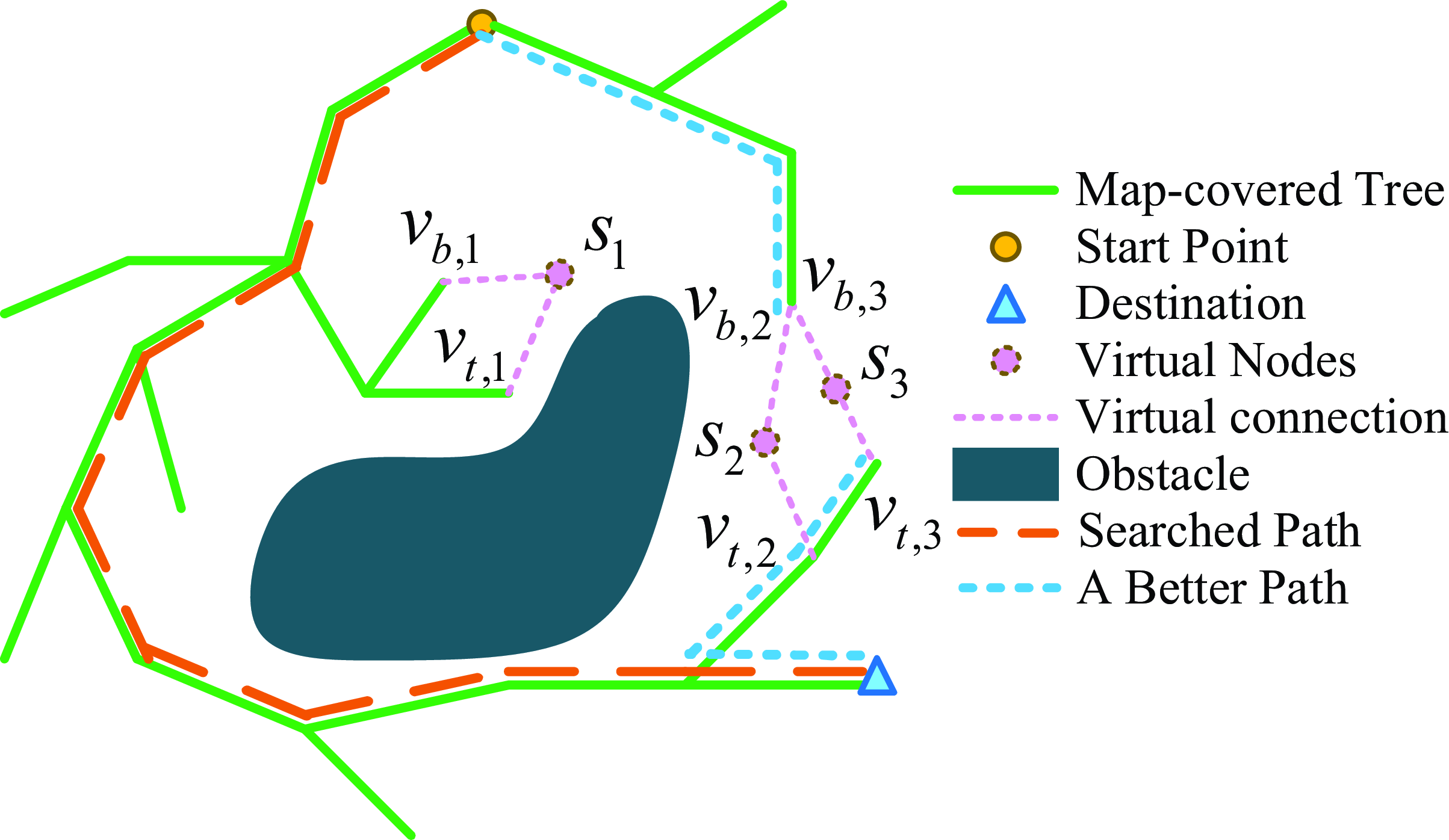
Some of the branches of cyclic connection are redundant or invalid, as shown in Figure 3. The two nodes connected by
 $s_1$
are close to each other. Considering the two paths from
 $v_{b,1}$
to
 $v_{t,1}$
, the one path via the map-covered tree is close in space to the other path via
 $s_1$
. The
 $s_1$
brings an insignificant diversity to the map-covered tree, which is invalid.
 $s_2$
and
 $s_3$
are redundant connections between the two branches because the paths via
 $s_2$
and
 $s_3$
are similar. We propose two screening criteria, named Significance and Proximity, to remove the invalid and redundant cyclic connection.
The Significance criteria is set to check for the node count in a cycle and filter the short loop. The Significance Threshold
 $\mu _s$
is used to judge whether the scale of a cycle can pass the inspection. For each cyclic connection node
 $s_i$
, the node count of path
 $L_{v_{b,i}}^{v_{t,i}}$
, that is,
 $card(L_{v_{b,i}}^{v_{t,i}})$
, is checked as follows:
 \begin{align} G_{cb} = G_{cb} \backslash (S_i,C_i), \: \mbox {if } card(L_{v_{b,i}}^{v_{t,i}}) \lt \mu _s. \end{align}
The Proximity criteria is introduced to remove the redundant connections. Two branches of the cyclic connection with a common endpoint are checked. The node counts in the two cycles are calculated. One of the connections is reserved if the difference in the node count between the two cycles is lower than the proximity threshold
 $\mu _p$
. In Figure 3, for example,
 $s_2$
and
 $s_3$
satisfy
 $v_{b,2} = v_{b,3}$
. The path
 $L_{v_{t,2}}^{v_{t,3}}$
is calculated as Eq. (3).
 $card(L_{v_{t,2}}^{v_{t,3}})$
is checked as follows:
 \begin{align} G_{cb} = G_{cb} \backslash (S_2,C_2), \: \mbox {if } card(L_{v_{t,2}}^{v_{t,3}}) \lt \mu _p. \end{align}
3.3. Response to dynamic changes
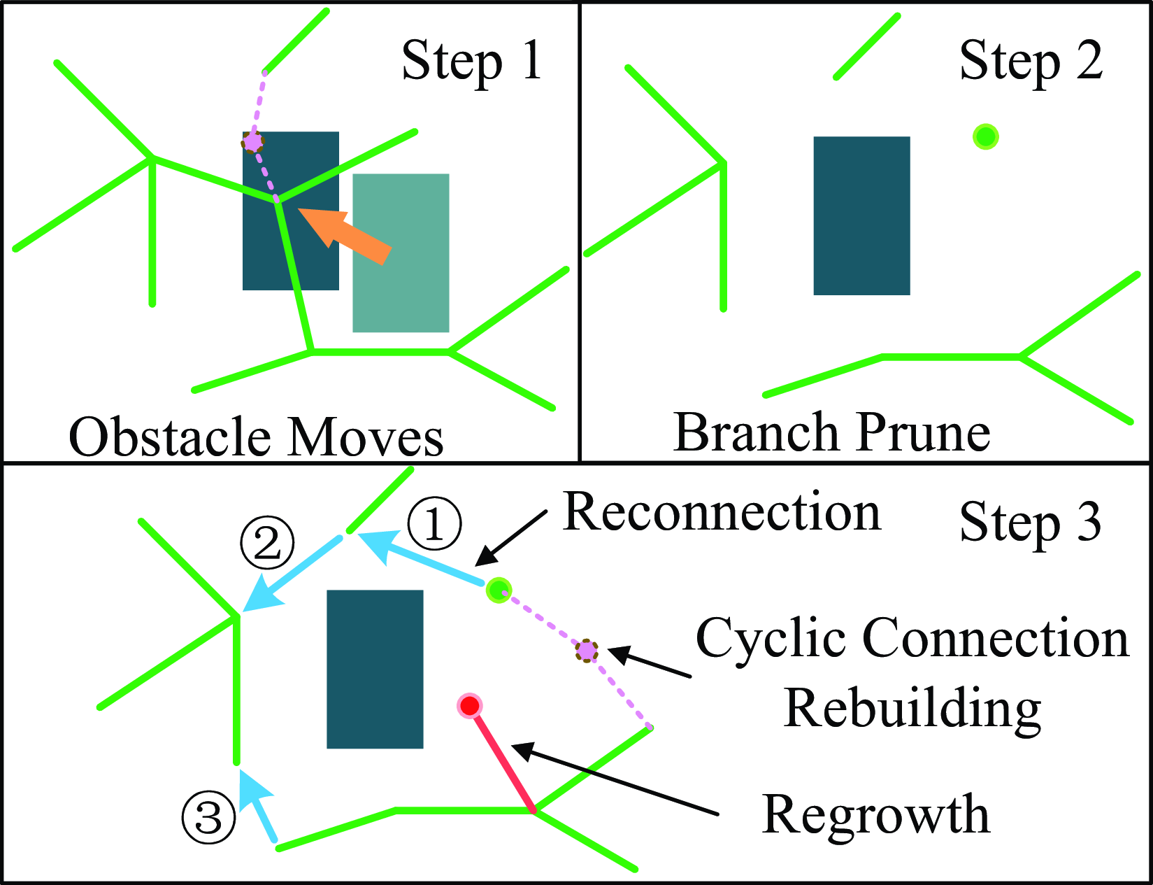
As the configuration space changes, the maintenance of the tree is proposed. Three critical components, such as branch prune, reconnection, and regrowth, are designed to maintain the effectiveness, connectivity, and uniformity of the map-covered tree and cyclic branch. The maintenance process is shown in Figure 4.
In every replanning process of CNRRT, the collision check for the tree
 $G_{mc}$
and the cyclic branch
 $G_{cb}$
is executed. The invalid nodes and broken edges are removed, which leads to multiple separate subtrees shown in the second step of Figure 4.
The subtrees from the branch prune process are needed to be reconnected. The classical growth method in RRT is utilized to connect the separate subtrees. The subtree with the least number of nodes is set to be the base subtree. Starting from the base subtree, a new branch is grown with Eq. (2) (shown as the blue line in the third step of Figure 4). From the subtree with the least node account, all the subtrees are merged until the whole map-covered tree recovers, shown in steps
 $\unicode{x2460}$
,
 $\unicode{x2461}$
, and
 $\unicode{x2462}$
in Figure 4. Choosing the subtree with the smallest scale as the base subtree increases the reconnection efficiency. The new branch, led by random sampling, is easier to grow in the area near the large subtree because it takes up more space to obtain a high probability of being sampled. Conversely, it may take many steps to grow the branches in the area near the small subtree, which increases the computational burden.
After the branch prune and reconnection processes, the total number of tree nodes and cyclic connection may be reduced below the threshold
 $\mu _{mc}$
and
 $\mu _{cb}$
. New tree nodes are added to the map by Eq. (2) (shown as the red nodes and red line in the third step of Figure 4). New branches of cyclic connection, which pass the Significance and Proximity check, are added to the map through Eq. (7) (shown as the dotted line in the third step of Figure 4). The uniformity of
 $G_{mc}$
and
 $G_{cb}$
is guaranteed by the regrowth process.
The maintenance of the map-covered tree and the cyclic branch when an obstacle moves in a time step.

3.4. Iterative optimization search
In every time step of replanning, the iterative optimization search process is executed to find the optimal path from the current location of the robot to the goal, which is utilized to update the currently executed path of the robot. The optimization problem can be described as searching for the shortest path in the path network.
Definition 3. (Optimization Problem), Let
 $\mathbb {L}$
denote the set of paths
 $L$
formed by the map-covered tree
 $G_{mc}$
and cyclic branch
 $G_{cb}$
. Let
 $\widetilde {L}$
denote the relaxed path of
 $L$
. The optimization problem is to search for the path
 $L_o \in \mathbb {L}$
which satisfies
 \begin{align} L_o=\mathop {\arg \min }_{\widetilde {L}}length(\widetilde {\mathbb {L}}). \end{align}
Path
 $L$
is composed of multiple straight lines with tortuous waypoints. A corrugated path with more nodes may be located in a shorter path cluster than a smooth path with fewer nodes. In CNRRT, the relaxation method is proposed to smooth the path, and the length of the smoothed path is utilized to describe the path quality. The basic relaxing calculation
 $R$
is defined as follows:
 \begin{align} R[L(v_j,\cdots, v_{j+m})]= \begin{cases} R[L(v_j,\cdots, v_{j+m/2})], & \mbox {if } (v_j,v_{j+m}) \cap X_{obs} \neq \emptyset \\ L(v_j,v_{j+m}), & \mbox {otherwise}. \end{cases} \end{align}
The output of the
 $R$
calculation is a line segment in the path. For a path with
 $M$
nodes
 $L(v_1,\cdots, v_M)$
, CNRRT checks whether the straight line between
 $v_j$
and
 $v_{j+m}$
passes through the obstacle area. If not, it replaces the original path segment with the connection
 $(v_j,v_{j+m})$
. Otherwise, it iteratively halves
 $m$
and checks the collision of
 $(v_j,v_{j+m/2})$
until finding a collision-free line
 $(v_j,v_{j+\widehat {m}}), \widehat {m} \le m$
. After the
 $R$
calculation, the path segment
 $L(v_j,\cdots, v_{j+m})$
is relaxed to
 $L(v_j,v_{j+\widehat {m}})$
. Then the
 $R$
calculation is re-executed with
 $j=\widehat {m}$
until
 $\widehat {m} = M$
, completing a round of relaxation. Repeating the relaxation round until no change of path occurs, the path relaxation finishes and outputs
 $\widetilde {L}$
. The relaxation method removes the redundant nodes to generate a shorter path. After extensive parameter debugging, we set
 $m$
to 5 and use the round-down function to calculate
 $m/2$
.
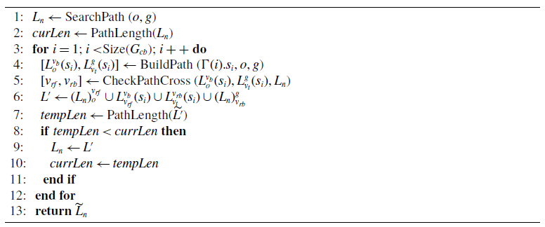
In the CNRRT, an iterative optimization method with the greedy strategy is proposed to search for the optimal path efficiently. The CNRRT traverses all of the cyclic connection in
 $G_{cb}$
to improve the initial path generated from the map-covered tree
 $G_{mc}$
. A map-covered tree with
 $N$
numbers of branches of cyclic connection is considered. The initial path
 $L_0$
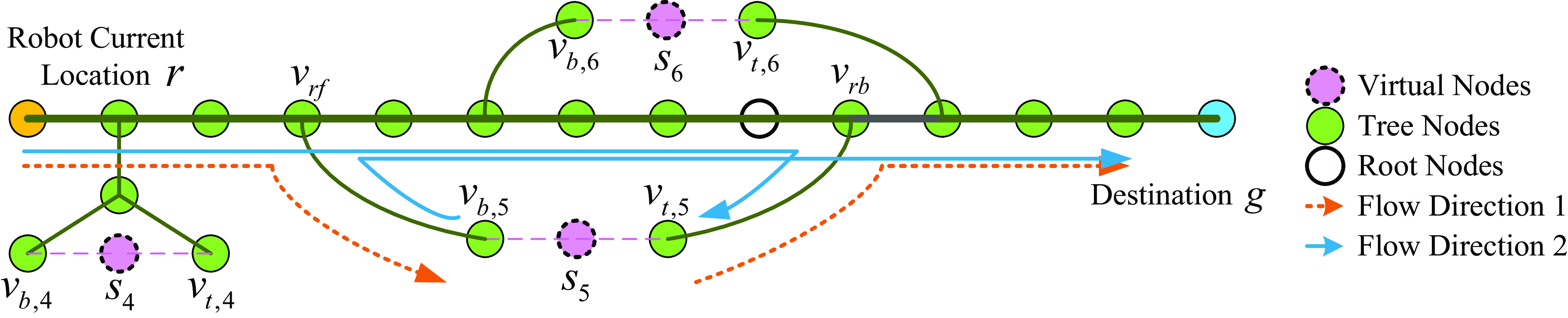
shown as the thick horizontal line in Figure 5 is firstly built from the map-covered tree. Let
 $L^{g}_{r}(s_i)$
denotes the path connecting the robot position
 $r$
and the destination
 $g$
via
 $s_i$
. The CNRRT traverses
 $L^{g}_{r}(s_i)$
forward and backward from
 $s_i$
until finding two nodes,
 $v_{rf}$
and
 $v_{rb}$
, repeating in the path
 $L_i$
of the
 $i$
th iteration. The candidate path
 $L'_{i+1}$
is built as follows:
 \begin{align} L'_{i+1}=(L_i)^{v_{rf}}_{r} \cup L^{v_{rb}}_{v_{rf}}(s_i) \cup (L_i)^{g}_{v_{rb}}, \end{align}
that is, the path segment
 $(L_i)^{v_{rb}}_{v_{rf}}$
between
 $v_{rf}$
and
 $v_{rb}$
is replaced by the cyclic connection path segment
 $L^{v_{rb}}_{v_{rf}}(s_i)$
where
 $L^{v_{rb}}_{v_{rf}}(s_i) \subseteq L^{g}_{r}(s_i)$
.
If
 $L'_{i+1}$
is shorter than
 $L_i$
after relaxation, the greedy strategy updates
 $L_i$
with
 $L'_{i+1}$
:
 \begin{align} L_{i+1}= \begin{cases} L_i, & \mbox {if } length(\widetilde {L}_i) \le length(\widetilde {L'}_{i+1}) \\ L'_{i+1}, & \mbox {otherwise}. \end{cases} \end{align}
For the cyclic connection
 $s_5$
, there are two paths with different flow directions which are shown as the blue line and orange dotted line in Figure 5. The repeating segment is utilized to distinguish the two different flow directions. The path without repeating nodes is selected to be the one arising from
 $s_5$
, as shown in Eq. (14):
 \begin{align} L^{g}_{r}(s_5)= \begin{cases} L^{v_{b,5}}_{r} \cup L^{g}_{v_{t,5}} \cup s_5, & \mbox {if } L^{v_{b,5}}_{r} \cap L^{g}_{v_{t,5}} = \emptyset \\ L^{v_{t,5}}_{r} \cup L^{g}_{v_{b,5}} \cup s_5, & \mbox {otherwise}. \end{cases} \end{align}
When the traversal of the cyclic connection list is complete, the path of the
 $N$
th iteration is the replanning result. The current path that the robot executes is updated with the replanning result when the current path is broken by the moving obstacle or the replanning result is shorter.
The topological graph of the path network. Three branches of the cyclic connection exist in the graph.

Iterative optimization search

3.5. Probabilistic completeness
As a method based on random sampling, the probabilistic completeness of our method needs to be analyzed. The probabilistic completeness means that if a path connecting
 $o$
and
 $g$
exists, the probability of finding this path tends to 1 with the node number in the tree tending to
 $\infty$
[Reference Karaman and Frazzoli22].
Theorem 3.1.
The CNRRT is probabilistic complete. Let
 $n$
and
 $h$
represent the node number in the tree
 $G_{mc}$
. There exist constants
 $a\gt 0$
and
 $n_0,h_0 \in \mathbb {N}$
such that
 \begin{align} P(\{\exists A_{CNRRT}\}) \gt 1-e^{-ah}-e^{-an}+e^{-a(h+n)}, \forall h\gt h_0,n\gt n_0. \end{align}
 $Proof.$
From Theorem 16 in reference [Reference Karaman and Frazzoli22], the classical RRT method is probabilistic completeness, such that
 \begin{align} P(\{\exists A_{RRT}\}) \gt 1-e^{-an}. \end{align}
On the map-covered tree of CNRRT, the path search process consists of two independent processes, one from
 $v_o$
to
 $o$
and the other from
 $v_o$
to
 $g$
. Each path search process is executed with the RRT method. Let event
 $A_o$
and
 $A_g$
denote those two processes that find the path successfully with the map-covered tree. They satisfy
 \begin{align} \begin{cases} P(\{\exists A_o\}) \gt 1- e^{-ah} \\ P(\{\exists A_g\}) \gt 1-e^{-an}. \end{cases} \end{align}
Thus,
 \begin{align} P(\{\{\exists A_o\} \cap \{\exists A_g\}\}) \gt 1-e^{-ah}-e^{-an}+e^{-a(h+n)}. \end{align}
The CNRRT method adds the cyclic connection to the map-covered tree. The cyclic connection generates additional paths to the original path generated by the map-covered tree, which increases the probability of CNRRT discovering the feasible path. The worst situation is that the cyclic connection cannot find any additional path, which makes the success probability equal to the map-covered tree. The event that the map-covered tree finds the feasible path is the sub-event of CNRRT finding the feasible path, that is,
 $\{\{\exists A_o\} \cap \{\exists A_g\}\} \subseteq \{\exists A_{CNRRT}\}$
.
Then we can get
 \begin{align} P(\{\exists A_{CNRRT}\}) \geq P(\{\{\exists A_o\} \cap \{\exists A_g\}\})\gt 1-e^{-ah}-e^{-an}+e^{-a(h+n)} \end{align}
and satisfies
 \begin{align} \lim _{\substack {h \rightarrow \infty \\ n \rightarrow \infty }}P(\{\exists A_{CNRRT}\})\gt \lim _{\substack {h \rightarrow \infty \\ n \rightarrow \infty }}1-e^{-ah}-e^{-an}+e^{-a(h+n)} = 1. \end{align}
Thus, the probability of finding the path tends to 1 with the node number of CNRRT tending to
 $\infty$
. The CNRRT is probabilistic complete.
4. Simulations and experiments
4.1. Simulation configuration
In this section, series simulations, including the key parameter test of CNRRT, the comparative simulation, the long-term running test of CNRRT, and the real-world experiment, are executed to prove the effectiveness of the CNRRT method. All of the simulations are executed in MATLAB R2017b on Dell Inspiron 7590 with Intel i7 CPU at 2.60 GHz. The robot operating system (ROS) Melodic on Ubuntu 18.04 is utilized in the real-world implementation. The Theta* method finds paths that are almost as short as true shortest paths on grids [Reference Daniel, Nash and Koenig21], which is involved as the shortest path generator to strictly evaluate solution quality.
4.2. Simulation of the key parameters in static environment
The key parameters in CNRRT, such as the node quantity threshold
 $\mu _{mc}$
, the significance criteria
 $\mu _s$
, and the proximity criteria
 $\mu _p$
, are simulated to test the influence on the performance of CNRRT.
The count number of map-covered tree and time cost under different
 $\mu _{mc}$
.

A
 $640 \times 480$
(pixel) sized map with five regular obstacles is built.
 $10 \times 10$
grids are divided to calculate the node distribution. In the simulation about the node quantity threshold
 $\mu _{mc}$
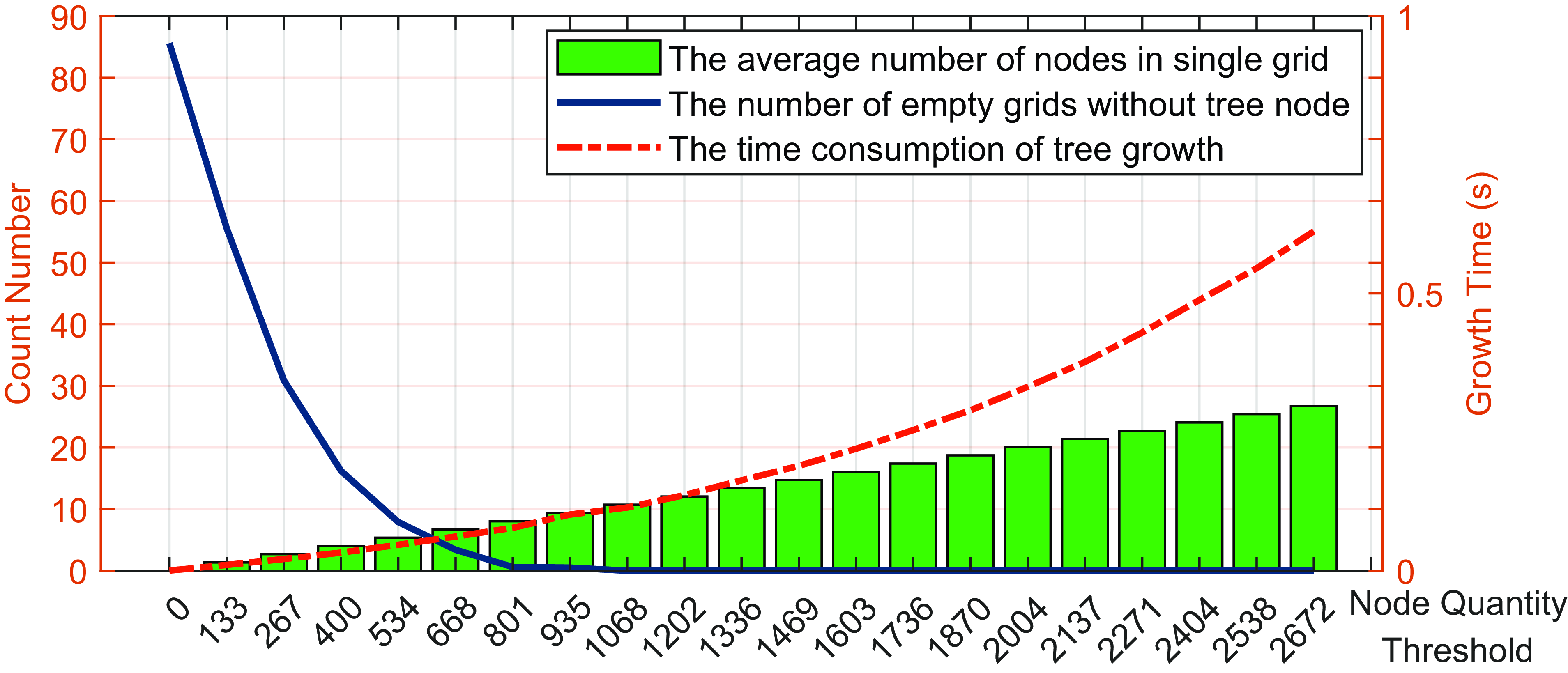
, the growth process of the map-covered tree is recorded as tree nodes increase. The number of tree nodes in a single grid, the number of empty grids, and the growth time are shown in Figure 6. With the increase of
 $\mu _{mc}$
, the mean count of nodes in a single grid linearly increases, which means that the growth of
 $G_{mc}$
is uniform in free space
 $X_{free}$
. The empty grids disappear when
 $\mu _{mc}$
equals 801 (about 0.3% of the area of
 $X_{free}$
).
 $\mu _{mc}$
should not be chosen too small to prevent unexplored areas on the map. The time consumption increases accelerated with a large value of
 $\mu _{mc}$
, which means that the speed of growing the new branch slows down with the increase of tree nodes. The deceleration of growing speed is caused by the duplicate node detection of CNRRT. If the newly generated node is close to one of the existing tree nodes, the new node is removed. In the latter of growth, it has a higher possibility that a new node duplicates the existing tree nodes, which increases the time cost to add a new node to
 $G_{mc}$
. Thus, an appropriate
 $\mu _{mc}$
is suggested to be set in
 $[0.3\%,0.8\%]$
of the area of
 $X_{free}$
.
The influence on optimal path solving from various Significance Threshold
 $\mu _s$
and Proximity Criteria
 $\mu _p$
are tested.
 $\mu _s$
and
 $\mu _p$
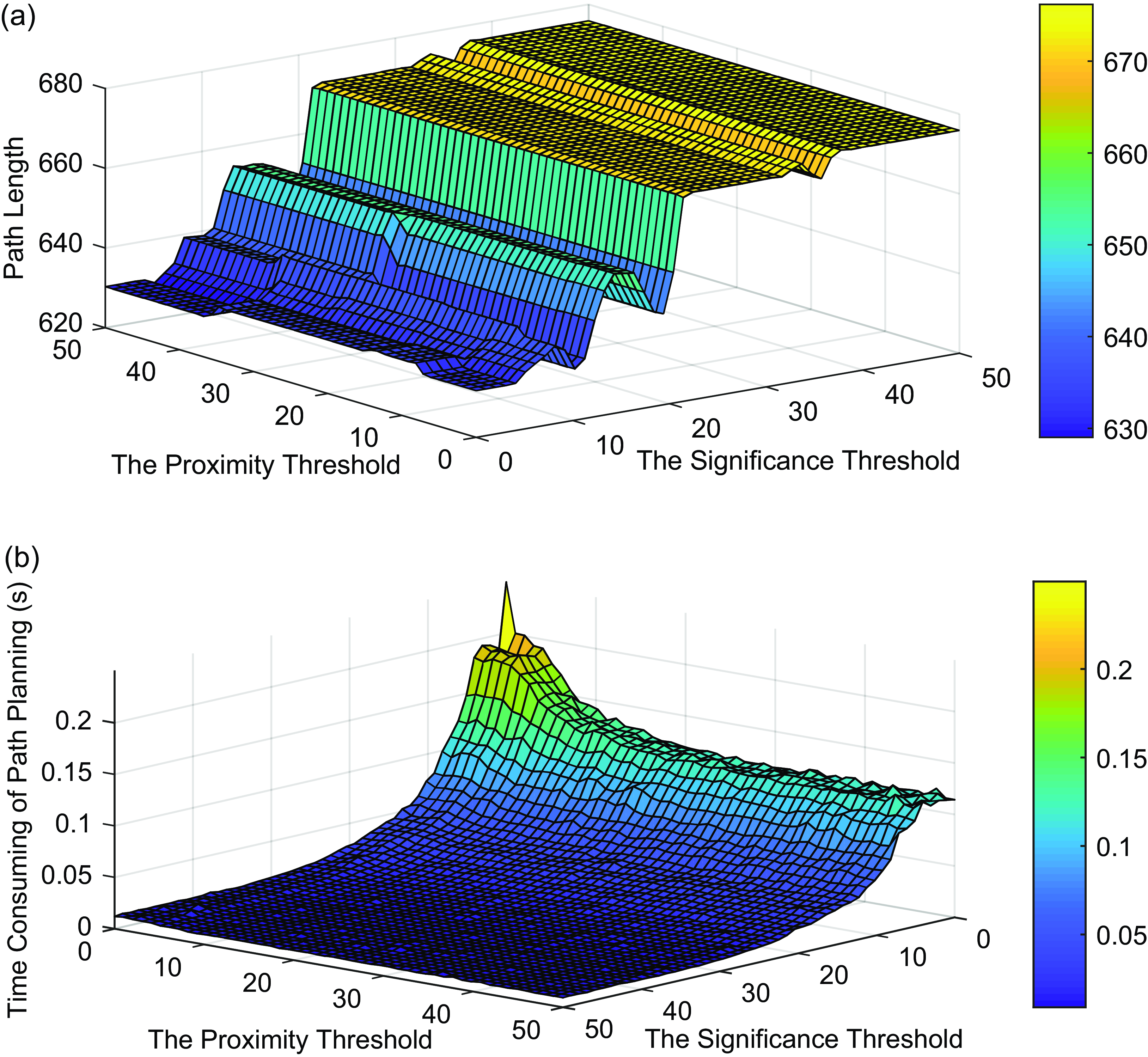
are selected in every 1 unit from 1 to 50. The path length and time consumption of planning under different
 $\mu _s$
and
 $\mu _p$
are shown in Figure 7(a) and Figure 7(b). With the increase of the Significance Threshold, more cyclic connection is removed and the distribution of cyclic connection turns sparse, resulting in a lower ability for optimal searching but faster planning. A smaller Significance Threshold leads to a better optimal path, but the iterative time consumption rises. When the Significance Threshold is large, the Proximity Criteria has less impact on the optimal process, because few cyclic connection is left to enter the Proximity Criteria screening. The smaller the selected Proximity Criteria, the more optimal the path becomes; however, this also results in increased time consumption. However, the impact of the Significance Threshold is much more significant than the Proximity Criteria in general.
4.3. Comparative simulation in dynamic environments
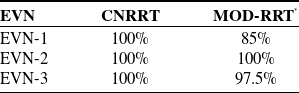
The rate of successful navigations in 40 repeating tests.

The simulation results about cyclic connection. (a) The length of the path generated with various Significance Threshold and Proximity Criteria. (b) The time consumption of planning with various Significance Threshold and Proximity Criteria.

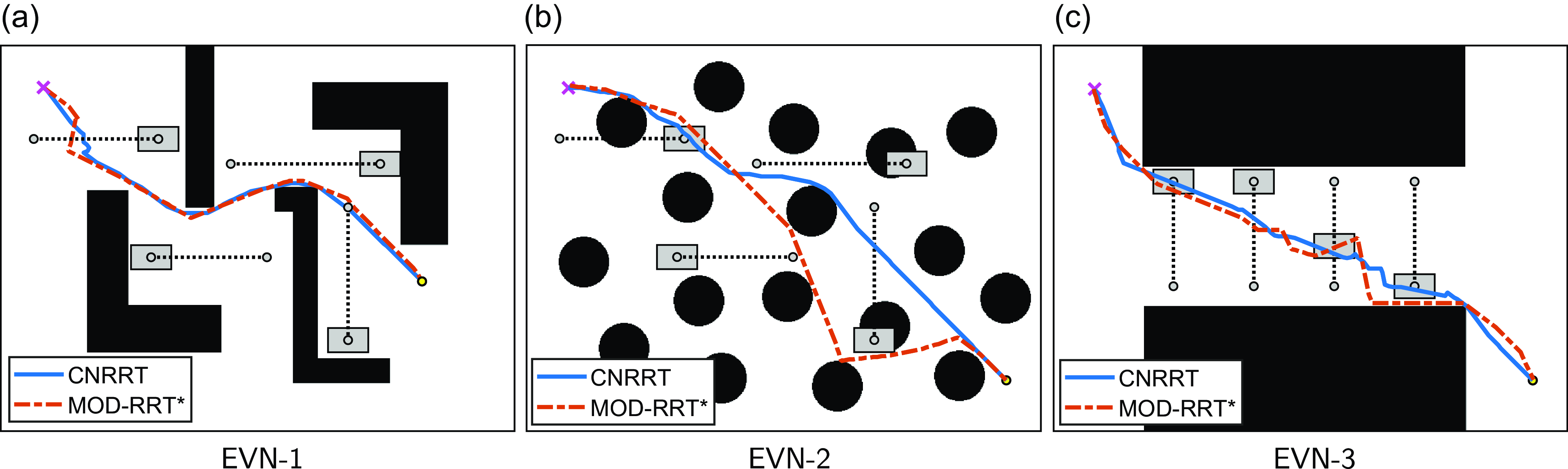
The state-of-the-art path planning method in dynamic environment, MOD-RRT*, is selected to compare with the CNRRT method. Three different environments (EVN-1, EVN-2, and EVN-3) with four mobile obstacles are built. The moving obstacles reciprocate in straight lines at a constant speed, and the moving speed is 3 pixels per frame. The two methods adjust the robot path in real time according to the changes in the environment. Starting from the initial location, the robot moves along the paths at the speed of 5 pixels per frame. The moving trajectory is recorded until the robot arrives at the destination. The key parameters of CNRRT are set as follows:
 $\mu _s=8$
,
 $\mu _p=6$
, and
 $\mu _{mc}$
is
 $0.75\%$
of the area of
 $X_{free}$
. Forty times of navigation are executed to test the two methods. The rate of successful navigation in 40 repeating tests is listed in Table I. The CNRRT method achieves
 $100\%$
successful rate in three environments. The MOD-RRT* method fails to complete navigation in environments 1 and 3. Because there are no valid nodes in the neighborhood area of the breakpoint, MOD-RRT* fails to reconnect the disconnected branch to rebuild a new path. The CNRRT shows higher reliability in three environments than MOD-RRT*.
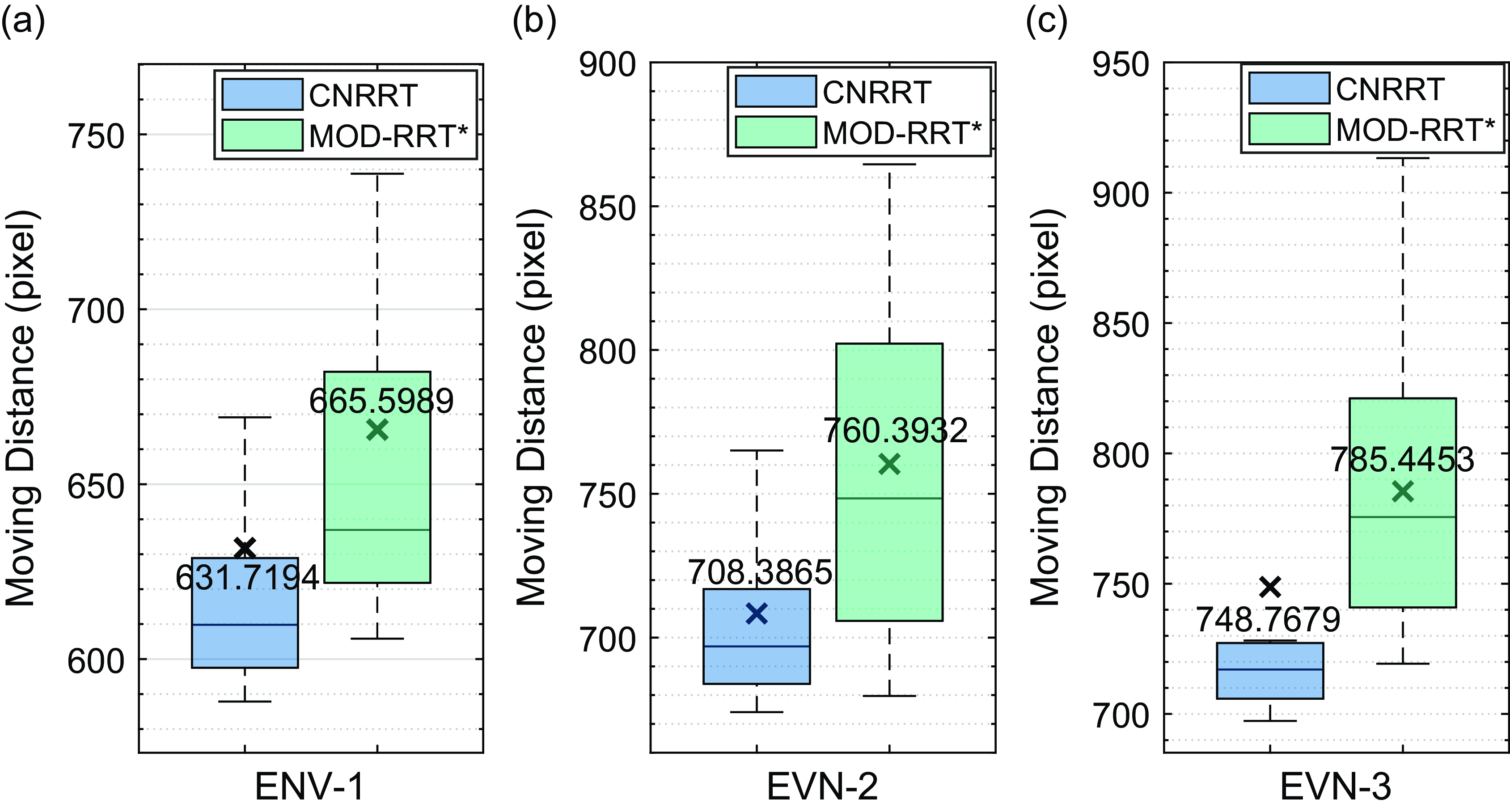
The moving trajectories of robots under the two methods in three environments are shown in Figure 8. The fluctuation of the overall trajectory after navigation accomplishment is smaller under the guidance of CNRRT, which shows that CNRRT has a better path selection strategy in the face of dynamic obstacles. The compared result of the moving distance of the robot and replanning time consumption are shown in Figures 9 and 10. The distribution of 40 tests of CNRRT outperforms the MOD-RRT* in both path length and replanning time among three environments. For moving distance, the CNRRT achieves
 $5.09\%$
,
 $6.84\%$
, and
 $4.67\%$
shorter trajectories in three environments on average than the MOD-RRT* method. For time consumption, the CNRRT takes
 $30.90\%$
,
 $32.85\%$
, and
 $32.22\%$
less time in three environments than MOD-RRT* to replan the path in the dynamic frame. The CNRRT method is efficient with low computing consumption and high stability to search for the optimal path in real time.
The moving trajectories in three dynamic environments under the CNRRT planner and the MOD-RRT* planner. The black blocks represent the static obstacles, while the gray rectangles represent the moving obstacles. The gray points are the endpoints of the reciprocating motion of moving obstacles.

The comparison simulation results about moving distance between CNRRT and MOD-RRT*. The cross marks with numbers represent the mean value.

The comparison simulation results about replanning time-consuming between CNRRT and MOD-RRT*. The cross marks with numbers represent the mean value.

The PRM method with the replanning process is compared with the CNRRT method to test the two different road nets of the methods. Different proportions of space occupied by obstacles, 10%, 15%, 20%, 25%, and 30%, are set on the randomly generated map. The result is shown in Figure 11 and Figure 12. Among the five types of maps, the CNRRT guides the robot to move along a better trajectory (8.12% shorter on average) with faster replanning speed (24.62% less time consumption on average) to the moving obstacle than PRM. When the proportion of the obstacle area is large, as 30% in the test, it takes much more replanning time for the PRM method to obtain a high-quality path. The road net of PRM is built by connecting sampling points in the map, rather than the growth pattern from the root node. The dense obstacle leads to a fragmented map, which causes disconnected sampling points in PRM. More sampling points and pairwise connections are generated to ensure the connection of the road net, which increases the computational burden on collision detection and path search. CNRRT utilizes the growth pattern to cover the map, and a single connection between two nodes greatly reduces the complexity of the road network, which achieves a stable computing speed.
The ablation test about the cyclic connection is conducted between CNRRT and ACNRRT. Compared with CNRRT, the ACNRRT method has the map-covered tree and branch prune, reconnection, and regrowth mechanism, but no cyclic connection. The compared result is shown in Figure 11 and Figure 12. CNRRT realizes a much better movement trajectory within the efficient time consumption. With the cyclic connection, the path length of CNRRT is reduced by 23.21% on average compared to ACNRRT.
The MOD-RRT* method is compared with CNRRT in a random map. The movement trajectory length and the replanning time consumption of CNRRT are 11.90% and 24.74% less than MOD-RRT*.
The movement distance of CNRRT, PRM, ACNRRT, and MOD-RRT* method in random maps with moving obstacles. The cross marks represent the average values.

The replanning time consumption of CNRRT, PRM, ACNRRT, and MOD-RRT* method in random maps with moving obstacles. The cross marks represent the average values.

4.4. Long-term simulation in dynamic environment
The performance of the CNRRT method in a long-term running situation is tested. The EVN-1 with the same moving obstacles is utilized in this simulation. Ten destinations in sequence are set to the robot in order. When the robot arrives at one destination, the next is given to the robot immediately. The quality of paths is measured by the relative deviation from the Theta* result
 $L_{theta*}$
in the same configuration space as follows:
 \begin{align} Q(L)=[len(L)-len(L_{theta*})]\setminus len(L_{theta*}). \end{align}
 $len(\cdot )$
is the Euclidean length of the path.
 $Q(L)$
of the dynamic planned path and the time consumption are calculated. The results are shown in Figure 13. The green vertical lines represent the frame that the next destination is given to the robot. The performance fluctuation
 $\rho$
is defined as the difference between the value at the target change frame and the mean value of all frames except the target change frame.
 $\rho$
of
 $Q(L)$
is
 $-0.0356 \pm 0.0359$
, and
 $\rho$
of the calculation time consumption is
 $10.9 \pm 14.9ms$
. During the 10 motion processes, the
 $Q(L)$
of path length fluctuates around 0 and has no significant change at the frame of destination replacement. The time consumption rises slightly (
 $13.57\%$
to the mean value of the time consumption) when a new destination is given, but the peak value is near 0.13 s, which still meets the requirement of real-time planning. The time consumption rise is mainly caused by the instant increase of node number of the path when the destination switches. As the robot gradually approaches the destination, the number of nodes contained in the path decreases, leading to less cost of collision detection and iterative optimization. The CNRRT method can deal with long-term task sequence without additional maintenance and significant performance degradation. Besides, the CNRRT has consistent optimization ability on start-end pairs with different directions on the map, which verifies the omnidirectional consistency of the CNRRT.
4.5. Real-world implementation
The real-world experiment is executed with a four-wheel independent driving robot with slip steering. A field with the size of 4.8 m
 $\times$
3.2 m is set. The experimental environment and the robot are shown in Figure 14. The moving obstacles are driven by the same type of robots inside the boxes. The maximum linear velocities of the robot and the moving obstacles are
 $0.5m/s$
and
 $0.3m/s$
, respectively. The obstacle boundaries are expanded according to the shape of the robot. Since the experiment uses a robot with nonholonomic constraints, the moving obstacle boundaries are further expanded according to the relative velocity between the moving obstacles and the robot. The pose of the robot and the two moving obstacles are estimated by the global vision through the ArUco Markers. The key parameters of CNRRT are set as follows:
 $\mu _s=8$
,
 $\mu _p=6$
, and
 $\mu _{mc}$
is
 $0.75\%$
. The snapshots of key frames in the experiment are shown in Figure 15. The blue line represents the motion trajectory of the robot. The robot bypasses the obstacle successfully when the two moving obstacles block the forward trajectory, which is shown in the
 $4$
th and the
 $7$
th frames in Figure 15.
Results of the real-world implementation.

The simulation result of the CNRRT method running in the long-term situation with destination sequence.

The experimental field and the robot.

The key frames of the real-world experiment of the CNRRT method. The location with the cross sign is the starting point, while the circle point represents the destination. The two blackish-green boxes with the ArUco Markers are moving obstacles, whose motion directions are represented as the blue lines with arrows. Other blackish-green boxes are static obstacles. The light green area is the expansion of obstacles according to the shape of the robot.

The navigation process is executed repeatedly for 10 times. The length of the motion trajectory and time consumption of the navigation process are shown in Table II. The CNRRT guides the robot to complete navigation with a shorter trajectory, which is
 $13.68\%$
shorter than the MOD-RRT*. For the navigation time consumption, the robot with the CNRRT planner uses
 $11.33\%$
less time to arrive at the destination than the MOD-RRT* planner. The real-world experiment verifies that the CNRRT efficiently guides the robot to move in a dynamic environment with optimal trajectory and avoid moving obstacles.
5. Discussion
From the simulation and experiment results, CNRRT shows efficient characteristics with near-optimality, real-time planning, and lifelong pattern. When the obstacle moves in a narrow channel (as the upper right moving obstacle in EVN-1), it is difficult for MOD-RRT* to reconnect the broken branch to the main tree only from the breakpoint, which leads to a drop in the success rate of MOD-RRT* in EVN-1. The CNRRT method reconnects the subtree to the main tree through random sampling, which aims at all of the nodes in the subtree and has a low computational cost. The CNRRT can switch the path direction in a wide range when the current path is completely blocked.
RRT* tree is based on the cost to the root node. High computational consumption is needed for rebuilding or rewiring the whole tree when running in the long-term scenario. The CNRRT generates a decentralized path network through the cyclic connection across the map. The path network is consistent for different directions of start-end pairs. When the starting point and the target change, the path network can be used directly for searching without transformation or a large scale of rewiring calculations.
For the efficiency of the CNRRT, through the cyclic connection, the planned path jumps out of the channel where it is located and enters other path clusters that have better quality. Meanwhile, the cyclic connection can improve the path locally and find a shorter one in homotopy path clusters. The fast path generation and the greedy-based iterative search are the important factors for the efficient searching ability of CNRRT.
The results from the CNRRT are near-optimal solutions. The node number of the map-covered tree and the cyclic branch is impossible to infinity in real scenes. More cyclic connection leads to a result with higher quality, but the more searching time it spends. From the result of moving distance and replanning time of the comparison simulation in Figure 9, the CNRRT method achieves a good balance between optimization and real-time planning.
The CNRRT method achieve autonomous navigation of robots in complex environments. It improves the independent working ability of the robot and reduces the dependence on human intervention, which leads to the lower management costs for operators. The CNRRT improves the adaptability to the environment of robot and reduces the requirement for work environment layout. The optimized path improves the work efficiency of robot and enhances production efficiency. The dynamic collision avoidance capability reduces the wear and tear of the robot, which reduces the maintenance costs.
6. Conclusion
In this article, we proposed a novel CNRRT method to generate the optimal real-time path in a dynamic environment. The cyclic branch was built to increase the richness of paths in the map-covered tree. A quick iterative searching strategy was proposed based on the acyclic edge, which avoided the huge cost of searching in the complex cyclic net. During the configuration space change, the effectiveness, connectivity, and uniformity of the path network were maintained. The probabilistic completeness was guaranteed. Compared with the state-of-the-art method, the CNRRT achieved a
 $5.53\%$
shorter moving trajectory of robot navigation and a
 $31.99\%$
reduction in replanning time. Meanwhile, the CNRRT had high performance in the long-term running scenario. The CNRRT method is an efficient and stable real-time optimization path planning method.
In the future study, we would extend the CNRRT as a high-dimensional space optimizer to solve the state transition trajectory planning problem of multi-agent systems.
Author contributions
Chen Zhang, Lelai Zhou, and Yibin Li conceived and designed the study. Chen Zhang and Lelai Zhou conducted data gathering. Yibin Li performed statistical analyses. Chen Zhang wrote the article.
Financial support
This work was supported in part by the National Natural Science Foundation of China under Grant 62373221 and in part by the Shandong Provincial Natural Science Foundation for Distinguished Young Scholars under Grant ZR2022JQ28.
Competing interests
The authors declare no conflicts of interest exist.
Ethical approval
Not applicable.