Introduction
Traditional metal alloying involves adding small amounts of secondary elements to a principal parent metal. Understanding of the resulting material properties is based on the resulting solid solution or presence of secondary phases. While there are many well-established, verified mechanisms for alloying effects in traditional metal alloys (e.g., dilute alloys), the physical mechanisms underlying material properties in alloys containing multiple principal elements are not yet understood. Such alloys, most commonly referred to in the literature as high entropy alloys (HEAs), display mechanical properties that can outperform traditional alloys.
Refractory body-centered cubic (BCC) HEAs have shown thermal stability and high-temperature strength retention comparable with and even exceeding super alloys.[Reference Senkov, Miracle, Chaput and Couzinie1–Reference Zhang, Zuo, Tang, Gao, Dahmen, Liaw and Lu6] Transmission electron microscopy of deformed samples suggests that primary deformation mechanisms in these alloys are both dislocations and mechanical twinning.[Reference Senkov, Scott, Senkova, Miracle and Woodward7] Twinning has also been suggested to contribute to increased ductility in BCC refractory equi-atomic TiNbMoTaW HEA[Reference Han, Chen, Zhao, Fan, Yang, Shao and Yao8] and an equi-atomic TaNbHfZrTi HEA.[Reference Senkov, Scott, Senkova, Meisenkothen, Miracle and Woodward2]
The face-centered cubic (FCC) equi-atomic CoCrFeMnNi HEA (also referred to as Cantor's alloy) has displayed increasing strength and ductility with decreasing temperature.[Reference Gludovatz, Hohenwarter, Catoor, Chang, George and Ritchie9] Dominant deformation mechanisms observed in FCC HEAs have been dissociated dislocation pairs and mechanical twins.[Reference Deng, Tasan, Pradeep, Springer, Kostka and Raabe10–Reference Laplanche, Kostka, Horst, Eggeler and George18] While mechanical twinning directly contributes a small amount to the total strain, twinning is the primary source of high strain hardening in HEAs[Reference Gludovatz, Hohenwarter, Catoor, Chang, George and Ritchie9, Reference Laplanche, Kostka, Horst, Eggeler and George18] due to the twin boundary acting as a barrier to dislocation motion as similarly observed in twinning-induced plasticity steels.[Reference Qin and Bhadeshia19–Reference Bouaziz and Guelton21]
These experimental results show that twinning plays an important role in the deformation of both FCC and BCC HEAs and the prevalence of twinning in HEAs is the source of some of their favorable mechanical properties. Twinning mechanisms in FCC metals are well-known, and considering the experimental observation of stacking faults in FCC HEAs, it seems reasonable that these mechanisms are responsible for twinning in FCC HEAs. It is not clear what mechanisms of deformation twinning are active in BCC HEAs and we are not aware of any experimental studies that report crystallographic information of deformation twins in BCC HEAs. It is therefore important to understand the atomistic details of twinning in BCC HEAs.
In this paper, we perform molecular dynamics (MD) simulations of compression of a representative BCC HEA nanopillar. We observe nucleation of mechanical twins from the surface as the dominant deformation mechanism in the BCC nanopillar under compression. We reveal the detailed formation mechanism of such twins and relate them to a previous theory of predicted BCC faults. We also present calculations of stacking fault and twinning energy curves in both representative FCC and BCC HEA and discuss the activation of twinning in HEAs in the context of alloying effects on the planar fault energy.
Methods
We employed molecular dynamics simulations to explore the nucleation mechanism of deformation twinning in a representative BCC HEA nanopillar under compression. To construct the initial sample, we created a cylindrical geometry with the axis aligned along the <001> crystallographic direction. This loading orientation was chosen because the resolved shear stress favors the twinning systems over dislocation systems and previous MD studies of high-symmetry compression of a BCC W nanopillar reported twinning as the dominant deformation mechanism.[Reference Wang, Zeng, Weinberger, Zhang, Zhu and Mao22] The initial sample was monatomic and the HEA was created by randomly replacing atomic species to achieve an equi-atomic composition. The dimensions of the cylinders were 30 nm in diameter with a length of 90 nm. The direction parallel to the cylinder axis was periodic and the two directions perpendicular to the axis were free surface boundaries. The energy of the initial structures was minimized following a conjugate gradient scheme. The system was then assigned a velocity profile corresponding to the simulation temperature of 50 K. The pillar was then equilibrated for 200 ps at the assigned temperature with zero pressure along the axial direction followed by equilibration for 200 ps under time integration of the constant particle, volume, and energy (NVE) ensemble. All simulations were performed using an integration time step of 1 fs. Compression was performed by deforming the simulation box at a strain rate of 108/s up to a total strain of 15%. Stacking fault and twinning fault energy calculations were performed on both a representative FCC and BCC HEA following standard methodology.[Reference Zimmerman, Gao and Abraham23] We implemented the embedded atom method (EAM) with an interatomic potential developed by Zhou et al.[Reference Zhou, Johnson and Wadley24] and chose the equi-atomic CoFeNiPd system as our representative FCC HEA and the equi-atomic AlMoWTa system as our representative BCC HEA. These alloys were chosen based on the availability of interatomic potentials and similarity to experimentally-reported alloys although it should be noted that because these potentials have not been verified extensively, they may not be robust representations of these alloys, but serve as general models. We do note that this potential has been used in previous molecular dynamics simulations of HEAs, notably the FCC Co30Fe16.67Ni36.67Ti16.67 where they report reasonable values of critical resolved shear stress (CRSS) for dislocation motion as compared with experimental measurements on the Cantor alloy.[Reference Rao, Woodward, Parthasarathy and Senkov25] All simulations were performed using the LAMMPS molecular dynamics software,[Reference Plimpton26] and OVITO[Reference Stukowski27] was used for common neighbor analysis, calculation of atomic shear strain, and visualization.
A block with dimensions 12.5 × 12.5 × 20 nm3 with equi-atomic composition was constructed and relaxed. The energy of this initially-relaxed structure was taken as the reference energy. The stacking fault plane was perpendicular to the z-axis, which is prescribed by a free surface boundary condition and the two perpendicular directions were prescribed by periodic boundary conditions. For the FCC HEA, the stacking fault plane was (111) and the displacement direction was  $[11\bar{2}]$. For the BCC HEA, the stacking fault plane was
 $( {11\bar{2}} ) $ and the displacement direction was
 $[\bar{1}\bar{1}\bar{1}]$. The top half of the block was displaced in the fault direction by a fraction of the Burgers vector and the total energy was calculated while keeping the atoms fixed. This was repeated along the entire length of periodicity in the fault direction. In order to generate the twinning fault energy curves for the representative FCC HEA following a displacement of
 $(a/6 )\langle112\rangle$, the plane adjacent to the originally displaced (111) plane was displaced incrementally until a total displacement of
 $(a/6 )\langle112\rangle$. This resulted in a three-layer twin configuration in the FCC HEA. In order to generate the twinning fault energy curves for the representative BCC HEA, we followed the mechanism as observed in our nanopillar compression simulations (discussed in detail below). We first generated a
 $(a/3)\langle\bar{1}\bar{1}\bar{1}\rangle$ fault followed by a second
 $(a/3)\langle\bar{1}\bar{1}\bar{1}\rangle$ fault that was two atomic planes above the first fault. We then applied a
 $(-a/6)\langle\bar{1}\bar{1}\bar{1}\rangle$ fault along the plane between these two faults to generate the three-layer twin configuration. The planar fault energy was calculated as the difference between the computed energy and reference energy, normalized by the area of the cross-section: γ = E − E 0/A. This resulted in the unrelaxed stacking and twinning fault energy curve. The relaxed planar fault energy curves were computed following this same methodology, but allowing atoms to relax in the direction perpendicular to the faulted plane.
Results
Deformation mechanism in BCC HEA nanopillar
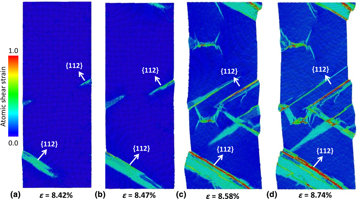
Figure 1 is a sequence of images showing the initial plastic deformation process of the representative BCC HEA. Atoms are colored by their atomic strain. Figure 1(a) shows that plastic deformation occurs via nucleation of groups of adjacent sheared atomic planes from the surface. Sheared planes are perpendicular to the {112} planes and show a displacement along the <111> direction. Due to the high symmetry of the (001) loading, several slip systems are activated. These groups of sheared planes propagate through the pillar until encountering an intersecting sheared region or the opposite pillar surface. We also observe some cross-slip onto symmetric {112} planes [as seen in Fig. 1(c)]. Inspection of the atoms in these regions indicates that they are in a twinned orientation with respect to the parent lattice. Upon further straining, we observe more cross-slip and thickening of twinned regions. We also observe the presence of full dislocations in the deformed pillar that originate from the twinned regions but not from the pillar surface.
A sequence of images taken from compression of a representative BCC HEA nanopillar at initial plastic deformation. Atoms are colored by atomic strain. (a) shows that deformation proceeds via nucleation of partial dislocations from the surface around 8.42% strain. (b) These partial dislocations grow into sheared regions as more partials nucleate adjacently and propagate through the diameter of the pillar. (c) At 8.58% we observe the activation of multiple slip systems. (d) Inspection of sheared regions in the final snapshot indicates a twin configuration with respect to the original parent crystal.

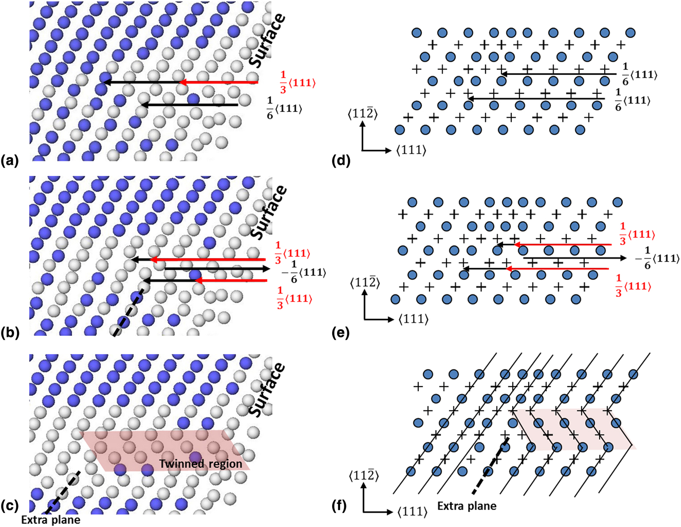
A closer inspection of the nucleation source of these sheared planes indicates the presence of several (a/6)〈111〉 partial dislocations lying on {112} planes. An example configuration of snapshots taken from simulation and corresponding schematic is shown in Fig. 2. These (a/6)〈111〉 partial dislocations are present at several locations across the entire pillar surface, most likely corresponding to regions of favorable chemical concentration.[Reference Smith, Hooshmand, Esser, Otto, McComb, George, Ghazisaeidi and Mills12, Reference Liu and Wei28]
(a)–(c) are snapshots from nanopillar compression simulations showing the formation of a twinned region. Following common neighbor analysis, atoms colored blue indicate a BCC crystalline structure and grey atoms have a local neighborhood that does not correspond to any crystal structure. (d)–(f) are schematics that correspond to the shearing sequence shown in (a)–(c). Filled circles correspond to atoms lying in the plane of page while crosses correspond to the adjacent atomic layer below. Black arrows indicate a (a/6)〈111〉 partial dislocation and red arrows indicate a (a/3)〈111〉 partial dislocation. We find the presence of several (a/6)〈111〉 partial dislocations along the surface of the nanopillar as shown in (a). Further shearing results in a configuration of two (a/3)〈111〉 partial dislocations separated by one atomic plane. A shear displacement of (−a/6)〈111〉 along the plane separating these two (a/3)〈111〉 partial dislocations [shown in (b) and (e)] results in a twinned stacking sequence. The resulting twinned region is highlighted in (c) and (f) and the resulting extra plane is indicated by the dashed line. Solid black lines in (f) show twinned atomic columns.
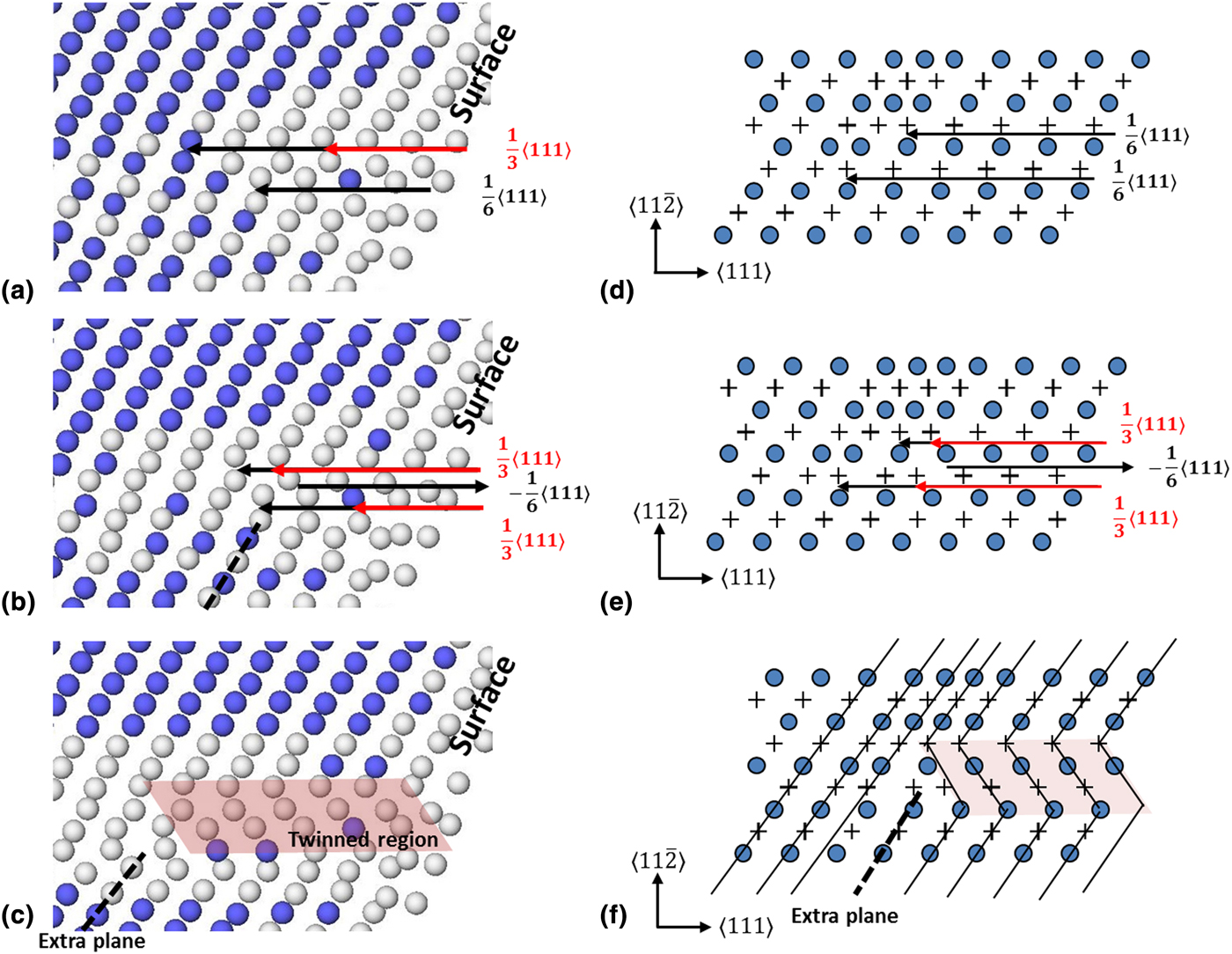
In the BCC lattice, stacking faults are stable on the {112} planes, which are also known as the coherent twin planes in the BCC lattice.[Reference Hirth and Lothe29, Reference Christian and Mahajan30] Such faults can be created by the glide of partial dislocations on the {112} planes. From a perfect (a/2)〈111〉 dislocation on the {112} plane, dissociation can produce (a/3)〈111〉, (a/6)〈111〉, and (a/12)〈111〉 partial dislocations. Figure 2(a) shows an example of several (a/6)〈111〉 partial dislocations emanating from the surface of the pillar (black arrows). Figure 2(b) also shows that subsequent (a/6)〈111〉 partials can nucleate on existing faulted planes, which results in a total (a/3)〈111〉 shearing (red arrows). No trailing partials are observed to nucleate from the surface, which leaves stable extended stacking faults.
Formation of a twinned region requires the presence of two (a/3)〈111〉 partial dislocations separated by one atomic plane. These can form from (a/6)〈111〉 shearing of existing (a/6)〈111〉 partial dislocations. An example of existing (a/6)〈111〉 partial dislocations is shown in Fig. 2(d). A shear displacement of (−a/6)〈111〉 along the plane separating these two (a/3)〈111〉 partial dislocations [Fig. 2(e)] results in a twinned stacking sequence [twinned region highlighting in Fig. 2(f)]. A schematic of the formation of partial dislocations that comprise this twinned region and the resulting twinned configuration are shown in Figs. 2(d)–2(f). The presence of these partials and formation of twinned region occurring in our MD simulations analogous to Figs. 2(d)–2(f) are shown in Figs. 2(a)–2(c). The combination of two (a/3)〈111〉 partial dislocations and one (−a/6)〈111〉 partial dislocation gives this configuration a total displacement of (a/2)〈111〉, which is reflected in the extra plane shown in schematic Fig. 2(c). This mechanism is similar to the I3 fault where a (a/2)〈111〉 dislocation has dissociated into three (a/6)〈111〉 dislocations, each separated by one atomic plane[Reference Hirth and Lothe29, Reference Lagerlöf31] and multilayer stacking faults in BCC metals.[Reference Vítek32] However, there is an important distinction: All displacements in these mechanisms occur along the twinning direction; in contrast, the twinning mechanism observed here is facilitated by a set of {112} planes displaced in the twinning and anti-twinning direction.
Stacking and twinning fault energy
The proposed BCC twinning mechanism here is dependent upon the formation of successive, adjacent stacking faults. Similarly, the formation of mechanical twins in FCC is known to be facilitated by the formation of successive adjacent faulted planes and thus dependent upon stacking fault energy.[Reference Hirth and Lothe29, Reference Van Swygenhoven, Derlet and Frøseth33, Reference Asaro and Suresh34] To better understand the stacking fault energy of our HEA systems, we calculated the unrelaxed and relaxed stacking fault and twinning fault energy curves for our simulated FCC and BCC HEAs and all combinations of their constituent elements.
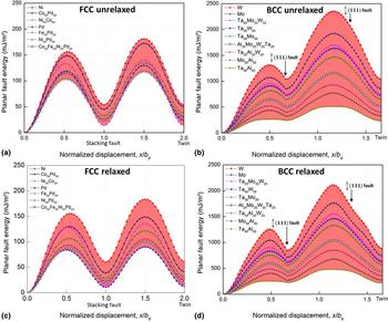
Figure 3 shows the stacking fault and twinning energy curves for our representative FCC and BCC HEAs and a selection of their constituent pure metals and alloys. Figures 3(a) and 3(b) show the unrelaxed planar fault energy curves while Figs. 3(c) and 3(d) show the relaxed planar fault energy curves. We first describe the effects of alloying on the stacking and twinning fault energy curves in HEAs and compare them with their component alloys, and then we discuss the effects of local concentration differences on the energy barriers for the formation of stacking faults and twins.
The unrelaxed stacking fault and twin fault energy curves for (a) a representative FCC and (b) a representative BCC HEA along with a selection of alloys constructed from combinations of constituent elements. The relaxed energy curves for the representative FCC (c) and BCC (d) HEAs along with a selection of alloys constructed from combinations of constituent elements.
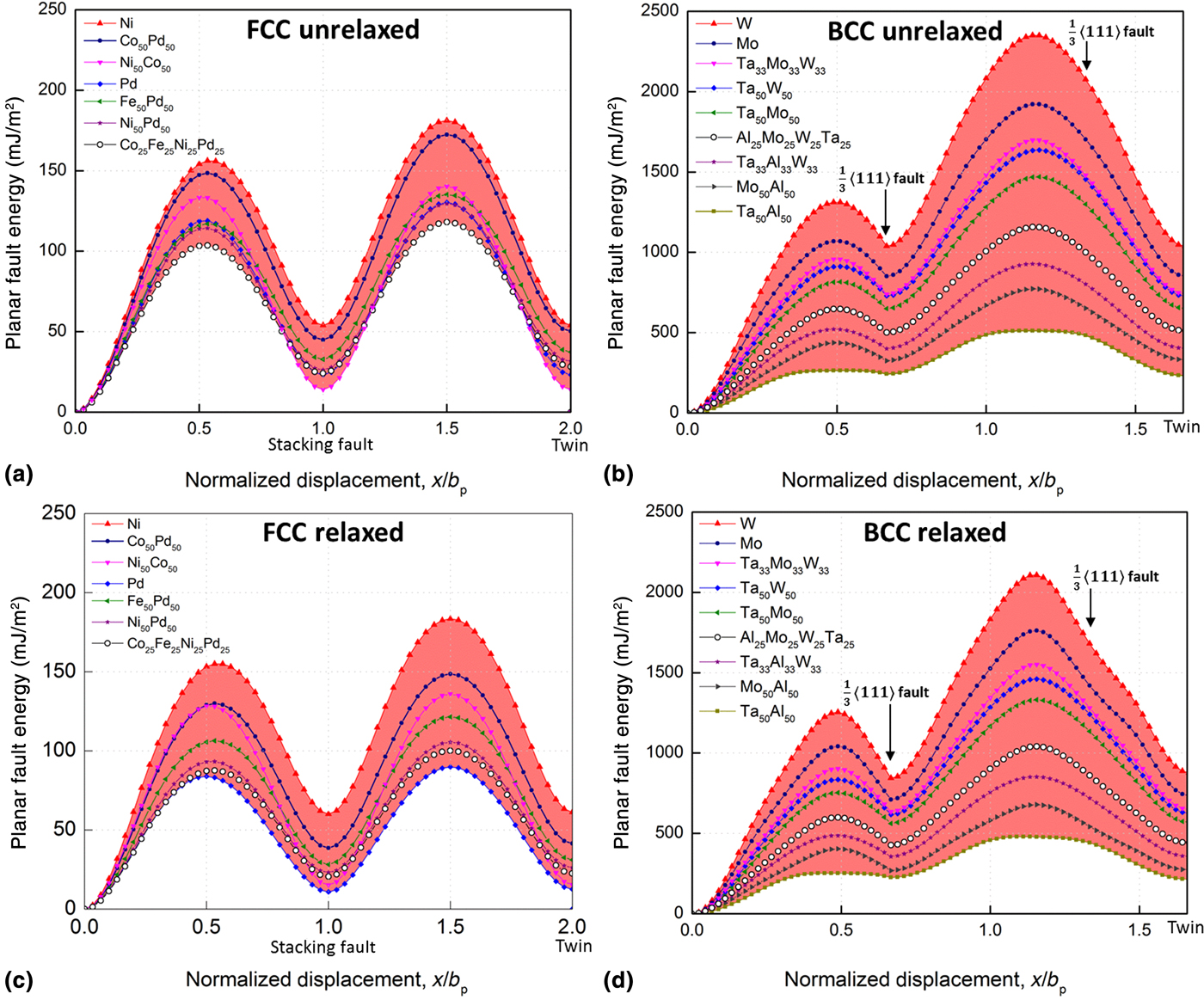
The first peak in Fig. 3(a) corresponds to the energy barrier to create a 〈112〉/{111} stacking fault in the FCC HEA while the second peak corresponds to the energy barrier to create an adjacent fault giving a three-layer twin. The first and second minima correspond to the stable stacking fault and twin configurations. The energy barriers of the FCC HEA show the lowest values out of all stable FCC alloys and the stable stacking fault and twin energy of the FCC HEA are also among the lowest of the stable FCC alloys.
Figure 3(b) shows the unrelaxed stacking and twinning fault energy curves of our representative BCC HEA. The first local maximum in Fig. 3(b) represents the energy barrier to form the first (a/3)〈111〉 stacking fault. The second maximum represents the energy barrier to create the second (a/3)〈111〉 stacking fault in the presence of the first fault. The formation of the (−a/6)〈111〉 fault into this configuration always results in a decrease in energy. The pure BCC elemental curves show very high energies to form stacking faults and twins. Increasing alloying tends to result in a reduction of fault energy. The HEA fault energy curve displays among the lowest energy among all BCC alloys. Both HEA energy barriers are approximately half the values of the same peaks in BCC W.
The relaxed planar fault energy curves shown in Figs. 3(c) and 3(d) show a general decreasing trend as compared with the unrelaxed energy curves. It should be noted that the planar fault energy of both the FCC and BCC HEA is not simply the weighted average of the planar fault energies of their constituent elements. In Fig. 3, we have only included planar energy curves for alloys that energetically favor the respective crystal structures. The local composition within the HEA, however, varies across all possible combinations of constituent elements. The shaded regions in Fig. 3 demonstrate the range of possible planar fault energies for stable crystal structures, highlighting the importance of treating the planar fault energy as a variable in HEAs. The stochastic nature of the cross-slip activation energy has also been observed in atomistic calculations in FCC solid solutions.[Reference Nöhring and Curtin35] We have also computed constituent alloys that show negative planar fault energies, which will further promote the ease of forming stacking faults and twins in these HEAs. These alloys are not included in Fig. 3 because their crystal lattices are energetically unfavorable.
Discussion
Previous studies have suggested that the propensity for forming extended stacking faults versus formation of full dislocations in several FCC metals depends on the ratio between the unstable stacking fault energy (energy barrier to form a stacking fault) and the stable stacking fault energy.[Reference Van Swygenhoven, Derlet and Frøseth33] When these two values are similar, the energy barrier to nucleate the trailing partial (and thus a full dislocation) is low. Similarly, the propensity for forming twins in FCC metals should also depend on the ratio between the unstable twin fault energy and the unstable stacking fault energy.[Reference Van Swygenhoven, Derlet and Frøseth33, Reference Tadmor and Hai36] When these two values are similar, the energy barrier to nucleate a trailing partial (thus forming a full dislocation) is similar to the energy barrier to nucleate an adjacent leading partial (thus forming a twin). The ratio between the unstable twin fault energy and unstable stacking fault energy of the HEA curve in Fig. 3(a) is 1.14, which is comparable with other FCC systems in Fig. 3(a). Specifically Ni, Pd, Ni50Fe50, Ni50Pd50, and Ni33.3Co33.3Pd33.3, have ratios of 1.16, 1.10, 1.16, 1.13, and 1.14, respectively. The energy barrier to form a twin is thus always greater than the energy barrier to form a stacking fault in our FCC alloys.
Twinning has been experimentally observed in refractory BCC HEAs[Reference Senkov, Scott, Senkova, Miracle and Woodward7] and has been suggested to promote increase ductility in some systems.[Reference Senkov, Scott, Senkova, Meisenkothen, Miracle and Woodward2, Reference Han, Chen, Zhao, Fan, Yang, Shao and Yao8] The surface nucleation mechanism observed in these initially-pristine nanopillars here is not likely the dominant mechanism in these experimental studies. It is reasonably expected that other defects, such as grain boundaries, might also serve as possible nucleation sites for twin nucleation in BCC HEAs. Twin nucleation from a phase boundary has been observed in simulations that will be the subject of future reports and is of interest to multiphase HEAs. Our calculations of planar fault energy do suggest that partial dislocations and twins are energetically easier to form in the HEA as compared with the pure constituent elements. Although twinning has been reported in molecular dynamic simulations of W nanopillars under the same crystallographic orientation, no information regarding the atomic structure of the twin embryo was provided, making it difficult to compare against our observations.[Reference Wang, Zeng, Weinberger, Zhang, Zhu and Mao22] Although we cannot find literature descriptions of the exact twin mechanism that we observe, it seems reasonable that this mechanism could occur more generally in BCC alloys. What is unique to HEAs is the statistical nature of planar fault energy demonstrated by the shaded area in Fig. 3.
It is important to note that each curve in Fig. 3 represents a fixed alloy composition. For the cross-sectional area studied here, these values represent averaged bulk quantities. At short length-scales, the local composition within the HEA will more closely represent a non equi-atomic composition and the planar fault energy will vary within the shaded regions of Fig. 3. We then expect that there will be regions with favorable (or unfavorable) local composition that will have a greater (or lower) likelihood to nucleate a stacking fault or twin. In our AlMoWTa HEA, local compositions that favor a FCC crystal structure could promote the BCC twinning mechanism proposed above. Two 1/3<111> stacking faults separated by a single {112} plane [refer to Fig. 2(b)] results in a local FCC stacking sequence. Favorable local compositions would then promote the formation and stabilize the configurations shown in Figs. 2(a) and 2(b). Previous studies have attempted to define a local stacking fault energy parameter and found that the stacking fault energy of a FCC Ni54Fe20Cr26 alloy has a standard deviation 158% of the mean value, clearly indicating regions within the FCC alloy can favor a non-FCC stacking sequence.[Reference Smith, Hooshmand, Esser, Otto, McComb, George, Ghazisaeidi and Mills12]
Conclusion
Here we have reported molecular dynamics simulations on nanopillar compression of a representative BCC HEA. These simulations show that surface nucleation of partial dislocations that form twinned regions are the dominant deformation mechanism in this material under compression along high-symmetry crystallographic directions. Following the observation of these partial dislocations, we propose a twin formation mechanism that involves partial dislocations gliding on adjacent atomic planes. It is expected that the same nucleation mechanism could occur at other defect sites inside BCC HEAs, such as grain or phase boundaries. To understand the prominence of twinning and stacking faults observed in HEAs, we calculate the stacking and twin fault energy curves for all elemental combinations of a representative FCC and BCC HEA. We show that in general, the HEA curves display lower energy as compared with their pure elemental constituents. These calculations also show that planar fault energies in HEAs can have a wide variation depending upon local atomic concentration. Future work would benefit greatly from crystallographic information of active deformation twinning systems in BCC HEAs as well as incorporation of the heterogeneity of planar fault energy in HEAs. Such understandings would help guide the design of novel HEAs that display enhanced strength and ductility through control of active twinning systems.
Acknowledgments
The authors gratefully acknowledge the financial support from the Agency for Science, Technology and Research (A*STAR) through Grant No. A1898b0043, and the use of computing resources at the A*STAR Computational Resource Centre, Singapore.