Introduction
The optically controlled reconfiguration technology is a combined technology of optical and electrical fields because it reconfigures the characteristics of the antennas and the operating bands of the filter circuits through switches. The new trend of wireless optical technology is smart lighting and the internet of things. In this technology, multiple electronic devices and smart LED bulbs can be controlled through a common cloud. The ON and OFF state of the LED bulbs are utilized to change the frequency and radiation pattern of the antenna. If these antennas are connected to the electronic devices that can be in contact with some other wireless frequency applications by the smart control of the LED bulbs without connecting any additional devices.
The most common multiband and frequency reconfiguration techniques with PIN and varactor diode switches and lumped elements have been presented in [Reference Cui, Zhang and Chen1–Reference Li, Nan, Liu and Tao4]. An optical receiving antenna has been developed with a multiband radio frequency transceiver for visible light and optical wireless communications [Reference Peng and Kong5, Reference Borges, Sodré and Rodovalho6]. An antenna was introduced with a low power optical switch for X-band applications [Reference Vian and Popovic7]. In this antenna, optically controlled SPDT switches are used to route the RF signal into the antenna. A stub loaded frequency reconfigurable antenna has been developed with photoconductive switches [Reference Pendharker and Shevgaonkar8]. The total frequency shift achieved by this antenna is 0.3GHz. Two 0.3mm thickness silicon switches were controlled by an 850 nm optical signal to reconfigure the frequency from 28 to 38 GHz in [Reference da Costa, Spadoti, Sodré, da Silva, Rodriguez, Puerta, Olmos and Monroy9] and their modulation scheme was discussed in [Reference da Costa, Arismar Cerqueira, Spadoti, da Silva, Ribeiro and Barbin10]. An optically controlled phased array antenna system with true-time delay devices [Reference Konkol, Ross, Shi, Harrity, Wright, Schuetz and Prather11] and an optically feeding array antenna has been developed with high power photodiodes for frequency reconfiguration [Reference Yegnanarayanan and Jalali12]. Next a slotted circular waveguide antenna at 5.8 GHz with 10% bandwidth and an E-shaped patch antenna at 2.4 and 5.8 GHz with a return loss of −12 dB and −40 dB respectively has been reported for Wi-Fi applications. In both cases, silicon dies and PIN diodes are used as switching elements [Reference da Cost, Cerqueira, Reis, Spadoti, Moreira Neto, Sapucaí and Indústria13, Reference Ullah, Ullah, Ahmad, Khan, Ahmad, Habib, Albreem, Alsharif and Uthansakul14]. More optically controlled antennas have been developed for frequency reconfiguration, Impedance tuning and cognitive radio applications. The operative frequency of the antennas are (2.26 to 3.15 GHz), (100 MHz to 40 GHz) and (3.1 to 10.6 GHz) respectively. All of the above cases used silicon die switches that were activated by a 980nm optical fiber [Reference Zhang, Lin, Yu, Liu and Denisov15–Reference Zhao, Lan, Han, Liang, Zhang and Wang17]. A planner 150 × 200 mm2 yagi-uda antenna was demonstrated for pattern reconfiguration with 2 PIN photodiodes. The maximum of 6.3 dbi gain was demonstrated in [Reference Panagamuwa and Chauraya18]. An optically controlled antenna is presented with a commercially available photodiode and phototransistors for reconfiguration [Reference Patron, Daryoush and Dandekar19]. The selected wavelength ranges for the above cases are 850 to 1550 nm.
In this paper, a novel optically controlled frequency diversity antenna is proposed for wireless applications. The proposed antenna is a compact, high gain; small dimension and multiband (4-bands) antenna compared with the reference antennas in Table 1. The photodiode switches were activated by optical fiber cables in the previous works. But in this work, two commercially available photodiodes are used for switching and they are activated by an LED bulb. If these antennas will be connected in aircraft landing systems at 4.3GHz it can reconfigure their frequency to wireless LAN and 5 G applications by the smart control of the LED bulbs without connecting any intermediate devices.
Proposed antenna comparison with reference (lit.) antennas

Antenna design techniques
Antenna structure
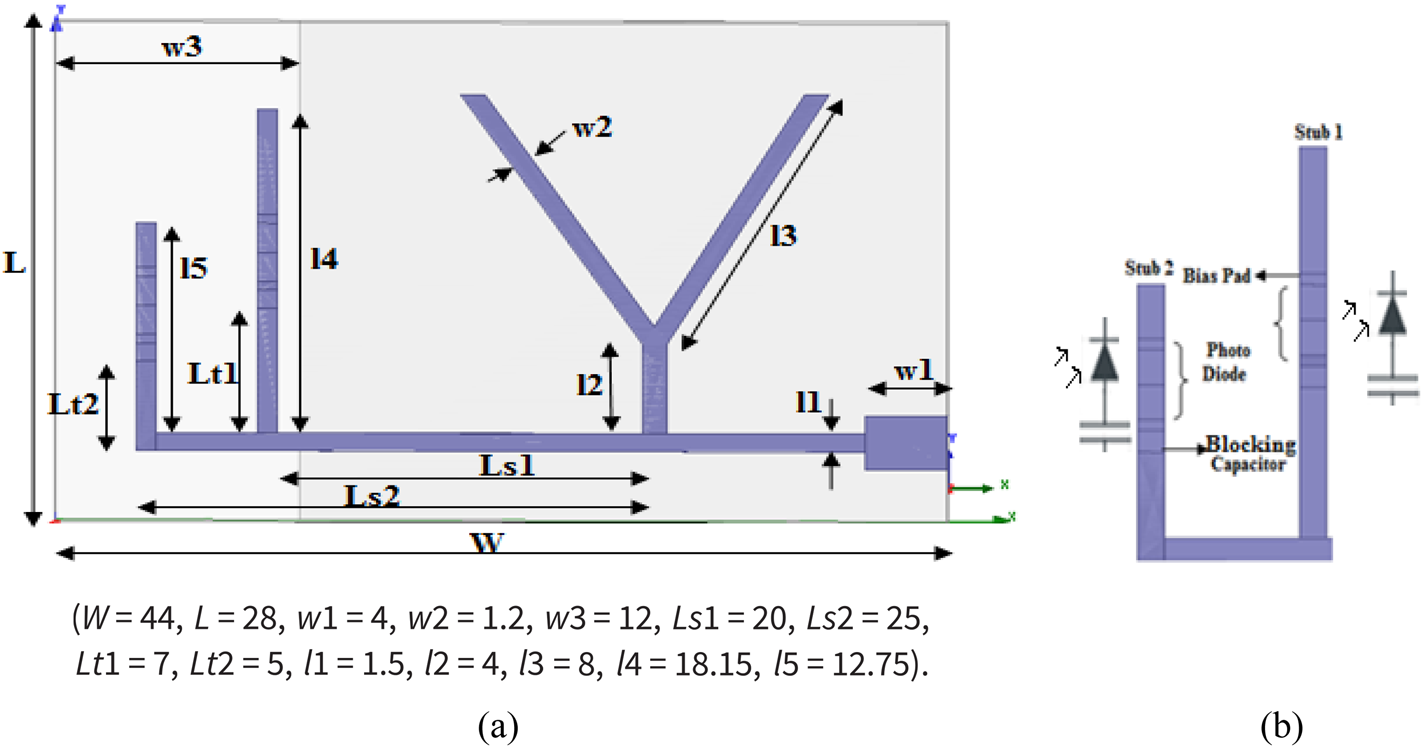
The proposed antenna is designed on Roger RO3003(tm) substrate with a substrate thickness of z = 1.52 mm, the permittivity of εr = 3.3 and the loss tangent of 0.0013. This antenna is a long wire V antenna model [Reference Reji and Manimegalai20]. Two 8mm length and 1.2mm width legs are arranged in the shape of V with one end of the V-shape is connected to the feeding stub and the next end of the wire is left to be opened. The length of the legs is calculated by λ/4 < (2× l3 + l2) < λ/2 (f o = 4 GHz, 2 × l3 + l2 = 2 × 8 + 4 = 20 mm).
The center frequency of the V-shaped radiator f o = 4GHz and the length of the feeding stub is λ/2. Two 14.4 mm(λ/4) and 9.5 mm(λ/8) length and 1mm width open-circuited stubs are connected perpendicular with the feeding stub. 4 mm length and 1.2 mm width photodiode switches [Reference Reji and Manimegalai20] are placed along with 2 pf blocking capacitors on the perpendicular stubs. The ground area of the substrate is reduced to 32 mm for increasing the gain of the antenna. The antenna structure and their stub arrangement with photodiodes are illustrated in Figs 1(a) and (b).
(a) Antenna with dimensions in mm (b) Antenna Stub arrangements.

Calculation of tuning stubs
The antenna design can be explained by a simple transmission line model with a stub tuning method. The stubs are located first at Y IN/G o = 1 position then the location will be adjusted by the equation (1). The lengths of the tuning stubs are calculated by equations (2)–(5). The effective lengths of the stubs are decided only by the conductivity of the photodiode switches. When the photodiodes are in OFF condition the conductivity G → 0, l ef1 and l ef2 = 0, then the value of l 4 = lt 1 and l 5 = lt 2. The relationship between lt 1, lt 2 and l ef1 and l ef2 are given in Fig. 4. When the photodiodes are in ON state the value of G is changed according to equation (2) and it changes the effective length of the stubs. If the antenna stub lengths are changed their resonant frequency is also changed from f o to some other value. The variations of G is calculated from the input admittance equation Y IN = G + Jωc.


Yr → Load Admittance β → 2π/λ(phase constant)
G → Conductance l ef → Effective length of the stubs
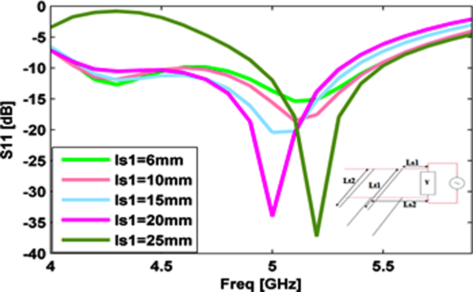
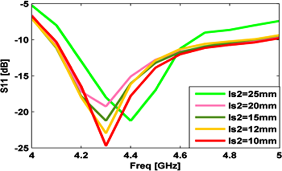
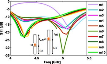
A Parametric study is done for finding the location of the stubs(ls 1, ls 2) from the load and the position of the switch on the stub(lt 1, lt 2) as illustrated in Figs 2–4. The position of the switch s1 is considered from 2 to 18 mm and the position of the switch s 2 is considered from 1.5 to 15 mm from the feeding stub. When the value of Lt 1 = 7 mm and Lt 2 = 5 mm, the antenna is giving a better solution compared with other solutions. The analysis shows the two best locations to connect the first stub from the V-shaped radiator, that is Ls 1 = 20 mm and Ls 1 = 25 mm. But for the proposed antenna design 20 mm distance is selected from the V-shaped radiator because the next stub should be connected within 0.25 λ. The location of the second stub is connected at 25 mm from the V-shaped radiator. At this position, the antenna is radiating at 4.3 and 5 GHz with return loss values of −34.5dB and −30 dB respectively.
Location of the stub Ls 1 from V-shaped radiator.

Location of the stub Ls 2 from V-shaped radiator.

Position of the switch Lt 1 and Lt 2 in mm (m1-2,1.5 m2-4,3 m3-6,4.5 m4-7,5 m5-10,7.5 m6-12,9 m7- 14,10.5 m8-16,12 m9-18,13.5 m10-19,15).

Switch and bias circuit design
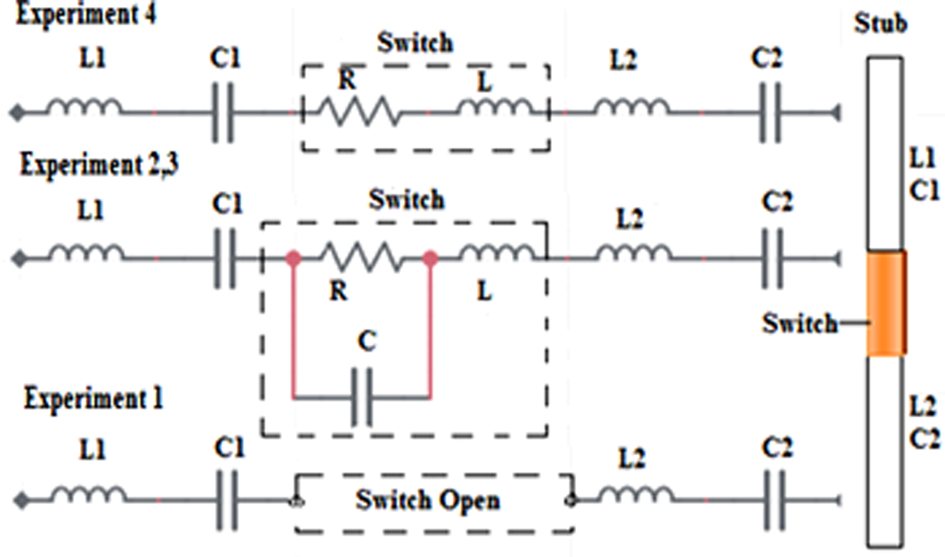
4 × 1.2 mm length and 0.85 mm thickness photodiodes are selected as a switch for simulation. These switches are activated by a light signal with or without DC bias voltage. The switch is connected serially between the two resonant circuits C1, L1 (upper part of the stub) and C2, L2 (lower part of the stub) as shown in Fig. 5. Experiment-1 is simulated without DC bias and light, Experiment-2, 3 are simulated through the lumped element assignment of photodiodes with the values R = 20 kΩ, C = 1.8 pf, L = 1 nH and R = 40 kΩ, C = 1.8 pf, L = 1 nH. Experiment-4 is simulated by assigning the values R = 50 Ω and L = 1 nH for the photodiodes. The effective length of the stubs can be adjusted by the internal resistance and capacitance variations of the switch.

Equivalent circuit of the switch.

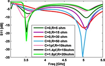
Figure 6 shows the antenna radiation frequencies at different resistance and capacitance values. At R = 50 Ω and L = 1 nH the antenna is radiating at 5 GHz and the values of R = 20 k, C = 1.8 pf the antenna is radiating at 3.5 and 5 GHz. But minimum return loss is achieved only at 5 GHz range at −0.5 to −1 DC biasing. This parametric analysis is done with the internal inductance value of 1nH and the blocking capacitance value of 2pf. The simulation results show the return loss value of −35 dB at 5 GHz.
R and C values of the Optical Switch.

Current distribution in antenna geometry
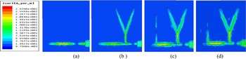
Figure 7 shows the current density flow of the antenna geometry. The values are given in blue color indicate low current density and upper values indicate high current density. When the feeding stub is only connected to the antenna their maximum field distribution is toward the end of the feeding stub. The V-shaped radiator is also connected to the feeding stub the electric field is moving toward the legs of the radiator. When the two tuning stubs are connected to the V-shaped radiator through the feeding stub, the field is moving toward the top of the tuning stubs. We can see that the involvement of tuning stubs and effective length of the tuning stubs with their current density flow in Figs 7(c) and 7(d).
Surface current distribution with (a) a feeding stub (b) Y-shaped radiator (c) Single stub (d) Double stub.

Results and discussion
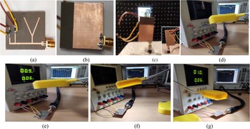
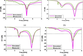
The antenna prototype is fabricated on Roger substrate with the dielectric constant of εr = 3.3 and the substrate thickness of 1.52 mm as shown in Figs 8(a) and 8(b). Roger substrate is a good choice for fabricating microstrip antennas because it reduces the dielectric loss and increases the gain at high frequencies over Fr-4 substrate. Two 4 mm length and 1.2 mm width TEMD7100IT SMD silicon PIN photodiodes are connected on the stub for switching purposes. The thickness of the switch is 0.85 mm and the radiant sensitive area is 0.23 mm2. A 5 watts LED table lamp is used along with an Anritsu MS2037C vector analyzer for measuring the antenna S 11 parameter and pattern measurement as illustrated in Fig. 8. Four different experiments are conducted for measuring the S 11 parameter of the proposed antenna as shown in Figs 8(d)–8(g). The reverse bias value selected for this antenna measurement is −1V. In Experiment-1, the antenna simulation result shows the radiation at 4.3 GHz and the measurement result shows the radiation at 4.32 GHz. The simulated and measured return losses are −35.4dB and −21 dB respectively. The photodiode switch performance is varied under light with biasing voltage and without DC bias voltage. When DC bias voltage of −0.9 to −1 V is applied to the switches without light(Experiment-2) the photodiode acts as a poor conductor because the value of junction resistance and capacitance increases and when the optical signal is applied to the photodiodes without DC bias voltage(Experiment-3) the antenna shifts the radiations at 3.5GHz and 5GHz.The antenna exhibits the radiation at 5 GHz with a return loss value of −20 dB with light and −1V DC bias (Experiment- 4). The simulated and measured return loss values at all experimental conditions are given in Fig. 9 and Table 2.
Fabricated antenna (a) Top view (b) Bottom View (c)Antenna pattern measurement at the anechoic chamber (d) Experiment-1(No DC bias and light) (e) Experiment-2(DC bias without light) (f) Experiment- 3 (Light present without DC bias) (g) Experiment-4 (light with DC bias).

Simulated and measured antenna S 11 parameters at (a) Exp.-1 (b) Exp.-2 (c)Exp.-3 (d) Exp.-4.

Simulation and measurement results comparison of the proposed antenna.

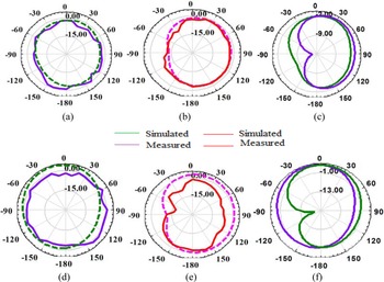
Figure 10 gives the normalized gain of the antenna at different frequencies (4.3GHz, 3.5GHz, and 5 GHz) under simulation and measured conditions. For the radiation pattern and gain measurement, a standard 12 dB gain horn antenna is used with a 2 m distance from the test antenna. The below comparisons show the accepted normalized gain between the simulation and experiments at φ = 0o and φ = 90o. The measured pattern is slightly changed in Experiment −2 and 3 due to losses created from PIN photodiodes, feeder and substrate. These losses are not considered in simulation so the measured gain values are normally lesser than the simulated values.
Radiation pattern of θ E at(X-Z plane) (a) φ = 0° at 4.3 GHz (d) φ = 90° at 4.3 GHz (b) φ = 0° at 3.5 GHz (e) φ = 90° at 3.5 GHz (c) φ = 0° at 5 GHz (f) φ = 90° at 5 GHz.

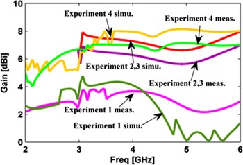
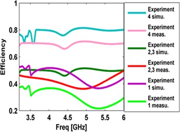
Figures 11 and 12 shows the efficiency and gain of the antenna. The proposed antenna exhibits maximum gain and efficiency in Experiment-4 and minimum gain and efficiency in Experiment-1. The antenna return loss, gain and efficiency comparisons are given in Table 2.
Gain of the antenna.

Efficiency of the antenna.

Conclusion
In this paper, a 47.6% compactness (44 × 28) mm optically controlled frequency reconfigurable antenna prototype is fabricated and their S 11, radiation pattern, gain and efficiency parameters are measured experimentally. The fabricated antenna produces frequency reconfiguration from 4.3 to 3.5GHz and 5 GHz with accepted return loss in both measurement and simulation. The designed antenna is a good candidate for future optically controlled IoT devices and wireless applications. The antenna can be used for radio altimeter at 4.3 GHz, WLAN at 5 GHz and 5G applications at 3.5 GHz. The antenna gives a maximum measured gain of 7.2 dBi and 10.2% bandwidth at 5 GHz.
Acknowledgement
This research work was funded by “Visvesvaraya Ph.D Scheme for Electronics & IT” Ministry of Electronics and Information Technology, the Government of India (unique awardees no MEITY-Ph.D-3061).
 V. Reji received the bachelor of engineering degree in electronics and communication engineering from Manonmanium Sundaranar University, Tamilnadu, India, in 2003. She received the master of engineering degree in communication systems from SRM University, India in 2011. Currently, She is doing her research in SRM Institute of Science and Technology, Chennai, India under “Visvesvaraya Ph.D Scheme for Electronics & IT” Ministry of Electronics and Information Technology, India.
 Dr. C. T. Manimegalai is currently working as an associate professor in the Department of ECE, SRM Institute of Science and Technology, Chennai, India. She has done her Ph.D in wireless communication in the year 2014. Her area of specialization includes wireless communication, antenna design and optical communication. She has received various funds from the government of India and filed patents. She is a member of several professional societies and a reviewer of reputed journals. She has published several papers in refereed journals.