



1 Introduction
The dynamics of a droplet or bubble pushed by a carrier fluid flowing in a confined space is a classical multiphase problem that has a long history. In such cases, a capillary interface develops between the immiscible droplet/bubble and the carrier fluid that wets the wall. A thin film is formed between the interface and the wall, lubricating the droplet/bubble. Despite knowledge of the fundamental picture of the thickness of the film, the shape of the menisci or the velocity of the suspended phase, and regardless of the steadfast efforts initiated in the 1960s by Bretherton (Reference Bretherton1961) and Taylor (Reference Taylor1961), investigating a bubble confined in a tube as the first step, the dynamics of translating droplets/bubbles under confinement is not yet well understood.
(a) A pancake droplet translating at velocity
 $U_{d}$
in a Hele-Shaw cell with gap width
 $H$
, driven by an ambient fluid with a mean velocity of
 $U^{\infty }$
. The film thickness is
 $h(x,y)$
as denoted in the inset. (b) A discretized drop with
 $Ca^{\infty }=0.02$
under confinement
 $R/H=2$
. Blue lines denote the walls and the green dashed curve indicates the nearly flat region of the film.

The existing literature focuses mainly on a moving droplet/bubble confined in a capillary tube or between two closely spaced parallel plates (Hele-Shaw cell). In the former case, Taylor (Reference Taylor1961) performed experiments by blowing air into a tube filled with a viscous liquid where the air forms a round-ended cylindrical bubble. He measured the bubble velocity
 $U_{d}$
compared with the mean velocity
 $U^{\infty }$
of the underlying flow, showing its excess velocity
 $m=(U_{d}-U_{\infty })/U_{d}$
as a function of the capillary number
 $Ca_{d}={\it\mu}U_{d}/{\it\gamma}$
, where
 ${\it\mu}$
denotes the dynamic viscosity of the liquid and
 ${\it\gamma}$
the surface tension; he also predicted the presence of stagnation points in the flow ahead of the front meniscus and how the number and location of the stagnations vary with
 $m$
. Almost at the same time, Bretherton (Reference Bretherton1961) conducted similar experiments and performed an axisymmetric lubrication analysis, showing that the lubrication equations were similar to their two-dimensional (
 $2$
D) version assuming spanwise invariance. He focused on the shape of the front/rear menisci, the pressure drop, the thickness of the lubrication film and the excess velocity
 $m$
. Bretherton established the well-known
 $2/3$
scaling between the non-dimensional film thickness
 $2h/H$
and the capillary number
 $Ca_{d}$
, namely,
 $2h/H=P(3Ca_{d})^{2/3}$
with
 $P=0.643$
, where
 $h$
and
 $H$
denotes the film thickness and the tube diameter respectively. The pre-factor
 $P$
could vary with the droplet/bubble’s interfacial rigidity (Bretherton Reference Bretherton1961; Cantat Reference Cantat2013), and the viscosity ratio between the droplet/bubble phase and the carrier phase (Teletzke, Davis & Scriven Reference Teletzke, Davis and Scriven1988).
The situation is more complicated in a Hele-Shaw cell where the droplet is so squeezed that it adopts a flattened pancake-like shape, leaving a lubrication film between its interface and the wet plates (figure 1). Such flattened droplets are encountered in the context of droplet-based microfluidics (Baroud, Gallaire & Dangla Reference Baroud, Gallaire and Dangla2010) where droplets are manipulated in microfluidic chips to achieve micro-reaction, therapeutic agent delivery and biomolecule synthesis, etc. (Teh et al. Reference Teh, Lin, Hung and Lee2008). Those chips are often thinner in the wall-normal direction than in others, in order to process simultaneously a large number of droplets constrained to move only horizontally. The problem of a moving pancake droplet in a Hele-Shaw cell hence serves as a model configuration to investigate the dynamics of those microfluidic droplets. Besides, the problem belongs to a larger set of research topics of moving menisci on a wet solid, a phenomenon that is involved in a broad range of industrial and natural situations (Cantat Reference Cantat2013) and has motivated pioneering studies (Park & Homsy Reference Park and Homsy1984; Meiburg Reference Meiburg1989; Burgess & Foster Reference Burgess and Foster1990) of the pancake droplet/bubble in a Hele-Shaw cell, as detailed below.
The dynamics of the Hele-Shaw droplet/bubble occur at different length scales spanning a broad range; their close coupling makes the problem truly multi-scale. The length scale in the unconfined direction is much larger than that in the confined direction. The latter corresponding to the gap width of the cell is again much larger than the thickness of the lubrication film. Thanks to the mathematical analogy between the governing equations of the depth-averaged Hele-Shaw flow and those of the
 $2$
D irrotational flow as proved by Stokes (Reference Stokes1898) and commented by Lamb (Reference Lamb1932), potential flow theory was adopted to study the motion of a Hele-Shaw bubble theoretically (Taylor & Saffman Reference Taylor and Saffman1959) and numerically (Tanveer Reference Tanveer1986). Park & Homsy (Reference Park and Homsy1984) formulated a rigorous theory of a two-phase displacement problem (a less viscous fluid displacing a viscous one in a Hele-Shaw cell) as a double asymptotic expansion in small capillary numbers,
 $Ca$
, and non-dimensional gap widths,
 ${\it\epsilon}$
, of the cell (scaled by its transverse characteristic length scale); the theory holds as long as the viscosity ratio
 ${\it\lambda}$
between the displacing and displaced fluid satisfies
 ${\it\lambda}=o(Ca^{-1/3})$
. Burgess & Foster (Reference Burgess and Foster1990) performed a multi-region asymptotic analysis for a Hele-Shaw bubble based on the same assumption of small
 $Ca$
and
 ${\it\epsilon}$
, focusing on the scaling dependence of the minimum/mean film thickness on
 $Ca$
and
 ${\it\epsilon}$
. Based on the stress jump derived by Bretherton (Reference Bretherton1961) and Park & Homsy (Reference Park and Homsy1984) that enables using lumped interfacial boundary conditions, depth-averaged
 $2$
D simulations were carried out by Meiburg (Reference Meiburg1989) for a Hele-Shaw bubble, including the leading-order effects of the dynamic meniscus hindering the movement of the bubble. In a similar vein, an alternative depth-averaged framework has been recently implemented by Nagel & Gallaire (Reference Nagel and Gallaire2015) by solving the so-called
 $2$
D Brinkman equations that take account of the in-plane velocity gradients.
These results are supposed to hold for a particular range of the parameter space due to their asymptotic nature and they have not been verified by either experiments or fully resolved three-dimensional (
 $3$
D) simulations. Moreover, these studies often neglected the viscosity of the droplet phase or considered very low viscosities. The asymptotic analysis also fails to provide information such as the interior/exterior flow field, a full
 $3$
D description of the droplet profile or lubrication film, or detailed connections with the droplet velocity. A tip of the iceberg has been revealed, and much effort will be required to reach a thorough understanding of the problem. Very recently, elaborate experiments have been performed by Huerre et al. (Reference Huerre, Theodoly, Leshansky, Valignat, Cantat and Jullien2015) to measure the thickness and topology of the lubrication film between a viscous, surfactant-laden droplet and the wall. They identified a regime where the interface resembles a catamaran shape featuring two protrusions formed on its lateral sides, without providing a detailed explanation about its physical origin. Very few
 $3$
D simulations have been conducted for a pancake droplet/bubble despite the very recent work of Ling et al. (Reference Ling, Fullana, Popinet and Josserand2016) for a droplet with small but finite inertia. Here, we simulate a matching-viscosity droplet (the fluid inside and outside has the same viscosity) in the inertialess regime based on an accelerated boundary integral method (BIM). We focus on the effect of the capillary number and the confinement (in other words the aspect ratio) of the droplet. We show the topology of the lubrication film and the spatial distribution of the film thickness. The dependence of the mean and minimum film thickness on the capillary number are reported, and they are compared with the numerical and theoretical predictions of a
 $2$
D droplet in a channel. Finally, we depict the flow field inside and outside the droplet, demonstrating its complex three-dimensionality.
2 Problem description
As shown in figure 1(a), we consider, in the creeping flow regime, a translating pancake droplet at velocity
 $U_{d}$
driven by an ambient flow inside two infinitely large plates placed at
 $z=\pm H/2$
. The fluids of the droplet phase and carrier phase are Newtonian, sharing the same dynamic viscosity
 ${\it\mu}$
; the viscosity ratio
 ${\it\lambda}$
between the two (droplet phase versus carrier phase) is
 $1$
. We solve the steady Stokes equations with no-slip boundary conditions on the plates and stress jump condition
 ${\bf\sigma}_{1}\boldsymbol{\cdot }\boldsymbol{n}-{\bf\sigma}_{2}\boldsymbol{\cdot }\boldsymbol{n}={\it\gamma}\boldsymbol{n}(\boldsymbol{{\rm\nabla}}_{S}\boldsymbol{\cdot }\boldsymbol{n})$
on the droplet interface, where
 ${\bf\sigma}_{1}$
and
 ${\bf\sigma}_{2}$
are the total stress tensors corresponding to the carrier phase and drop phase respectively,
 $\boldsymbol{n}$
is the unit normal vector on the interface pointing towards the carrier phase and
 $\boldsymbol{{\rm\nabla}}_{S}=(\boldsymbol{I}-\boldsymbol{n}\boldsymbol{n})\boldsymbol{\cdot }\boldsymbol{{\rm\nabla}}$
is the surface gradient. A Poiseuille flow with a mean velocity of
 $U^{\infty }$
is applied in the inlet, hence the ambient velocity field in is
 $\boldsymbol{u}^{\infty }=U^{\infty }(1.5-6z^{2}/H^{2},0,0)_{xyz}$
. The radius of the droplet at rest is
 $a$
and all the length scales hereinafter are scaled by
 $a$
unless otherwise specified. Since the thickness
 $h(x,y)$
of the lubrication film is much smaller than the gap width
 $H$
, the drop can be viewed as a cylinder of radius
 $R$
and height
 $H$
, where
 $R^{2}H=4a^{3}/3$
. We use
 $R/H$
to quantify the confinement. The surface tension of the droplet interface is
 ${\it\gamma}$
. We define capillary numbers based on the velocity of the underlying flow or that of the droplet, leading to
 $Ca^{\infty }={\it\mu}U^{\infty }/{\it\gamma}$
or
 $Ca_{d}={\it\mu}U_{d}/{\it\gamma}$
respectively.
3 Numerical methods
We use a BIM accelerated by the general geometry Ewald method (GGEM) proposed by Hernández-Ortiz, de Pablo & Graham (Reference Hernández-Ortiz, de Pablo and Graham2007) and Pranay et al. (Reference Pranay, Anekal, Hernandez-Ortiz and Graham2010). On top of a GGEM-based BIM code originally developed to simulate elastic capsules in general geometries (Zhu et al.
Reference Zhu, Rorai, Dhrubaditya and Brandt2014; Zhu & Brandt Reference Zhu and Brandt2015), we implement a new module to simulate droplets. Thanks to the linearity of Stokes equations, GGEM decomposes the flow field into two parts, a short-ranged, fast-decaying part solved by traditional BIM techniques, and a long-ranged, smoothly varying part handled by a Eulerian mesh-based solver for which we choose the spectral element method solver NEK5000 (Fischer, Lottes & Kerkemeier Reference Fischer, Lottes and Kerkemeier2008) here. For the details of our GGEM implementation, the reader is referred to Zhu & Brandt (Reference Zhu and Brandt2015). Our current work only accounts for a matching-viscosity droplet without the necessity for performing double-layer integrations, enabling us to follow directly the GGEM initially developed for the fast computation of the Stokes flow driven by a set of point forces. To simulate a non-matching-viscosity droplet (
 ${\it\lambda}\neq 1$
), we can further adopt the GGEM-accelerating BIM formulation (Kumar & Graham Reference Kumar and Graham2012) where the velocity field is expressed by a single-layer integration solely even for problems with non-matching viscosities.
In the original GGEM-based BIM code for capsules, the interface is discretized by spherical harmonics. For the droplet interface, we use triangular elements instead for the discretization (see figure 1 b). For a highly deforming interface that is far from a sphere, as in our case, the triangular elements would capture the geometrical details more accurately and flexibly compared to the spherical harmonics. Another benefit of this choice is that adaptive mesh refinement on the interface like that performed in Zhu, Lauga & Brandt (Reference Zhu, Lauga and Brandt2013) can be readily incorporated to more efficiently and robustly describe the fine-scale geometrical features.
Based on the triangular elements, we perform singular integration on the droplet interface using the plane polar coordinates with Gauss–Legendre quadrature, and a high-order near-singularity subtraction has also been adopted following Zinchenko & Davis (Reference Zinchenko and Davis2006). A robust fourth-order local fitting algorithm (see appendix B of Zinchenko & Davis (Reference Zinchenko and Davis2006) for details) is used to accurately calculate the surface normal vectors and curvatures of the interface. The most important feature incorporated is the so-called passive mesh stabilization scheme (Zinchenko & Davis Reference Zinchenko and Davis2013) which has dramatically improved the robustness of our simulations because the orthogonality and smoothness of the triangular elements are well guaranteed over a long time evolution. For validation, we simulated a droplet tightly squeezed in a long tube and observed excellent agreement with the data of Lac & Sherwood (Reference Lac and Sherwood2009) based on a
 $3$
D axisymmetric BIM implementation.
We used an open-source multiphase flow solver, Gerris (Popinet Reference Popinet2009), for some complementary simulations of a
 $2$
D drop in a channel. Rigorous validations against our own
 $2$
D BIM codes have been conducted. Gerris is adopted here to obtain accurate flow fields conveniently.
4 Results
We focus on the regime
 $Ca^{\infty }\in (0.007,0.16)$
when the capillary forces are important. Lower capillary numbers are not pursued because they would require prohibitively high computational cost due to the rapid decrease of the film thickness
 $h$
with decreasing
 $Ca^{\infty }$
. More precisely, numerical difficulties arise because of the singular perturbative nature of the problem at small
 $Ca^{\infty }$
values (Park & Homsy Reference Park and Homsy1984). Three confinement levels
 $R/H=1.5$
,
 $2$
and
 $3$
have been examined; their corresponding gap widths are
 $H=0.840$
,
 $0.693$
and
 $0.529$
. As depicted in figure 1, we denote the
 $x$
,
 $y$
and
 $z$
directions as the streamwise, spanwise and wall-normal directions, and the
 $yz$
,
 $xz$
and
 $xy$
planes as the transverse, vertical and horizontal planes.
4.1 Droplet velocity
Figure 2(a) depicts the dependence of the scaled droplet velocity
 $U_{d}/U^{\infty }$
with the capillary number
 $Ca^{\infty }$
and confinement
 $R/H$
. The velocity increases slightly with
 $R/H$
. This weak dependence is in accordance with the experimental observations of Shen et al. (Reference Shen, Leman, Reyssat and Tabeling2014) for
 ${\it\lambda}\approx 1.4$
and capillary numbers several orders smaller than ours. The scaled droplet velocity increases with
 $Ca^{\infty }$
monotonically and surpasses
 $1$
, in contrast with the predicted velocity of
 $U_{d}/U^{\infty }=1$
by Gallaire et al. (Reference Gallaire, Meliga, Laure and Baroud2014) for a matching-viscosity pancake droplet modelled by an undeformed cylinder at sufficiently low
 $Ca^{\infty }$
. The mismatch results from two drawbacks of their model: it neglects the impeding effect of the dynamics of the menisci of the drop at low
 $Ca^{\infty }$
; and it does not capture the film thickening at high
 $Ca^{\infty }$
that enhances the droplet velocity.
(a) The scaled droplet velocity
 $U_{d}/U^{\infty }$
as a function of
 $Ca^{\infty }$
for varying confinement. (b) Stretching the thin-film region of the drop as in figure 1(b) by
 $7.5$
times in
 $z$
.

Contour lines of the scaled film thickness
 $h/H$
for droplets with
 $Ca^{\infty }=0.007$
(a),
 $0.02$
(b) and
 $0.08$
(c) under confinement
 $R/H=2$
. The black contour line
 $h/H=0.5$
indicates the edge of the droplet cut by the
 $z=0$
plane.

4.2 Shape of the droplet and film thickness
To better visualize the fine-scale geometrical features of the drop shown in figure 1(b), we stretch its top interface by
 $7.5$
times vertically and the zoomed view is shown in figure 2(b). The interface clearly bulges on the rear half of the rim of the interface, displaying an arc-shaped ridge.
We show in figure 3 the contour lines of constant film thickness
 $h(x,y)/H$
for droplets with
 $Ca^{\infty }=0.007$
,
 $0.02$
and
 $0.08$
under confinement
 $R/H=2$
. Note that the height
 $z(x,y)$
of the droplet interface is inversely correlated to the film thickness
 $h(x,y)$
, i.e.
 $z(x,y)+h(x,y)=H/2$
. The black curve
 $h/H=0.5$
represents the edge of the droplet cut by the
 $z=0$
plane, which resembles a circle at
 $Ca^{\infty }=0.007$
but becomes elongated at
 $Ca^{\infty }=0.08$
. For all
 $Ca^{\infty }$
investigated, the contour map exhibits three local minima: one at the rear and a symmetric pair on the lateral edges. These minima correspond to the peaks of the interfacial protrusions. The two symmetric lateral protrusions are higher than the rear one. They have been recently observed experimentally for a pancake droplet with
 ${\it\lambda}=25$
by Huerre et al. (Reference Huerre, Theodoly, Leshansky, Valignat, Cantat and Jullien2015), who noted the resulting ‘catamaran-like shape’ adopted by the droplet. This feature has also been portrayed theoretically by Burgess & Foster (Reference Burgess and Foster1990), performing a multi-region asymptotic analysis of a pancake bubble (see figure 5 of their paper). As far as we know, our study represents the first computational work that identifies this unique interfacial topology.
Burgess & Foster (Reference Burgess and Foster1990) showed in the low capillary number limit that the contour lines of
 $h/H$
are streamwise parallel in the central film region (excluding the lateral portion) where the viscous forces dominate, resulting in flat film. The contour lines of the
 $Ca^{\infty }=0.08$
case are indeed parallel in the region
 $x\in (-1,1),y\in (-0.75,0.75)$
. At a reduced capillary number
 $Ca^{\infty }=0.007$
, such parallel lines disappear and the three protrusions instead occupy a large portion of the film, pointing to its
 $3$
D nature.
The scaled mean
 $\bar{h}/H$
(a) and minimum
 $h_{min}/H$
(b) film thickness versus the capillary number
 $Ca_{d}$
, for a pancake droplet under confinement
 $R/H=1.5$
(circles),
 $2$
(squares) and
 $3$
(diamonds). Its minimum thickness on the middle vertical slice is denoted by
 $h_{min}^{y=0}$
. The dashed curve corresponds the constant film thickness
 $h^{EB}/H$
of a
 $2$
D drop predicted by the EB model (Klaseboer, Gupta & Manica Reference Klaseboer, Gupta and Manica2014) with
 $P=0.6$
and
 $Q=1.5$
. The triangles denote the numerical data
 $h^{sim}|_{2D}/H$
(constant) and
 $h_{min}^{sim}|_{2D}/H$
(minimum) for a
 $2$
D drop.

We show in figure 4(a) the dependence of the mean thickness
 $\bar{h}$
on the capillary number.
 $Ca_{d}$
is adopted instead of
 $Ca^{\infty }$
to be consistent with prior studies. We obtain
 $\bar{h}$
by averaging
 $h$
over a central circular patch with radius
 $R_{cen}=0.3R_{xy}$
, where
 $R_{xy}$
is the effective radius of the nearly circular droplet profile in the
 $z=0$
plane. The scaled film thickness
 $\bar{h}/H$
increases with
 $Ca_{d}$
monotonically and weakly depends on
 $R/H$
.
For comparison, we use the flow solver Gerris to simulate a
 $2$
D matching-viscosity droplet in a channel of width
 $H$
where the droplet length is much larger than its size in the confined direction. The film far away from the dynamic menisci is almost flat with a constant thickness of
 $h^{sim}|_{2D}$
which is reported in figure 4(a). Additionally, we include the prediction of the extended Bretherton (EB) model proposed by Klaseboer et al. (Reference Klaseboer, Gupta and Manica2014) for a bubble, according to which, apart from the dynamic meniscus regions, the lubrication film has a constant thickness of
 $h^{EB}$
 $$\begin{eqnarray}\displaystyle h^{EB}/H=\frac{1}{2}\frac{P(3Ca_{d})^{2/3}}{1+PQ(3Ca_{d})^{2/3}}, & & \displaystyle\end{eqnarray}$$
where
 $H$
is the tube diameter, and
 $P=0.643$
and
 $Q=2.79$
(Bretherton Reference Bretherton1961). This model agrees well with the empirical fit of Aussillous & Quéré (Reference Aussillous and Quéré2000) of Taylor’s (Reference Taylor1961) experimental data. We adopt
 $P=0.6$
and
 $Q=1.5$
in (4.1), and the fitted thickness
 $h^{EB}/H$
almost coincides with the numerical value
 $h^{sim}|_{2D}/H$
. The mean film thickness
 $\bar{h}/H$
agrees well with the two values
 $h^{sim}|_{2D}/H$
and
 $h^{EB}/H$
of the
 $2$
D drop at low capillary numbers, but starts deviating when
 $Ca_{d}$
increases. As the confinement increases, the film thickness
 $\bar{h}/H$
agrees better with the
 $2$
D results. The agreement between
 $\bar{h}/H$
with the thickness
 $h^{sim}|_{2D}/H\approx h^{EB}/H$
can be attributed to two reasons: first, the central region where
 $\bar{h}$
is measured is rather flat, as illustrated by the sparsely distributed contour lines in figure 3, implying the mean film thickness
 $\bar{h}$
adopts the constant thickness
 $h$
of the vertical slice (
 $y=0$
); second, as we will show in § 4.3, the velocity field of this slice strongly resembles that of a
 $2$
D matching-viscosity droplet.
Velocity field in the droplet frame including the vectors and streamlines of the flow (a) on the
 $y=0$
plane of the drop with
 $Ca^{\infty }=0.007$
and
 $R/H=2$
, (b) of a
 $2$
D droplet with
 $Ca^{\infty }=0.007$
and
 ${\it\lambda}=1$
travelling in an infinitely long channel. Red curves denote the droplet interface and black/magenta/tip circles denote the interfacial/axial/tip stagnation points; the contour colour indicates the in-plane velocity magnitude scaled by the droplet velocity
 $|\mathbf{u}|/U_{d}$
.

We plot in figure 4(b) the scaled minimum film thickness
 $h_{min}/H$
of the pancake droplet, where
 $h_{min}^{y=0}/H$
denotes the scaled minimum thickness of its middle vertical slice, and
 $h_{min}^{sim}|_{2D}/H$
that of the
 $2$
D drop. For all
 $R/H$
,
 $h_{min}^{y=0}/H$
is slightly below
 $h_{min}^{sim}|_{2D}/H$
and increases with
 $R/H$
. For the most confined case,
 $R/H=3$
,
 $h_{min}^{y=0}/H$
agrees with
 $h_{min}^{sim}|_{2D}/H$
reasonably well, which is in accordance with the agreement between their mean thickness counterparts, i.e.
 $\bar{h}/H$
and
 $h^{sim}|_{2D}/H$
, as discussed previously.
The global minimum
 $h_{min}/H$
is, however, approximately half of the local
 $h_{min}^{y=0}/H$
, as can be inferred from the minima of the contour maps (figure 3) that represent the thickness of the film above the lateral and rear interfacial protrusions. The difference between these two minima indicates the
 $3$
D nature of the droplet interface. Note that, while
 $\bar{h}/H$
slightly increases with the confinement
 $R/H$
,
 $h_{min}/H$
decreases significantly with
 $R/H$
, especially at large
 $Ca_{d}$
numbers. This suggests that the
 $3$
D nature is more pronounced for a more confined drop.
4.3 Flow field in the reference frame of the droplet
In this section, we focus on the flow field,
 $\boldsymbol{u}_{drop}=\boldsymbol{u}_{lab}-(U_{d},0,0)_{xyz}$
, in the reference frame of the droplet, where
 $\boldsymbol{u}_{lab}$
indicates that in the lab frame; the disturbance flow field will be discussed in § 4.4. The velocity fields projected on the vertical, horizontal and transverse planes in the reference frame of the drop are depicted. We first show in figure 5(a) that on the middle vertical plane
 $y=0$
of the drop with
 $Ca=0.007$
under confinement
 $R/H=2$
. We compare it to the
 $2$
D drop with
 ${\it\lambda}=1$
in figure 5(b). We find the two flow patterns resemble each other closely, supporting the hypothesis made in § 4.2 regarding their film thickness. In the top-half domain, the interior flow consists of three recirculating zones, two clockwise ones appearing beside the front and rear meniscus respectively and a third anti-clockwise one in between; they are clearly distinguished by six stagnation points, two on the interface (black circles), two on the axis (magenta circles) and the other two as the tips (green circles) of the droplet. The front interfacial stagnation point has been predicted for an axisymmetric inviscid bubble in a tube by Taylor (Reference Taylor1961), as also discussed by Hodges, Jensen & Rallison (Reference Hodges, Jensen and Rallison2004). The recirculation has been observed numerically by Westborg & Hassager (Reference Westborg and Hassager1989) and Martinez & Udell (Reference Martinez and Udell1990) for an axisymmetric viscous droplet both near its front and rear meniscus, as well as by Ling et al. (Reference Ling, Fullana, Popinet and Josserand2016) for a
 $2$
D drop with
 ${\it\lambda}\approx 1.35$
.
As explained by Martinez & Udell (Reference Martinez and Udell1990), this flow structure appears as a result of the combination of the shear exerted by the wall onto the film and the zero net flux condition inside the drop. The interface tends to follow the moving wall to reduce the viscous dissipation in the film, producing the interior backward flow; the zero net flux condition dictates a compensating forward flow in the near-axis region. This global balance results from the local divergence-free condition
 $\partial u_{x}^{2D}/\partial x+\partial u_{z}^{2D}/\partial z=0$
.
This
 $2$
D scenario holds in any vertical slice of a spanwise, infinitely long droplet confined by two plates. But there is no reason why this condition should be satisfied in the middle slice of the ‘pancake’. The symmetry imposes indeed
 $u_{y}=0$
but not necessarily
 $\partial u_{y}/\partial y=0$
. The similarity between the two flows shows a posteriori that the in-plane divergence-free condition is approximately verified though,
 $\partial u_{x}/\partial x+\partial u_{z}/\partial z=-\partial u_{y}/\partial y\approx 0$
. This will be confirmed in the horizontal flow fields investigated next.
In figure 6, we display the velocity fields on the planes located at
 $z=0$
,
 $0.1$
,
 $0.2$
and
 $0.285$
together with the colour-coded wall-normal velocity
 $u_{z}$
; note that the walls are located at
 $z=\pm 0.347$
. The flow field can be partitioned into three patches depending on the radial position
 $r_{xy}$
with respect to the origin: first, the inner patch that is circular (
 $r_{xy}\lessapprox 1$
) inside which the flow is mostly in the streamwise direction, i.e.
 $u_{y}\approx 0$
and
 $\partial u_{y}/\partial y\approx 0$
; second, the outer patch (
 $r_{xy}\gtrapprox 1.5$
) that contains the flow passing around the droplet; and third, the annular patch (
 $1\lessapprox r_{xy}\lessapprox 1.5$
) that bridges the other two, where the flow mainly follows the in-plane curvature of the interface (red). The flow inside all the patches varies direction when the horizontal plane shifts from the middle
 $z=0$
towards the top wall. More specifically, in the inner patch, the flow goes forward at
 $z=0$
but backward at
 $z=0.285$
, reflecting the anti-clockwise recirculation on the vertical planes (see figure 5
a). In addition, the low in-plane velocities at
 $z=0.2$
correspond to the core of this recirculation. The velocity field in the outer patch represents the relative motion of the ambient flow with respect to the drop: near
 $z=0$
, the flow is faster than the drop and ‘pushes’ it; near the wall, the flow is slower and ‘retards’ it. The annular patch encompasses the droplet interface, and due to the non-penetration condition, the flow mostly follows the motion of the fluid elements along the interface: at
 $z=0$
, the ambient flow ‘pushes’ the droplet forward, resulting in a clockwise annular flow; near the top wall, the ambient flow ‘drags’ the droplet backward resulting in a counter-clockwise flow. Unlike the middle vertical slice, the in-plane divergence-free condition in the middle horizontal plane is clearly broken, as a source (respectively a sink) emerges on the axis at
 $x\approx -1.3$
(respectively
 $x\approx 1.2$
) which exactly corresponds to the back (respectively the front) axial stagnation point on the middle vertical plane (see figure 5
a).
Flow on the horizontal planes at (a)
 $z=0$
, (b)
 $z=0.1$
, (c)
 $z=0.2$
and (d)
 $z=0.285$
for the same drop as in figure 5(a), shown in half (
 $y\geqq 0$
) of the domain. The top wall is located at
 $z=0.347$
. The contour colour indicates the wall-normal velocity
 $u_{z}$
. A reference vector with norm
 $|\mathbf{u}|=1$
is given. Red curves represent the droplet interface cut by the planes and the black dashed curves indicate the radial position of
 $r_{xy}=1$
and
 $r_{xy}=1.5$
. Magenta circles in (a) denote the same axial stagnation points as in figure 5(a).

We then come to the flow in the transverse planes shown in figure 7. Because of symmetry, we focus on the quarter (
 $y\geqq 0,z\geqq 0$
) and we zoom in the lateral interface of the drop. We observe two vortical structures aligned in the streamwise direction: one at the rear, rotating clockwise, and the other in the front, rotating anti-clockwise. The two structures are most intense at approximately
 $x=-0.85$
and
 $0.85$
, i.e. where their axis intersects the interface; they both decay in strength away from these maximum swirl regions and are connected at a no-swirl position slightly aft the droplet centre, i.e. between the
 $x=-0.15$
and
 $x=0$
plane. At this position, the vorticity switches sign and streamlines change their spiralling direction. These streamwise vortex structures are closely related to the flow in the horizontal planes shown in figure 6: at
 $x=-0.85$
and
 $y\approx 1$
, the flow is in the positive (respectively negative)
 $y$
direction in the annular patch at
 $z=0$
(respectively
 $z=0.285$
), which generates a clockwise vortex; the vortex at
 $x=0.85$
appears likewise though oppositely oriented, because the flows in the annular patch reverse their spanwise directions.
Flow on the transverse planes at (a)
 $x=-0.85$
, (b)
 $x=-0.4$
, (c)
 $x=-0.15$
, (d)
 $x=0$
, (e)
 $x=0.4$
and (f)
 $x=0.85$
for the same drop as shown in figure 5(a), illustrated near the droplet interface (red) in the
 $y\geqq 0,z\geqq 0$
quarter of the domain. The contour colour indicates the streamwise velocity
 $u_{x}$
. A reference vector with norm
 $|\mathbf{u}|=0.4$
is given.

Disturbance flow field on the
 $y=0$
plane of the droplet analysed in § 4.3.

4.4 Disturbance flow field
We hereby analyse the disturbance flow
 $\boldsymbol{u}^{\prime }=\boldsymbol{u}_{lab}-\boldsymbol{u}^{\infty }$
induced by the presence of a translating pancake droplet, where
 $\boldsymbol{u}^{\infty }=U^{\infty }(1.5-6z^{2}/H^{2},0,0)_{xyz}$
. For the same drop as that examined in § 4.3, we depict
 $\boldsymbol{u}^{\prime }$
on the middle vertical plane in figure 8. In most of the domain, the disturbance flow is parallel, in the direction against the underlying flow. This represents the obstructive effect of the droplet travelling at a velocity
 $U_{d}$
smaller than the mean flow velocity
 $U^{\infty }$
; in other words, the extra pressure drop stemming from the presence of the droplet is positive. Interestingly, the disturbance flow
 $\boldsymbol{u}^{\prime }$
reverses its direction near the front and rear dynamic meniscus regions that extend from the lubrication film towards the static meniscus regions. As a result, two vortical structures aligned in the positive
 $y$
direction emerge, akin to those observed in the flow field in the droplet frame
 $\boldsymbol{u}_{drop}$
projected on the transverse (
 $yz$
) planes as shown in figure 7. In fact, the projections of
 $\boldsymbol{u}^{\prime }$
,
 $\boldsymbol{u}_{lab}$
and
 $\boldsymbol{u}_{drop}$
on the transverse planes are equivalent, because both the droplet velocity and the underlying flow
 $\boldsymbol{u}^{\infty }$
have only one non-zero component that is the
 $x$
component.
The disturbance flow field
 $\boldsymbol{u}^{\prime }$
projected on three horizontal planes is shown in figure 9. On the middle
 $z=0$
plane, the droplet sucks in/ejects fluid in the front/rear, the interior flow is mostly parallel and opposite to the moving direction of the droplet but reverses the sign near its lateral edge. This resembles a
 $2$
D dipolar flow field decaying as
 $1/r^{2}$
(see figure 9
e for a typical sketch), which has been observed experimentally for a pancake droplet by Beatus, Tlusty & Bar-Ziv (Reference Beatus, Tlusty and Bar-Ziv2006). This dipolar field, as an elementary solution of potential flow, was also assumed to predict the velocity of a buoyancy-driven bubble (Maxworthy Reference Maxworthy1986). In figure 9(d), we examine how the disturbance velocity magnitude
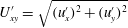 $U_{xy}^{\prime }=\sqrt{(u_{x}^{\prime })^{2}+(u_{y}^{\prime })^{2}}$
varies with the radial distance
 $r=\sqrt{x^{2}+y^{2}}$
, along the three paths emitting from the centre of the domain; the angles between these paths and the positive
 $x$
direction are
 ${\it\theta}={\rm\pi}/4,{\rm\pi}/2$
and
 $3{\rm\pi}/4$
. The log–log plot in the inset indicates that the decaying rate does indeed closely follow the
 $1/r^{2}$
scaling law. The dipolar flow field is also detected on the
 $z=0.15$
plane with a decreased strength. However, it disappears on the
 $z=0.285$
plane where the droplet ejects/sucks in fluid near its front/rear meniscus; this reversed disturbance flow has in fact been revealed on the middle vertical plane in figure 8.
Disturbance flow field
 $\boldsymbol{u}^{\prime }$
projected on the horizontal planes at (a)
 $z=0$
, (b)
 $z=0.15$
, (c)
 $z=0.285$
for the same drop as in figure 8(a); the contour colour indicates the disturbance velocity magnitude
 $U_{xy}^{\prime }/U_{d}$
. (d) Spatial variation of
 $U_{xy}^{\prime }/U_{d}$
on the
 $z=0$
plane, along three directions; the inset shows the log–log scale. (e) Sketch of a typical dipolar flow pattern.

5 Conclusions and discussions
We report a
 $3$
D computation of a translating pancake droplet in a Hele-Shaw cell. The cell gap width is around
 $0.5\sim 0.85$
the radius of a relaxed drop and the capillary number is in the range
 $[0.007,0.16]$
. In droplet-based microfluidic applications, the capillary numbers are smaller than our values by an order of one to two (Shen et al.
Reference Shen, Leman, Reyssat and Tabeling2014; Huerre et al.
Reference Huerre, Theodoly, Leshansky, Valignat, Cantat and Jullien2015) and the droplets are generally more confined. Still, we believe our computational study has taken a first step towards handling these realistic situations by extending the previously explored parameter space.
Our simulations together with the recent experiments by Huerre et al. (Reference Huerre, Theodoly, Leshansky, Valignat, Cantat and Jullien2015) and the prior asymptotic analysis by Burgess & Foster (Reference Burgess and Foster1990) confirm a common and unique interfacial topology of a pancake droplet/bubble, viz. a pair of protrusions formed symmetrically on the lateral rim of the rear-half interface. The viscosity ratios of the three studies are
 ${\it\lambda}=1$
,
 $25$
and
 $0$
respectively, suggesting that this topology is rather insensitive to the viscosity ratio. As a complementary clue, the work of Lhuissier et al. (Reference Lhuissier, Tagawa, Tran and Sun2013) is worth noting. They investigated experimentally and theoretically the levitation of an oil drop (
 ${\it\lambda}\approx 2500$
) on a moving wall mediated by the air film between them, observing a ridge of minimum film thickness on the downstream and lateral sides; although not explicitly mentioned, three closed iso-contour patterns were revealed, indicating the interfacial protrusions (see their video Saito, Tagawa & Lhuissier (Reference Saito, Tagawa and Lhuissier2014)).
The velocity field in the vertical planes closely resembles that of a
 $2$
D droplet in a channel, while an analogous resemblance is missing in the horizontal planes. For a
 $2$
D unconfined droplet or a
 $2$
D Brinkman model of the drop (Gallaire et al.
Reference Gallaire, Meliga, Laure and Baroud2014) where the confinement of Hele-Shaw cell is depth-averaged, the interior flow pattern in the drop frame, is featured with two symmetric counter-rotating recirculation regions to satisfy the zero net flux condition; the drop’s lateral interfaces recede due to the backward viscous forces from the exterior flow and consequently the flow near the symmetry axis advances to ensure global balance. For a
 $3$
D pancake droplet, this feature is, however, absent in the horizontal planes. Recirculation therefore takes place in a preferential direction, in the vertical planes in which the drop is confined but not in the horizontal unconfined planes. This preference results from the anisotropy of the wall confinement as the viscous forces on the droplet interface in the vertical planes overwhelm those active in the horizontal planes. Indeed, the lubrication film bridging the wall and the interface is so thin that the viscous effects in the former case play a dominant role in the determination of the flow pattern.
Despite the
 $3$
D feature of the flow, we have recovered that a moving pancake droplet induces a dipolar disturbance flow that can be described by a
 $2$
D velocity potential
 ${\it\phi}^{\prime }$
. The dipole and the potential characterizing the disturbance are
 $\boldsymbol{d}=(R^{2}(U_{d}-U^{\infty }),0)_{xy}$
and
 ${\it\phi}^{\prime }=-\boldsymbol{d}\boldsymbol{\cdot }\boldsymbol{r}/r^{2}$
respectively, where
 $\boldsymbol{r}$
is the position vector with respect to the droplet centre. This shows that the leading contribution of the disturbance flow,
 $\boldsymbol{{\rm\nabla}}{\it\phi}^{\prime }$
, decays as
 $1/r^{2}$
. This scaling is attributed to the confining effect of the two parallel walls and is important to bear in mind when considering the hydrodynamic interactions among several pancake droplets or among the droplets and the lateral boundaries in micro-fluidic chips.
Planned future work includes the analysis of force balance on the droplet, determining its velocity based on the obtained
 $3$
D data, as well as the extension of our GGEM-based BIM code to account for non-matching-viscosity droplets and interfacial transport of insoluble surfactants.
Acknowledgements
We thank Dr E. Lac for sharing the data of Lac & Sherwood (Reference Lac and Sherwood2009). Dr M. Nagel and G. Gallino are acknowledged for performing
 $2$
D BIM computations in support of validating our Gerris set-up. We thank G. Balestra for delightful discussions. This work was supported by a grant from the Swiss National Supercomputing Centre (CSCS) under project ID s603. The European Research Council is acknowledged for funding the work through a starting grant (ERC SimCoMiCs 280117).



