Introduction
Multiple-input multiple-output (MIMO) technology uses array configuration by employing several antennas at two ends of the communication link. It is well-known that using MIMO antennas are inevitable for attaining high-speed data transmission and higher reliability [Reference Chen, Liu and Nakano1]. On the other hand, improving the isolation characteristic of a MIMO system by consideration of device compactness is a significant challenge [Reference Ren, Zhao and Wu2]. Till now, numerous MIMO antennas with different designs that use several isolation methods to improve the antenna performance were presented in the literature [Reference Aw, Ashwath and Ali3–Reference Nasirzade, Nourinia, Ghobadi, Shokri and Naderali8]. In [Reference Aw, Ashwath and Ali3, Reference Azarm, Nourinia, Ghobadi and Majidzadeh4] two elements of the MIMO antennas are placed orthogonally to achieve isolation. In addition, to enhance the isolation, a parasitic structure embedded between elements in [Reference Azarm, Nourinia, Ghobadi and Majidzadeh4]. Furthermore, four-element MIMO antennas are presented in [Reference Ding, Gao, Qu and Yin5–Reference Nasirzade, Nourinia, Ghobadi, Shokri and Naderali8]. The antenna in [Reference Ding, Gao, Qu and Yin5] is comprised of a meander dipole, a reflector, and a parasitic strip. Four antenna elements in this design are located orthogonal to each other with a square loop configuration to reduce the size and improve the isolation. This antenna has an impedance bandwidth (IBW) of 23.9% (0.63, 2.32–2.95 GHz) while the isolations between the adjacent and opposite elements are <−14 and −18 dB with a total dimension of 85 × 85 mm2. Also, the envelope correlation coefficient (ECC) parameter between the adjacent and opposite elements is <0.008 and 0.003, respectively. Another design of a four-element MIMO system, including L-monopole antennas, is reported in [Reference Sarkar and Srivastava6]. The mentioned antenna has IBW of 58.6% (2.24, 2.70–4.94 GHz), minimum isolation of 11 dB and ECC <0.1 with a total size of 40 × 40 mm2. In addition, a four-element MIMO antenna with half-circle shape monopoles is presented in [Reference Hassan and Sharawi7], in which the antenna dimension is 110 × 60 mm2 and 230 MHz IBW with minimum 11 dB isolation between the elements is realized. Most recently, a new four-element MIMO antenna composed of four symmetrical dipoles with integrated baluns is presented [Reference Nasirzade, Nourinia, Ghobadi, Shokri and Naderali8]. The parallel elements with the same polarization isolated from each other by choosing a suitable distance and the isolation of adjacent elements with orthogonal polarization are guaranteed by polarization diversity in this work.
Many other designs use more ports the same as the proposed antenna in [Reference Zhao and Ren9], which presents an 8-element MIMO antenna.
Generally, MIMO antennas may have linear polarization (LP) or circular polarization (CP). However, typically the CP is preferred due to its advantages such as the ability to overcome multipath fading, admirable behavior in bad weather conditions, and acceptable mobility. Consequently, the CP produces a considerably high quality of communication service [Reference Mohammadi, Nourinia, Ghobadi, Pourahmadazar and Shokri10, Reference Shokri, Rafii, Karamzadeh, Amiri and Virdee11]. Nowadays, many researchers attempt to design CP antennas with various techniques and satisfactory radiation properties [Reference Shirzad, Shokri, Amiri, Asiaban and Virdee12–Reference Ellis, Ahmed, Kponyo, Effah, Nourinia, Ghobadi and Mohammadi14]. One of these techniques is using Tia Chi-shape in antenna's configuration [Reference Saygin, Rafiei and Karamzadeh15, Reference Karamzadeh, Saygin and Rafiei16]. In [Reference Saygin, Rafiei and Karamzadeh15] by using an asymmetric microstrip feed line and a parasitic patch, a complete Tai chi-shape in the antenna structure is realized and it achieves IBWs from 3.1 to 4.58 and 4.97–6.53 GHz and axial ratio bandwidths (ARBWs) from 3.26–4.42 and 5.45–6.63 GHz. In addition, a CP array antenna introduced in [Reference Karamzadeh, Saygin and Rafiei16] uses semi-fractal radiation patches with Tai chi-shape, which covers the frequency range from 5.3 to 6.8 GHz and has ARBW from 5.4 to 6.6 GHz. The Tai Chi-shape for other purposes in antenna design such as radar cross-section (RCS) reduction is also used [Reference Luo, Zhang and Zhuang17]. Furthermore, Tai Chi-shape element is used in [Reference Niu, Liang, Wu and Lin18] to realize a dual-band antenna covers two frequency bands from 2.4 to 2.49 GHz and from 5.07 to 5.88 GHz.
In this work, a new design of four-element MIMO antenna is presented which employed Tai Chi-shaped radiation elements and microstrip feed lines. The antenna achieves two resonant frequencies. The first one is at around 7.75 GHz and the second one with CP radiation is at approximately 10.15 GHz frequency. The measured isolations between ports with 46.7 × 46.7 mm2 total dimensions are <−20 dB. To realize the intended isolation, the adjacent feed lines are placed orthogonally to each other and decoupling crossed-slot and crossed-strip embedded to enhance the isolation. L-shaped feeds and appropriate rotation of surface currents on the Tai Chi-shaped patches generate the CP operation of the antenna. Because of the popular properties of printed patch antennas such as lightweight, acceptable radiation features and ease of fabrication, the proposed design is printed on FR4 substrates [Reference Shokri, Rafii, Karamzadeh, Amiri and Virdee19].
Antenna design
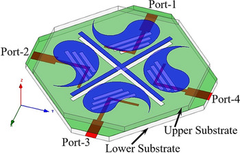
The geometry of the proposed four-element MIMO antenna is shown in Fig. 1. The antenna comprises three conducting layers separated by two similar octagonal-shaped FR4 substrates with a thickness of 1.6 mm, loss tangent of 0.02, and permittivity of 4.4. As seen in this figure, the lower substrate contains four L-shaped microstrip feed lines at the four shorter edges and a ground plane. In this design, the feed lines and ground plane are located at the down and up sides of the substrate, respectively, in a way that the ground plane is common for all ports. Furthermore, three rectangular-shaped slots with different sizes are etched under each patch on the ground plane to generate an aperture-coupled structure. These slots approximately cover the patch surface above the L-shaped feed. In addition, the upper substrate, that only included four Tai Chi-shaped patches on the top side, is put over the lower substrate and fixed there. Accordingly, the thickness of the MIMO antenna becomes 3.2 mm.
The geometry of the proposed four-element MIMO antenna.

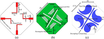
It is worthwhile to mention that for accessing the ground plane and soldering the SMA connectors to the antenna ports, the upper substrate is truncated at the shorter edges by 2 mm. Accordingly, a Tai Chi-shaped patch, a microstrip line with L-shaped feed, three slots, and one port altogether produce one of the antennas of the MIMO system. The conductor layers of the proposed antenna are illustrated in Fig. 2. As seen in Fig. 2(a) the width and length of the microstrip lines to meet the 50 Ω impedance matching are chosen 2.7 and 6 mm, respectively, and connected to the L-shaped feeds to excite two orthogonal resonant modes for CP radiation. Moreover, the ground plane entitled middle conductor layer is shown in Fig. 2(b). It consists of three rectangular-shaped slots with lengths of 12, 10, and 8 mm and the width of 1 mm for each port to realize the aperture-coupled structure. To cover the majority of the patch surface by the feed, three slots between the patch and L-shaped feed are used. Thus, it produces approximately strong coupling. Besides, the Tai Chi-shaped patches are placed over the upper substrate as seen in Fig. 2(c). Moreover, decoupling crossed-strip between patches and decoupling crossed-slot etched on the ground plane between the ports is used to improve the isolation as shown in Fig. 2. According to this figure, the Tai Chi shapes are generated simply by a circle with a radius of Rp and two circles with a radius of Rp/2. The radius of Rp is set to 8.45 mm and the distance between antenna elements is fixed at 25 mm. Other dimensions are reported in Fig. 2. The radiation patch, slots, and feed line for each port are individual except the ground plane and decoupling elements, which are common for all ports.
Proposed four-element MIMO antenna: (a) bottom conductor layer, (b) middle conductor layer, and (c) top conductor layer. (All dimensions are in millimeter).

Results and discussion
The S-parameters of the MIMO antenna at four ports are depicted in Fig. 3.
Simulated S-parameters of the MIMO antenna for all ports.

Due to the symmetrical structure, the proposed antenna has similar responses for the ports, which indicate that two IBWs centered around 7.8 GHz and 10 GHz with S 11 <−10 dB are achieved. According to the simulated results, the MIMO antenna has IBWs of 7.72–7.99 GHz and 9.39–10.27 GHz for port-1, 7.69–7.98 and 9.38–10.26 GHz for port-2, 7.65–7.95 and 9.37–10.30 GHz for port-3, and 7.72–8.09 and 9.40–10.32 GHz for port-4. In addition, the isolation graphs of the proposed antenna between the different ports are reported in Fig. 4.
Simulated isolations between the different ports of the MIMO antenna.

As seen in this figure, the isolations of more than 20 dB are realized for the proposed antenna. Two techniques are employed for improving the isolation in this work. First, the adjacent feeds are located orthogonally to each other and the second one, using decoupling structures between the radiating elements and similarly between the ground slots. Because of antenna compactness, we use a simple structure for decoupling. So a crossed-strip between patches and a crossed-slot on the ground plane between the ports is used to improve the isolation. In fact, the decoupling structures prevent the coupling currents from one port to another. The effect of the decoupling structures on the antenna isolations is illustrated in Fig. 5. Generally, the isolations can be separated into two categories in this design, isolation between the orthogonal ports and between the parallel ports.
The effect of the decoupling elements on the antenna isolations.

Therefore, in this case, the ports, which are located in face-to-face positions, named parallel ports and the adjacent ports that are perpendicular to each other are called orthogonal ports. The figure clarifies that the presence of decoupling elements between the antenna ports improves the isolation significantly. Furthermore, a very important parameter in MIMO systems, which explains the coupling level between any two antennas, is the ECC. It is an appropriate manner to display the diversity performance of a MIMO system. Subsequently, smaller values for the ECC guarantees using reasonable antenna diversity. The ECC parameter can be evaluated from the S-parameters using (1) [Reference Li, Zhang, Wang, Chen, Chen, Li and Zhang20]. In this formula, the S(ii) is the reflection coefficient of the antenna (i) and S(ij) (with i ≠ j), is the transmission coefficient between the antenna (i) and the antenna (j).

Figure 6 exhibits the ECC curves for the parallel and orthogonal ports of the proposed MIMO antenna system with a maximum value of 0.005. Also, the figure shows that the correlation coefficient between the orthogonal ports is a little bit more than the parallel ports and the ECC almost equal to zero around the resonant frequencies.
ECC curves for the parallel and orthogonal ports of the proposed MIMO antenna system.

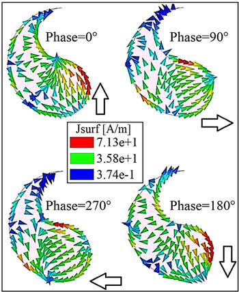
On the other side, orthogonal electric fields are generated due to the feed and radiation patch shapes, which leads to exciting CP radiation. Indeed the Tai chi shape of patch provides good conditions to have a clock wise (CW) rotation for surface currents and improves the AR response of the MIMO antenna.
Figure 7 shows the simulated AR curves for the MIMO antenna at four ports. The 3-dB ARBW extends between 9.73 and 10.46 GHz for port-1, 9.72–10.42 GHz for port-2, 9.70–10.38 for port-3, and 9.74–10.46 for port-4 as presented in Fig. 7.
Simulated AR curves for the MIMO antenna at port-1 to -4.

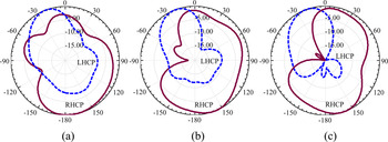
Moreover, the surface current distribution over the Tai Chi-shaped patch, at the frequency of lowest point of AR curve (10 GHz) is plotted in Fig. 8 whereas the port-1 is excited. As seen, it is clear that the surface currents with phases of 0°, 90°, 180°, and 270° have a CW rotation on the patch. In addition, the simulated gains for the proposed MIMO antenna with the optimized dimensions for four ports are shown in Fig. 9. The observed gains at all ports are almost equal and their variations are less than 2 dBic. The normalized right-hand CP (RHCP) and left-hand CP (LHCP) radiation patterns of the MIMO antenna at frequencies of 9.8, 10, and 10.2 GHz in the zy-plane (φ = 0°) are plotted in Fig. 10. All EM simulation results in this study have been carried out using high-frequency structure simulator (HFSS) Ver.13.
Current distributions on the Tai Chi-shaped patch at 10 GHz in 0°, 90°, 180°, and 270° phases.

Simulated gain curves for the MIMO antenna at port-1 to -4.

Simulated normalized RHCP and LHCP radiation patterns of the MIMO antenna at frequencies of (a) 9.8, (b) 10, and (c) 10.2 GHz in the zy-plane (port-1).

Fabrication and measurements
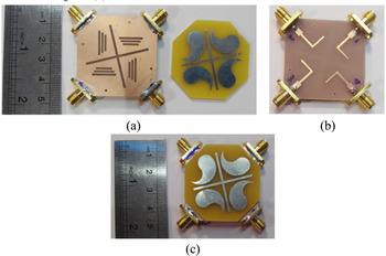
The presented four-element MIMO antenna is fabricated by using two FR4 substrates and four SMA connectors. The fabricated structure is demonstrated in Fig. 11. The upper and middle conductor layers in Fig. 11(a), lower conductor layer in Fig. 11(b), and final structure of the proposed antenna in Fig. 11(c) are shown.
Photographs of the fabricated antenna: (a) ground plane and Tai Chi-shaped patches, (b) antenna feed lines, and (c) final structure of the proposed four-element MIMO antenna.

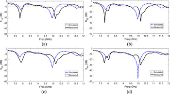
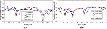
To measure the antenna's performance an Agilent network analyzer (E8363C) is used. The simulated and measured return loss responses for the proposed MIMO antenna at four ports are represented in Fig. 12 separately. Measured results indicate that the four-element MIMO antenna has IBWs of 7.58–8.04 GHz and 9.23–10.79 GHz for port-1, 7.56–8.12 GHz and 9.32–10.75 GHz for port-2, 7.48–7.96 GHz and 9.24–10.89 GHz for port-3, and 7.54–8.15 GHz and 9.28–10.61 GHz for port-4, which is suitable for X-band applications. It has been proven that excellent isolation between the MIMO antenna elements improves the system performance. Sij responses, where Sij denotes the S-parameter for ith antenna and jth antennas, are a way to show how much the MIMO antenna elements are isolated from each other. Figure 13 displays the simulated and measured isolations of the four-element MIMO antenna between orthogonal ports (Fig. 13(a)), and parallel ports (Fig. 13(b)). Due to the measured results, the isolation between the elements in this work is better than −20 dB.
Simulated and measured return loss responses for the proposed MIMO antenna, (a) S 11, (b) S 22, (c) S 33, and (d) S44.

Simulated and measured isolations between the proposed MIMO antenna ports: (a) orthogonal ports and (b) parallel ports.

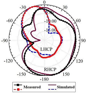
Also, the simulated and measured ECC, peak gain, and ARBW of the proposed antenna are illustrated in Figs 14 and 15, respectively. The numerical and experimental results are in good agreement. According to the measured results, the ECC for orthogonal and parallel ports of the antenna is <0.003 and 0.005, respectively, in the operating frequency band. Furthermore, the proposed antenna has a wide ARBW from 9.75 to 10.41 GHz and the average realized peak gain of 2 dBic. As well, the simulated and measured normalized RHCP and LHCP radiation patterns of the proposed MIMO antenna at 10 GHz for port-1 are demonstrated in Fig. 16. According to the surface current distribution over the Tai Chi-shaped patch, at 10 GHz, it is clear that the surface currents with phases of 0°, 90°, 180°, and 270° have a CW rotation on the patch. So the RHCP is the dominant polarization of the antenna. This is can be observed from the antenna radiation patterns. According to the patterns, it is shown that the RHCP radiation overcomes to LHCP radiation. The simulated antenna efficiencies for the four ports of the MIMO antenna are presented in Fig. 17.
Simulated and measured ECC between the proposed MIMO antenna ports: (a) orthogonal ports and (b) parallel ports.

Simulated and measured (a) peak gain and (b) ARBW of the proposed MIMO antenna for port-1.

Simulated and measured normalized radiation patterns of the proposed MIMO antenna at 10 GHz for port-1.

Simulated antenna efficiencies at the four ports.

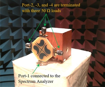
As shown in this figure, the simulated efficiencies at Port 1–4 are approximately 62% at 10 GHz frequency. The setup for radiation pattern measurement is shown in Fig. 18. In the measurement procedure, the port-1 is connected to an LG spectrum analyzer (SA-970) and the other ports are terminated with 50 Ω loads. The slight discrepancy between the simulated and measured results may be attributed to human errors and fabrication tolerances. Finally, to show the antenna advantages, two tables are given in this section. So, details of a fair comparison between the proposed four-element MIMO antenna and some recently similar designs are tabulated in Table 1. It is observed that the proposed antenna has two frequency band with a low correlation between the ports and compact size. Also, the proposed antenna has CP performance on the second frequency band, in a way that other designs do not have CP.
Photograph of the proposed MIMO antenna in the RF anechoic chamber.

Comparison between the proposed four-element MIMO antenna and some similar recent designs.

Ρ, correlation coefficient; ECC, envelop correlation coefficient; PG, realized peak gain; IBW, impedance bandwidth; ARBW, axial ratio bandwidths; MIMO, multiple-input multiple-output.
Moreover, the performance of the proposed antenna is compared with other designs, which employed Tai Chi-shaped structures in Table 2. According to this table, the proposed antenna exhibits a MIMO structure innovatively.
Comparison between the proposed antenna with Tai Chi-shaped patches and some similar works which use Tai Chi-shaped structures.

PG, realized peak gain; IBW, impedance bandwidth; ARBW, axial ratio bandwidths; MIMO, multiple-input multiple-output.
Conclusion
A new design of circularly polarized MIMO antenna is investigated in this work. By employing Tai Chi-shaped patch with L-shaped feed, the CP performance is realized in this design. The proposed MIMO antenna in this study is composed of three conducting layers separated by two 1.6 mm-thickness FR4 substrates. The lower substrate comprises four L-shaped microstrip feed lines and a ground plane. Also, the upper substrate includes four Tai Chi-shaped patches on the top side, which is put over the lower substrate and fixed there. Moreover, three rectangular-shaped slots are etched under each patch on the ground plane to produce an aperture coupled structure. The rectangular-shaped slots cover the patch surface above the L-shaped feed. The proposed four-element MIMO antenna has two resonant frequencies, the first at around 7.75 GHz and the second one with CP radiation at about 10.15 GHz. The minimum measured isolations between antenna ports is at least 20 dB with 46.7 × 46.7 mm2 total dimensions. Finally, the antenna is manufactured and tested with a good agreement between the simulations and measurements. The proposed design is suitable for X-band applications.
Acknowledgement
The authors would like to thank the Northwest Antenna and Microwave Research Laboratory (NAMRL) at Urmia University for technical supports.
 Ali Eslami was born in Zanjan, Iran in 1991. He received his B.Sc. in Information and Communication Technology Engineering from Roozbeh Institute of Higher Education, Zanjan, Iran in 2013 and M.Sc. degree in Electrical – Telecommunications from Urmia University, Urmia, Iran in 2019. Since 2019, he is researching on antenna species and his areas of interest are antenna design, microstrip antennas, and antenna's polarization species.
 Javad Nourinia received his B.Sc. in Electrical and Electronic Engineering from Shiraz University and M.Sc. degree in Electrical and Telecommunication Engineering from Iran University of Science and Technology, and Ph.D. degree in Electrical and Telecommunication from University of Science and Technology, Tehran, Iran in 2000. From 2000 he was an assistant professor and now he is a professor in the Department of Electrical Engineering of Urmia University, Urmia, Iran. His primary research interests are in antenna design, numerical methods in electromagnetic, and microwave circuits.
 Changiz Ghobadi was born in Iran on June 1, 1960. He received his B.Sc. in Electrical Engineering-Electronics and M.Sc. degrees in Electrical Engineering from Isfahan University of Technology, Isfahan, Iran and Ph.D. degree in Electrical- Telecommunication from University of Bath, Bath, the UK in 1998. From 1998 he was an assistant professor and now he is a professor in the Department of Electrical Engineering of Urmia University, Urmia, Iran. His primary research interests are in antenna design, radar and adaptive filters.
 Majid Shokri was born in Urmia, Iran in 1979. He received the B.Sc. and M.Sc. degrees from the Urmia Branch, IAU and Urmia University in 2001 and 2012, respectively, both in electrical and communication engineering. Since 2018 he is pursuing the Ph.D. degree in communication engineering with the Department of Electrical Engineering, Urmia University. His areas of interest are microstrip antennas, circularly polarized antennas and microwave circuits.