1. INTRODUCTION
Particle laser-acceleration is currently an active field of research, stimulated by the continued progress made in laser technology (Yanovsky et al., Reference Yanovsky, Chvykov, Kalinchenko, Rousseau, Planchon, Matsuoka, Maksimchuk, Nees, Cheriaux, Mourou and Krushelnick2008) and the need for machines that are more compact and less costly than the conventional accelerators. Many schemes and a number of different accelerator configurations have been suggested and investigated both theoretically (Scully & Zubairy, Reference Scully and Zubairy1991; Umstadter et al., Reference Umstadter, Kim, Esarey, Dodd and Neubert1995; Esarey et al., Reference Esarey, Sprangle and Krall1995; Salamin et al., Reference Salamin, Faisal and Keitel2000; Reference Salamin, Harman and Keitel2008; Wang et al., Reference Wang, Ho, Yuan, Kong, Cao, Sessler, Esarey and Nishida2001; Pang et al., Reference Pang, Ho, Yuan, Cao, Kong, Wang, Shao, Esarey and Sessler2002; Salamin & Keitel, Reference Salamin and Keitel2002; Kawata et al., Reference Kawata, Kong, Miyazaki, Miyauchi, Sonobe, Ssksi, Nakajima, Masuda, Ho, Miyanaga, Limpouch and Andreev2005; Salamin, Reference Salamin2006; Xu et al., Reference Xu, Kong, Chen, Wang, Wang, Lin and Ho2007; Xie et al., Reference Xie, Wang, Zheng, Zhang, Kong, Ho and Wang2010) and experimentally (Malka et al., Reference Malka, Lefebvre and Miquel1997; Shao et al., Reference Shao, Cline, Ding, Ho, Kong, Xu, Pogorelsky, Yakimenko and Kusche2013; Plettner et al., Reference Plettner, Byer, Colby, Cowan, Sears, Spencer and Siemann2005; Sears et al., 2005). The idea of employing a chirped pulse in laser acceleration has been suggested relatively recently (Singh, Reference Singh2005; Sohbatzadeh et al., Reference Sohbatzadeh, Mirzanejhad and Ghasemi2006; Reference Sohbatzadeh, Mirzanejhad and Aku2009; Reference Sohbatzadeh, Mirzanejhad, Aku and Ashouri2010; Reference Sohbatzadeh and Aku2011; Gupta & Suk, Reference Gupta and Suk2007; Galow et al., Reference Galow, Salamin, Liseykina, Harman and Keitel2011; Salamin, Reference Salamin2012). The basic mechanism at work in this scheme hinges on the fact that chirping the frequency distorts the pulse and generates a quasi-static electric field portion which, in turn, gives the particle, e.g., an electron, a substantial boost. In other words, the electron moves synchronously with the pulse by surfing over this low-frequency portion and gains energy continuously from it. The scheme, as such, works to accelerate electrons from rest, and can be useful as a booster, too.
Several papers have been written on acceleration by a chirped pulse, mostly presenting numerical results. In this paper, the aim is two-fold. Efforts will be invested here to find out how much progress can be achieved by pursuing the analytic investigations. It is always good to develop the equations that guide our thinking about the physics and also help us benchmark the numerical simulations, which will ultimately be resorted to, to handle a real accelerator configuration. The second, intimately related, aim of this work is to some extent pedagogical. It is hoped that detailed investigation of the various dynamical aspects of the process will shed new and much needed light onto the mechanism of acceleration by a chirped pulse (Galow et al., Reference Galow, Salamin, Liseykina, Harman and Keitel2011).
The basic theory and main working equations will be presented in Section 2. In the same section, the equations will be used to investigate the dynamics of a single electron injected axially for subsequent interaction with a chirped pulse. The parameters used in this investigation are the same as those used elsewhere (Hartemann et al., Reference Hartemann, Fochs, Sage, Luhmann, Woodworth, Perry, Chen and Kerman1995) albeit employing a non-chirped pulse. The purpose is to show that both investigations agree in the appropriate limits. Details of the investigation of acceleration configurations of electrons initially at rest at the origin of coordinates, axially injected, and injected sideways at some angle with respect to the propagation direction of the pulse, will be presented in Section 3. Finally, a summary and the main conclusions will be given in Section 4.
2. BASIC THEORY
The theoretical background of laser acceleration by a chirped plane-wave laser pulse will be briefly described in this section. A particular case of axial injection will be discussed in some detail and the results of our calculations will be shown to have the correct limits of acceleration by the corresponding unchirped pulse (Hartemann et al., Reference Hartemann, Fochs, Sage, Luhmann, Woodworth, Perry, Chen and Kerman1995).
2.1. General
In the main working equations for the dynamics of a single electron in chirped plane-wave laser fields, the electron is treated as a point particle of mass m and charge −e, the relativistic energy and momentum are given, respectively, by ε = γmc 2 and  $ \vec{p}= \gamma mc \vec{\rm \beta}$, where
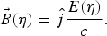
 $\vec{\rm \beta}$ is the velocity of the particle scaled by c, the speed of light in vacuum, and γ = (1 − β2)−1/2. The fields, on the other hand, are modeled by an infinite plane-wave and a finite-duration plane-wave pulse. In modeling those fields the combination η = ω0t − k 0z, in which ω0 is the initial (unchirped) frequency and k 0 = 2π/λ0 is the wavenumber, is used as a variable. Thus, the chirped frequency is ω = ω0(1 + bη), where b is the dimensionless chirp parameter. We work with the fields (SI units)
 $$\vec{E} \lpar {\rm \eta} \rpar = \hat iE_0 \sin\lpar {\rm \eta} + b{\rm \eta} ^2 \rpar \cos^2 \left[{\displaystyle{{\rm \pi} \over {{\rm \tau \omega}_0 }}\lpar {\rm \eta} - \bar {\rm \eta} \rpar } \right]\comma \;$$
 $$\vec{B} \lpar {\rm \eta} \rpar = \hat j\displaystyle{{E\lpar {\rm \eta} \rpar } \over c}.$$
These equations model the fields of a pulse with a cos2 envelope, a temporal width τ = 50 fs, a wavelength λ0 = 1 μm, provided the choice  $\bar {\rm \eta} = 15{\rm \pi}$ is made. For an electron interacting with an infinite plane wave, the normalized field strength a = eE 0/mcω0 is related to the laser field intensity I by
 $a = e\sqrt {2I/c {\rm \varepsilon} _0 } /\lpar mc{\rm \omega} _0 \rpar $, where ε0 is the permittivity of free space and λ0 is the wavelength of the unchirped laser field. Inserting values of the universal constants, one gets
 $$I\left[{\displaystyle{{\rm W} \over {{\rm cm}^2 }}} \right]= 1.36817 \times 10^{18} \mathop {\left[{\displaystyle{a \over {{\rm \lambda}_0 [{\rm \mu m}] }}} \right]}\nolimits^2 \comma \;$$
thus making a 2 a dimensionless intensity parameter.
In the next two subsections, two sets of conditions on the initial injection position and velocity of the electron will be considered. Section 2.2 will be devoted to the axial injection configuration, while the more general case of electron injection at an angle ζ0 to the pulse propagation direction, will be taken up in Section 2.3. Various aspects of the electron dynamics will be discussed, including evolution of its kinetic energy and velocity components, as well as its trajectories. In order to be able to tackle the general injection situation, for which some of the analytic solutions become too cumbersome, we will resort here to numerical integration of the combined equations of motion
 $$\displaystyle{{d \vec{\rm \beta}} \over {dt}} = \displaystyle{e \over {{\rm \gamma} mc}}\left[{ \vec{\rm \beta} \lpar \vec{\rm \beta} \cdot \vec {E} \rpar - \lpar \vec{E} + c\vec{\rm \beta} \times \vec{B} \rpar } \right].$$
Instead of working directly with the time t as a variable, we will employ η. The integration limits will be denoted by ηi and ηf. Equation (4) is equivalent to three coupled differential equations. This system of differential equations has been solved numerically using Runge-Kutta-based Mathematica codes we have developed over the years. All of our results have independently been confirmed by codes written in Python, as well.
2.2. Axial Injection
In Salamin (Reference Salamin2012), the special case corresponding to ζ0 = 0 (axial injection) was briefly discussed. Much of the discussion there was based on the analytic solution to the Newton-Lorentz equations. Issues pertaining to this particular case not covered in Salamin (Reference Salamin2012) will be discussed here for completeness and in order to demonstrate that the results obtained in the chirped pulse have their correct unchirped limits published elsewhere (Hartemann et al., Reference Hartemann, Fochs, Sage, Luhmann, Woodworth, Perry, Chen and Kerman1995).
For the initial conditions on particle injection, the assumption will be made that the front of the pulse catches up with the MeV electron at t = 0, precisely at the origin of coordinates (x 0 = y 0 = z 0 = 0). Hence, ηi = 0 and ηf = 30π for the cos2 pulse described above. Furthermore, the electron is assumed to be traveling axially (along the direction of propagation of the pulse, the z-axis) with a scaled speed β0, derived from γ0 = 10, which corresponds to the initial injection kinetic energy K 0 ~ 4.6 MeV. For an unchirped laser pulse of field intensity I ~ 1.23 × 10¹⁹ W/cm2 (a = 3), this configuration has been discussed thoroughly elsewhere (Hartemann et al., Reference Hartemann, Fochs, Sage, Luhmann, Woodworth, Perry, Chen and Kerman1995). What we will do below is investigate the same electron dynamics, albeit in a chirped laser pulse. The results will be displayed along with their unchirped counterparts, so that visual comparison may be facilitated.
To begin with, Figure 1a shows the unchirped scaled electric field of the pulse vs. η. Figure 1c shows how this field gets distorted when the frequency is chirped using b = −0.0103. The pulse develops an asymmetrical low-frequency, indeed quasi-static, part. In Figure 1b, evolution with η of the kinetic energy of the electron is shown for b = 0. As expected from the Lawson-Woodward theorem (Woodward, Reference Woodward1947; Lawson, Reference Lawson1979) the electron gains no net energy from interaction with the plane-wave unchirped pulse. Substantial gain, however, is shown in Figure 1d to result from synchronous interaction with the low-frequency part of the chirped pulse. As expected, too, interaction with the wings, whose frequency is minimally affected by the chirp, results in very little or no further energy gain at all.
(a) Evolution of the normalized unchirped (b = 0) electric field of a cos2 laser pulse of duration τ = 50 fs. (b) Evolution of the electron kinetic energy during interaction with the unchirped pulse. (c) and (d): Same as (a) and (b), respectively, but for a chirped laser pulse (b = −0.0103). The remaining parameters are: λ0 = 1 μm, a = 3 (intensity I ~ 1.23 × 10¹⁹ W/cm2) and γ0 = 10 (injection kinetic energy K 0 ~ 4.6 MeV).

As has been shown elsewhere (Hartemann et al., Reference Hartemann, Fochs, Sage, Luhmann, Woodworth, Perry, Chen and Kerman1995; Salamin, Reference Salamin2012), in the case of axial injection, the trajectory of the electron is confined to the xz–plane, the polarization plane of the laser pulse. Instead of showing the xz trajectory, Figure 2 displays evolution of the x– and z– coordinates, separately, with η. By comparing the unchirped Figure 2a with the chirped Figure 2c one can read clearly the amount of net electron displacement, Δx as a result of interaction with the pulse (poderomotive scattering). For the parameter set used, Δx ~ 2 μm (unchirped) whereas Δx ~ 7.5 mm (chirped). Likewise, the corresponding axial excursions made by the electron during interaction with the pulse are: Δz ~ 8 mm (unchirped) and Δz ~ 3.8 m (chirped).
(a) and (b): Evolution of the transverse and axial position coordinates, respectively, as functions of the variable η, while interacting with an unchirped (b = 0) cos2 laser pulse of duration τ = 50 fs. (c) and (d):Same as (a) and (b), respectively, but for a chirped pulse (b = −0.0103). The remaining parameters are the same as in Figure 1.
Components of the electron scaled velocity vector are displayed in Fig. 3. Interaction with the unchirped pulse gives results identical to those obtained earlier (Hartemann et al., Reference Hartemann, Fochs, Sage, Luhmann, Woodworth, Perry, Chen and Kerman1995). Figures 3a and 3b show that the electron is left behind the pulse moving at exactly the same velocity with which it was injected initially, again as expected from the Lawson-Woodward theorem (Woodward, Reference Woodward1947; Lawson, Reference Lawson1979). By contrast, interaction with the chirped pulse results in clear particle acceleration, as shown in Figures 3c and 3d. The electron emerges from the interaction with a slight increase in its transverse velocity βx, while βz → 1.
(a) and (b): Evolution of the electron transverse and axial scaled velocity components, respectively, as functions of the variable η, while interacting with an unchirped (b = 0) cos2 laser pulse of duration τ = 50 fs. (c) and (d): Same as (a) and (b), respectively, but for a chirped pulse (b = −0.0103). The remaining parameters are the same as in Figure 1.
2.3. Sideways Injection
The axial injection configuration, discussed in Section 2.2, is probably difficult to realize experimentally. Assuming that the model itself is sound, a more practically-realizable configuration would be one in which the electron is injected in, for example, the yz–plane at an angle ζ0 with the laser pulse propagation direction, the z–axis. Thus, the initial injection velocity of the electron, scaled by the speed of light c, may be written as
 $$\vec{\rm \beta}_0= {\rm \beta} _0 \lpar - \hat j\sin {\rm \zeta} _0 + \hat k \cos{\rm \zeta} _0 \rpar.$$
Here, too, the assumption will be made that the front of the laser pulse catches up with the electron at t = 0 at the origin of coordinates. Every result to be presented below has been produced employing numerical codes which return the corresponding result discussed in Section 2.2 in the limit ζ0 → 0. More importantly, the following logical amendments to the working equations must be introduced (Salamin, Reference Salamin2012). Adopting Eq. (5) as the initial condition on the velocity requires that the constants of the motion be altered to read: c 1 = γβy = −γ0β0 sinζ0, and c 2 = γ(1 − βz) = γ0(1 − β0 cosζ0). Taking all of this into consideration, the scaled energy expression takes the form
 $${\rm \gamma} = \displaystyle{{1 + \lpar {\rm \gamma\beta} _x \rpar ^2 + \lpar {\rm \gamma}_0 {\rm \beta} _0 \sin{\rm \zeta} _0 \rpar ^2 + {\gamma}_0^2 \lpar 1 - {\rm \beta} _0 \cos{\rm \zeta} _0 \rpar ^2 } \over {2{\rm \gamma}_0 \lpar 1 - {\rm \beta} _0 \cos{\rm \zeta} _0 \rpar }}.$$
On the other hand, the general expression of γβx(η) stays the same (Salamin, Reference Salamin2012)
 $${\rm \gamma\beta} _x \lpar {\rm \eta} \rpar = a \int_{{\rm \eta} _0 }^{\rm \eta} \, \sin\lpar {\rm \eta} ^{\prime} + b\!\mathop {{\rm \eta} ^{\prime}}\nolimits^2 \rpar \cos^2 \left[{\displaystyle{{\rm \pi} \over {{\rm \tau \omega} _0 }}\lpar {\rm \eta} ^{\prime} - \bar {\rm \eta} \rpar } \right]d{\rm \eta} ^{\prime}.$$
Before investigating the electron dynamics in this general scenario, values of the chirp parameter b, appropriate for obtaining substantial acceleration, will have to be obtained. To this end, exit electron kinetic energies will be calculated as b is varied from −0.04 to zero. The results are shown in Figure 4, for the cases of axial injection (ζ0 = 0°) and sideways injection (at ζ0 = 10°). All other parameters are the same as in Section 2.2. The peaks in the figures occur at b values which result in optimal synchronous motion between the electron and the pulse. Conversely, total lack of synchronization leads to the appearance of the minima, which express zero net energy gain. Note that the absolute maximum in Figure 4, which has already been used in the case of axial injection, occurs at b ~ − 0.0103.
Electron exit kinetic energy, K exit ≡K(ηf) = [γ(ηf) − 1]mc 2, where ηf = 30π, vs. the chirp parameter, as a result of interaction with a chirped plane-wave laser pulse of a cos2 envelope and duration τ = 50 fs. The laser wavelength is λ0 = 1 μm, and a = 3 (I ~ 1.23 × 10¹⁹ W/cm2). Initial injection is at γ0 = 10 (K 0 ~ 4.6 MeV) axially (ζ0 = 0) and sideways at ζ0 = 10°. Onset of the interaction is assumed to have been at t = 0, the instant the electron passes through the origin of coordinates.
As it turns out, the plots of K exit vs. b, corresponding to the different cases of particle injection into the laser field, have the same structure and exhibit minima and maxima at precisely the same values of b, with all other parameters the same. The heights of the corresponding maxima, however, are different. For the chosen parameters, the exit kinetic energies associated with the configuration of sideways injection at ζ0 = 10° are roughly a factor of 4 smaller than those of the axial injection case.
The above conclusions should come as no surprise, in light of the following. To find the values of b that correspond to maximum exit kinetic energies, one sets equal to zero the derivative with respect to b of the expression of γ given in Eq. (6). This is tantamount to extremizing γβx with respect to b, Eq. (7). In fact, this process amounts to finding the zeros of the following function, obtained by differentiating with respect to b under the integral in Eq. (7)
 $$S\lpar b\rpar = \int_{{\rm \eta} _0 }^{\rm \eta} \, \mathop {{\rm \eta} ^{\prime}}\nolimits^2 \cos\lpar {\rm \eta} ^{\prime} + b\!\mathop {{\rm \eta} ^{\prime}}\nolimits^2 \rpar \cos^2 \left[{\displaystyle{{\rm \pi} \over {{\rm \tau \omega} _0 }}\lpar {\rm \eta} ^{\prime} - \bar {\rm \eta} \rpar } \right]d{\rm \eta} ^{\prime}.$$
Careful inspection of S(b) quickly reveals that it is independent of the initial velocity of the electron and the laser field intensity parameter a. Thus, those zeros as well as the maxima exhibited by the K exit vs. b plots, will always have the same general structure and the same b values at which the zeros of S(b) and maxima of K exit occur, provided the pulse-shape is the same. In other words, the positions of the maxima are model-dependent. The heights of the maxima, however, depend upon a 2, γ0 and ζ0. This is demonstrated in Figure 5 where, in addition to S(b), the exit kinetic energy is shown over the same range of b values for the case of an electron initially at rest at the origin. Vertical lines are added to indicate the zeros of S(b) and the corresponding exit kinetic energy maxima.
Same as Figure 4, but for electron initial conditions of rest at the origin of coordinates. Shown also is the function S(b) given by Eq. (8) whose zeros are the values of b corresponding to each of which the exit kinetic energy attained is a maximum. The vertical lines indicate the zeros of S and the exit kinetic energy maxima.
3. FURTHER ELECTRON DYNAMICS
In the investigations of the previous section, the parameters used were chosen for the purpose of comparing our results, in the limit of b → 0 (unchirped configuration) with known ones (Hartemann, Reference Hartemann, Fochs, Sage, Luhmann, Woodworth, Perry, Chen and Kerman1995), in addition to investigating the process of net energy gain from interaction with the chirped pulse. This section will be devoted to further investigations of the electron dynamics in chirped pulses employing a totally different, yet experimentally available, set of laser and electron parameters. The laser field intensity parameter will be taken as a = 10 (I ~ 1.37 × 10²⁰ W/cm2, at λ0 = 1 μm).
Here, too, situations corresponding to three different sets of initial conditions will be explored. Variations of K exit with b for all three cases are shown in Figure 6. As has been shown above, the same values of b locate the maxima of all cases. Axial injection results in best gains while less energy is gained when injection is made at ζ0 > 0. With increasing injection angle more energy is carried by the transverse degree of freedom, oscillation in the polarization direction of the laser pulse. Note also that the figure shows clearly that substantial energy is also gained in the case of initial rest at the origin. This configuration will be discussed in more details in the next subsection.
Same as Figure 4, but for a = 10 and electron initial conditions of rest at the origin of coordinates, and injection at γ0 = 5, for ζ0 = 0 and 5°.
3.1. Acceleration from Rest
In laser-assisted atomic ionization, an electron may be produced in a state of near rest (Hu & Starace, Reference Hu and Starace2002; Maltsef & Ditmire, Reference Maltsev and Ditmire2003). When subsequently subjected to the fields of the chirped pulse, such an electron may be accelerated in vacuum. If the front of the pulse reaches the point at which the electron is born at the same time, its subsequent dynamics will be dominated by the fields of such a pulse. This is clearly an idealized state of affairs and a probably difficult scenario to realize experimentally. Nevertheless, several aspects of the electron motion will be discussed here based on the solutions to the relativistic equations of motion.
Note first the synchronized rise in the kinetic energy of the electron in Figure 7, during interaction with the part of the pulse that has been distorted by the chirp. That accelerating part of the pulse witnesses a substantial decrease in the frequency due to the negative chirp. The electron interacts with an essentially quasi-static electric field and gains about 4.53841 GeV from it, for the parameter set used and b = −0.01. Interaction with the higher frequency parts of the pulse results in no further energy gain or loss.
Evolution in η of the normalized electric field strength, E x/E 0, of a chirped (b = −0.01) cos2 laser pulse of 50 fs duration, and the kinetic energy, K, of a single electron interacting with it. The field intensity is I ~ 1.37 × 10²⁰ W/cm2 (a = 10, λ0 = 1 μm). Initial conditions are those of rest at the origin of coordinates.
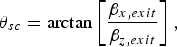
Figure 8 shows the x– and z–components of the velocity of the electron, scaled by c, while it is interacting with the pulse. In the absence of a force y–component, the electron motion is confined to the xz–plane and, thus, a βy is absent. Note that during the initial stage of interaction with the pulse, βx only rises, due to the x–component of the force exerted by the laser's oscillatory electric field. Soon after that, the z–component of the v→ × B→ force of the laser begins to impart axial kicks to the electron. Thus, while βx continues to exhibit essentially equal-amplitude oscillations for a while, βz oscillates between zero and an increasing positive value which approaches unity quickly as the electron is left behind the pulse. Note that the exit value of βx is nonzero, which shows that the electron will suffer net deflection from pure axial motion (ponderomotive scattering). A scattering angle, indicating the direction in which the electron will emerge after interaction with the pulse has ceased, may be defined by
Evolution in η of the components, βz and βx, of the velocity vector, normalized by the speed of light in vacuum, of the electron whose kinetic energy is shown in Figure 7.
 $${\rm \theta} _{sc} = \arctan\left[{\displaystyle{{{\rm \beta} _{x\comma exit} } \over {{\rm \beta} _{z\comma exit} }}} \right]\comma \; $$
where βx,exit = βx(ηf) and βz,exit = βz(ηf). Using the exit values βx(ηf) ~ 0.0150046 and βz(ηf) ~ 0.999887 results in a scattering angle of θsc ~ 0.859732°.
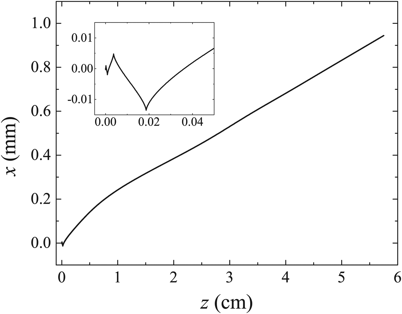
As has just been pointed out, the electron trajectory, while interacting with the laser pulse, is two-dimensional (in the xz–plane). A sample trajectory is shown in Figure 9. Initial interaction with the linearly-polarized pulse results in the familiar structure shown in the inset. After these initial oscillations the electron follows an essentially straight-line trajectory while interacting with the quasi-static part of the electric field. For the parameter set employed, the calculation returns exit transverse and axial excursions Δx ~ 0.944792 mm, and Δz ~ 5.75264 cm, respectively.
Two-dimensional trajectory of the single electron whose kinetic energy is shown in Figure 7. The inset is a zoom-in on the part of the trajectory which results from interaction with the first few laser cycles.
Performance of a conventional accelerator is often indicated by quoting its average acceleration gradient. An estimate of this quantity may be obtained by dividing the exit kinetic energy (see Fig. 7) by the exit axial excursion (see Fig. 9)
 $$\bar G \equiv \displaystyle{{\Delta K} \over {\Delta z}}\comma \;$$
where ΔK = K(ηf) − K(η0) and Δz = z(ηf) − z(η0). For example, a natural limit of ~ 100 MeV/m exists on the average gradient of a conventional electron linear accelerator. For the electron accelerated from rest by the present scheme, our results show that  $\bar G \sim78.8926$ GeV/m, or close to three orders of magnitude times the conventional limit.
3.2. Acceleration from Axial Injection
An already fast electron, pre-accelerated by a table-top linear accelerator or an electron gun, may be subjected to a static magnetic field in order to bend its trajectory prior to shining the laser pulse on it. This can approximate the case of axial injection, to be discussed here. Again, the assumption is made that the front end of the pulse will catch up with the electron at t = 0, exactly at the origin of the coordinate system. Following the pattern of the previous subsection, the normalized electric field of the high-intensity chirped pulse is shown in Figure 10, together with the evolving kinetic energy of the electron during interaction. In addition to exhibiting the same general features as in Figure 7, Figure 10 shows an increase in the electron's kinetic energy from K 0 ~ 2.044 MeV (γ0 = 5) to K exit ~ 44.9277 GeV, or more than four orders of magnitude.
Same as Figure 7, but for an electron injected axially with an initial kinetic energy K 0 ~ 2.044 MeV (γ0 = 5).
Evolution of the electron's velocity during interaction with the chirped pulse is shown in Figure 11. Here, too, subsequent motion is two-dimensional (in the polarization plane of the laser). As for the case of acceleration from rest, βx starts from zero due to the strong action of the oscillating E x of the laser pulse on it and oscillates between roughly –0.1 and 0.1. Upon exit from the interaction region βx ~ 0.00151586. On the other hand, βz starts from a relativistic value, oscillates for some time between that value and an increasing maximum, due to the combined action of E z and (ν→ × B →)z, and finally approaches unity as a result of interaction with the quasi-static electric field. It is eventually left behind the pulse moving at βz ~ 0.999999.
Same as Figure 8, but for axial injection with γ0 = 5.
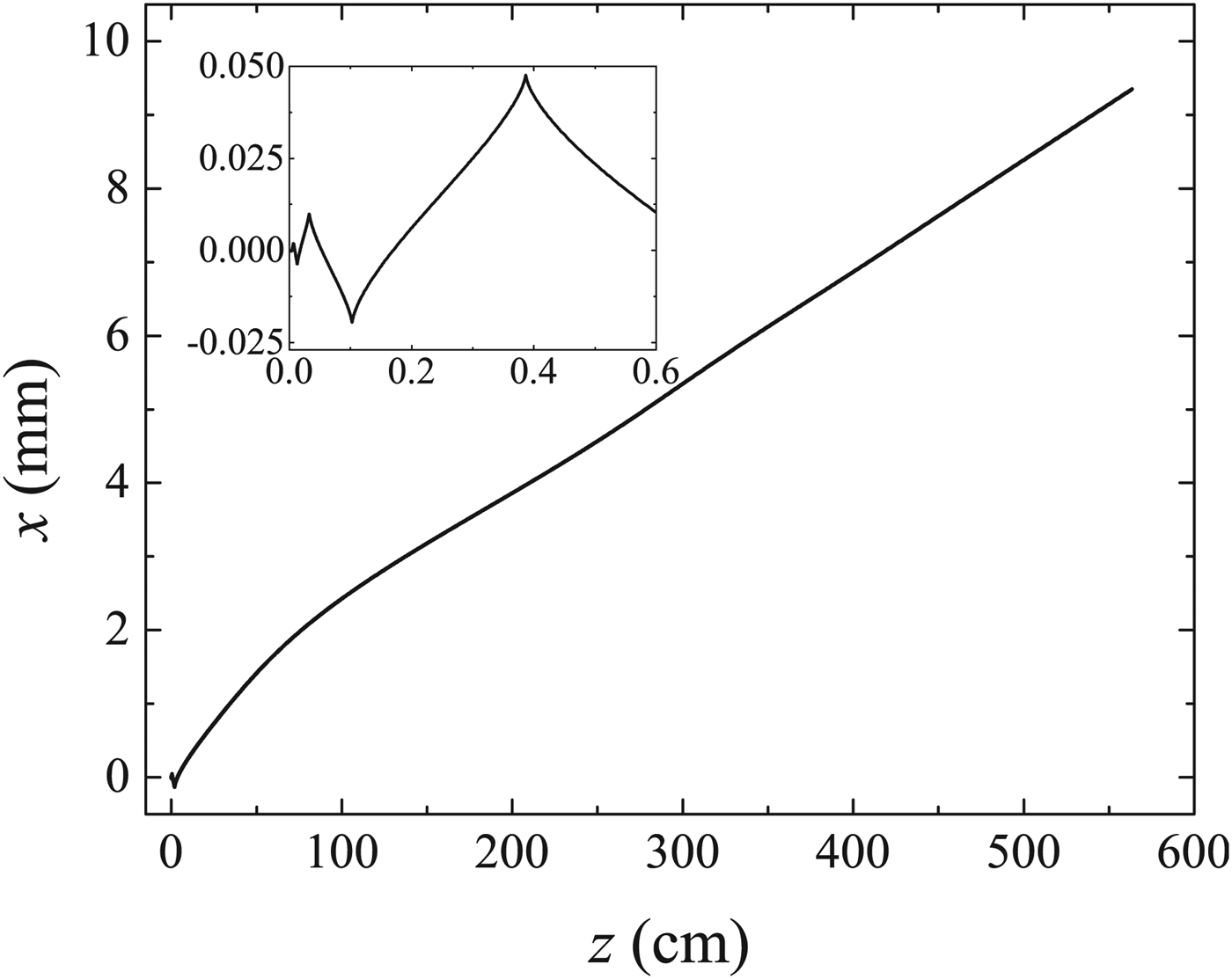
Finally, the two-dimensional trajectory for the case of axial injection is shown in Figure 12. The trajectory looks similar in overall features to the corresponding one displayed in Figure 9 for the case of acceleration from rest. The dimensions in this case, however, are roughly 10-fold transversely and a hundred-fold axially, as a result of the initial forward momentum. Note that the electron undergoes the transverse and axial displacements Δx ~ 9.35248 mm and Δz ~ 5.63773 m, respectively. The latter, when combined with K exit ~ 44.9277 GeV, yields  $\bar G$ ~ 7.96911 GeV/m. Note further that, although the case of axial injection results in roughly ten times overall exit kinetic energy for the electron, compared with the case of initial rest at the origin, the acceleration gradient is almost ten times less in the latter case compared with the former. The initial forward momentum results in a much larger axial excursion, in this case, than in the case of acceleration from rest.
Same as Figure 9, but for axial injection with γ0 = 5.
3.3. Acceleration from Sideways Injection
It seems much easier, from an experimental perspective, for the electron to be injected sideways (at an angle ζ0 with respect to the direction of pulse propagation). This configuration will be discussed next. The injected electron has initial transverse and axial momenta. Thus, its subsequent motion will not be confined to the xz–plane. In fact, the trajectory will be three-dimensional, in spite of the fact that the initial injection is made within the xz–plane. This is due to the influence of the magnetic field of the laser pulse. Discussions will now be presented of the case of injection at γ0 = 5, but at the angle ζ0 = 5°.
The normalized electric field of the pulse and evolution of the kinetic energy of the electron are shown in Figure 13. The fact that the electron, in this case, is injected with less initial axial momentum, than in the case of purely axial injection when the same parameters are used, will result in lower exit kinetic energy for the accelerated electron; see Eq. (6). The exit kinetic energy that may be read off of Figure 13 is about 38 GeV, compared to ~ 45 GeV for an axially injected electron.
Same as Figure 7, but for an electron injected sideways at the angle ζ0 = 5° with the direction of pulse propagation, and an initial kinetic energy K 0 ~ 2.044 MeV (γ0 = 5).
Components of the scaled velocity vector β are shown in Figure 14. As expected, βx starts initially from a value of zero, oscillates during interaction and retains a small exit value, ~ 0.00179557 for the parameter set employed. On the other hand, the y– and z–components, βy and βz, have nonzero initial values, which help them accumulate successive increases after interaction with every laser cycle. Partly due to the fact that the injection angle is too small and, hence, the initial value of βz is greater than that of βy, the exit values of these two components are widely different (βy → − 5.75237 × 10⁻⁶ and βz → 0.999998). Using the exit values of βx and βz in Eq. (9) gives θsc ~ 0.102879°. In conclusion, the electron emerges from interaction with the pulse essentially axially.
Same as Figure 11, but for an electron injected sideways at the angle ζ0 = 5° with the direction of pulse propagation, and an initial kinetic energy K 0 ~ 2.044 MeV (γ0 = 5).
Sideways injection of the electron leads to the three-dimensional trajectory shown in Figure 15. Details of the part of that trajectory which result from interaction with the first few laser cycles are displayed in Figure 15b. The existence of turning points in the x– and y–coordinates is quite evident. More clearly pronounced is the forward drift in z. The following exit coordinates have been calculated: x exit ~ 7.89547 mm, y exit ~ − 53.5223 μm, and z exit ~ 4.01806 m. Therefore, using the calculated exit kinetic energy of K exit ~ 37.9288 GeV, Eq. (10) yields  $\bar G$ ~ 9.43905 GeV/m, or about two orders of magnitude better than the limit of a conventional linear accelerator.
Three-dimensional trajectory of a single electron submitted to a chirped laser pulse (b =− 0.01). In (b) we zoom-in on part of the trajectory followed during roughly the first one-third of the interaction time with the pulse. Injection is at ζ0 = 5° and γ0 = 5 (K 0 ~ 2.044 MeV). The laser parameters are: a = 10, λ0 = 1 μm, and τ = 50 fs.
4. DISCUSSION AND CONCLUSIONS
Dynamics of a single electron submitted to a high-intensity chirped laser pulse has been the subject of investigation in this work. The aim has been mainly pedagogical: to gain more insight into the process of electron acceleration by a chirped laser pulse. A simple plane-wave model representation of the electromagnetic fields of the pulse has been employed. Three different initial conditions on the position and velocity of the electron have been considered: rest at the origin, injection axially and injection at an angle ζ0 relative to the direction of pulse propagation. Working equations of general applicability have been derived and used directly to study some aspects of the electron dynamics, or else have served as a basis for benchmarking the numerical simulations that were conducted to investigate further more sophisticated aspects.
The case of axial injection has been taken up first, using parameters the same as ones employed in a similar study, albeit for a non-chirped laser pulse (Hartemann et al., Reference Hartemann, Fochs, Sage, Luhmann, Woodworth, Perry, Chen and Kerman1995). The aim has been to show that our chirped-pulse-based investigations would produce the same results in the appropriate limit, both analytically and numerically. This aim has been fully accomplished.
Then more thorough investigations were conducted, which typically started by scanning a small portion of the chirp parameter space for values that would lead to sizable energy gains by the electron from interaction with the pulse. It has been shown that the chirp parameter values which lead to maximum gain are not affected by the change of conditions on the electron initial injection. The same values of b maximize the gain in all considered configurations.
In an actual experiment, one would be interested in a number of important details, such as the actual trajectory, the ejection dynamics and, most importantly, the exit kinetic energy of the electron. In our single-particle calculations, synchronous motion of the electron, which is believed to be responsible for the energy gain, has been demonstrated by showing evolution of its kinetic energy in a typical event together with the normalized electric field seen by it. It has been shown, in all cases considered, that substantial energy gain takes place always during interaction with a quasi-static part of the field generated by chirping the pulse frequency appropriately.
Evolution of the velocity components during interaction have been studied. More importantly, the exit electron velocities were found in each example and a scattering angle has been calculated. In all cases, the particles were found to be ejected within a small cone about the propagation direction of the pulse. In other words, while this demonstrates ponderomotive scattering, it also predicts that a bunch or beam of electrons would suffer little spatial diffraction.
To gain further insight into the particle-field interactions, actual trajectories for the various investigated events have been calculated. Straightforward arguments, based on the general equations of motion, led to the conclusion that the trajectories in the cases of acceleration from rest at the origin or from axial injection would be two-dimensional, motion of the electron would be confined to the polarization plane of the pulse. Sideways injection, however, has been shown to lead to three-dimensional trajectories.
Finally, it should be borne in mind that the model adopted in this work is plane-wave in character. As such, some of the results may turn out to be overly exaggerated. The kinds of laser peak intensities used in our calculations can only be reached by tightly focused pulses. As is well known, a tightly focused gaussian beam, for example, is plane-wave in character only on the focal plane or else too far away from such a plane. Thus, the energy gains of several tens of GeV and the acceleration gradients of a few GeV/m, predicted in this work, may be overestimates of what is expected to emerge from a more realistic model, like that of a tightly focused gaussian pulse.
ACKNOWLEDGMENT
YIS acknowledges support for this work from an American University of Sharjah Faculty Research Grant (FRG-III).