Introduction
A reflectarray antenna is merging of reflector and phased-array antennas [Reference Huang and Encinar1]. To keep low costs, reflector antennas are usually preferred for movable and fixed terminals. However, the complexity and cost of the reflectors increase for different transmit and receive frequencies [Reference Chang and Hanlin2]. To solve this problem, an easy solution is based on the use of a horn with dual-frequency characteristic, but this technique has the drawback of leading to a reduction in the antenna gain, since the horn phase center would be placed at a different position for each operating frequency. By using microstrip reflectarray technology, low-profile, cost-effective, and light volume antennas can be obtained [Reference Huang and Encinar1]. The size, shape, and position of each reflectarray element must be adjusted through an accurate design process in order to convert the incident electric field radiated by the feed-horn in a plane wave-front in the desired outgoing direction [Reference Huang and Encinar1].
One of the main characteristics of reflectarray antennas is that they can be designed to work at multiple frequency bands, either using a single-layer [Reference Abdollahvand, Encinar, Forooraghi, Atlasbaf and Barba3–Reference Su, Yi and Wu9] or a stacked multi-layer configuration [Reference Martinez-de-Rioja, Encinar, Barba, Florencio, Boix and Losada10–Reference Encinar and Barba14]. Single-layer reflectarrays offer a reduced manufacturing cost; however, the physical distance between the unit-cell elements used for each frequency band may seem a design problem, since the mutual coupling between the elements must be accurately taken into account and physical interference must be avoided [Reference Huang and Encinar1, Reference Hasani and Peixeiro5]. In the case of dual-band reflectarrays based on several stacked layers, the restriction of this method is that cells with identical period are applied for both frequency bands, and as a result, the maximum ratio between the two frequencies is limited [Reference Encinar13]. Thus, a reflectarray antenna can be designed for transmit and receive at two different frequencies, either using a feed with dual-frequency characteristic [Reference Zarghani and Atlasbaf7] or applying separate feeds for each frequency band [Reference Martinez-de-Rioja, Encinar, Barba, Florencio, Boix and Losada10]. In both cases, the reflectarray can be designed to work in dual polarization [Reference Chen, Chen, Wang, Gu and Shi4, Reference Zarghani and Atlasbaf7, Reference Martinez-de-Rioja, Encinar, Barba, Florencio, Boix and Losada10].
Our goal in this paper is to present the design, fabrication, and testing of a new dual-polarized and dual-band printed reflectarray with application to Satcom terminal antennas in the Ka-band (20/30 GHz). The designed single-layer reflectarray is composed of a new unit-cell element that includes a crossed dipole with four modified truncated rings for 30 GHz, and a cross-shaped loop for 20 GHz. The reflectarray antenna has been designed to produce an independently focused beam at 20 and 30 GHz in dual polarization, by means of an independent adjustment of the unit-cell parameters used to control the phase response at each operating frequency [Reference Martinez-de-Rioja, Encinar, Barba, Florencio, Boix and Losada10]. The antenna has been illuminated by two separate feed horns, one for each frequency band. The designed reflectarray has a simple structure with the significant advantages of being dual-polarized, single-layer, and showing independent implementations at two separated frequency bands.
Dual-frequency reflectarray cells
In this section, we provide the simulation results of our proposed unit-cell structure, which is presented in Fig. 1. When designing the unit cell, our objective was to combine different types of resonant elements in a single-reflectarray layer, so that each group of elements will be used to control the reflection phase response of the cell at a different operating frequency. The proposed unit cell is composed of a crossed dipole with four truncated rectangular rings for operation at 30 GHz, and a cross-shaped loop for operation at 20 GHz. The three types of resonant elements have been used separately in previous studies about single-layer reflectarrays, where cross loops [Reference Chaharmir, Shaker and Legay15], crossed dipoles [Reference Chen, Chen, Wang, Gu and Shi4], or truncated rings [Reference Smith, Gothelf, Kim and Breinbjerg6, Reference Han and Chang16] are employed as the phasing elements. The novelty of this paper is to combine the previous elements to obtain a new single-layer reflectarray cell for operation in dual polarization at two separate frequencies (20 and 30 GHz). This process has involved some trials in order to achieve the most suitable arrangement of the printed elements. The lower-frequency elements have been arranged with a half-a-period shifting with respect to the higher-frequency elements in both the horizontal and vertical axes, in order to avoid overlaps and provide enough space for all the elements. The resulting layout for the proposed periodic cell configuration is shown in Fig. 1.
Configuration and parameters of the proposed reflectarray cell (gray lines are metal).

The unit cell has been designed assuming an Arlon CuClad 217™ substrate with loss tangent tan δ = 0.0009, relative permittivity εr = 2.17, and thickness h sub = 0.762 mm. To avoid the emersion of grating lobes [Reference Huang and Encinar1], the dimensions of the unit cell have been defined as 5 × 5 mm2 (λ/2 at 30 GHz). By using Ansoft HFSS, the proposed cell structure in an infinite array environment has been analyzed to select the optimum values of the geometrical parameters and to fully understand the behavior of the reflectarray element structure. TM and TE modes have been simulated at different incident angles, and a parametric study of the cell geometry has been carried out by computing the amplitude and phase of the reflection coefficients at 20 and 30 GHz. The unit cell has been optimized to provide a sufficiently large phase variation and low losses for both TE- and TM-polarized waves impinging at incident angles of up to θ = 30°. After the parametric study, the optimized values for some of the geometrical parameters in Fig. 1 are: L = W = 5 mm, W 1 = 0.2 mm, W 2 = 0.15 mm, W 3 = 0.15 mm, W 4 = 0.3 mm, and d = 0.1375 mm.
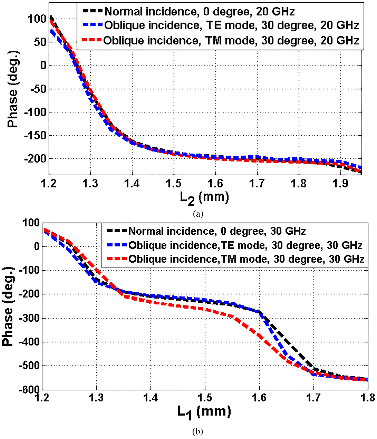
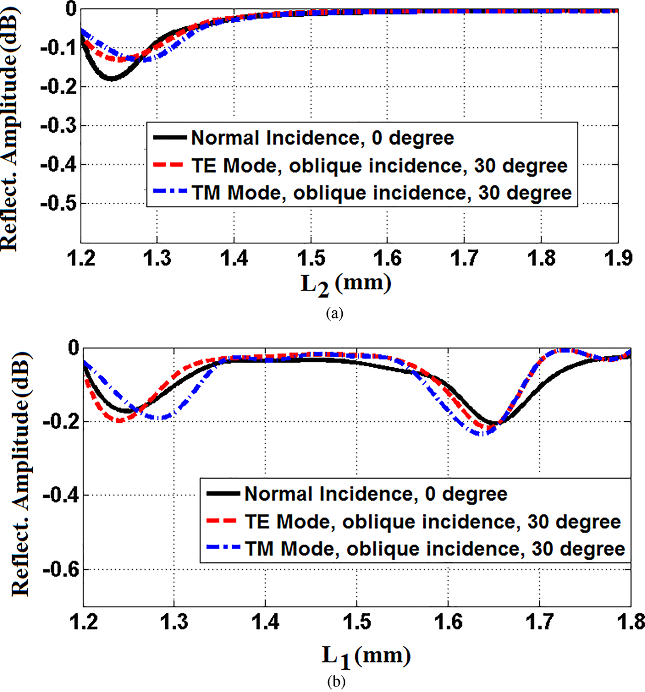
The phase shifts introduced by the designed unit cell at both operating frequencies (20 and 30 GHz) have been calculated assuming an infinite periodic array model [Reference Huang and Encinar1]. Figure 2(a) shows the reflection phase at 20 GHz under normal and oblique (θ = 30°, φ = 0°) incidences for both TM- and TE-polarized waves with respect to the length L 2, while Fig. 2(b) shows the reflection phase at 30 GHz under the same incidence conditions with respect to the length L 1. The results in Figs 2(a) and 2(b) illustrate that the phase response is quite linear and that more than 350° and 500° of phase range is achieved at 20 and 30 GHz, respectively. Note that the phase response at the two design frequencies can be controlled by only two parameters, L 1 and L 2. A two-dimensional interpolation method will be used to calculate the optimum values of L 1 and L 2 in each unit cell that provide the minimum phase error, as will be shown in the section “Design of the reflectarray antenna.” The amplitude of the cell reflection coefficient is shown in Figs 3(a) and 3(b) for 20 and 30 GHz, respectively. The maximum loss is about 0.18 dB at 20 GHz and 0.22 dB at 30 GHz.
Simulated phase of the cell reflection coefficient: (a) at 20 GHz (L 1 is fixed at 1.5 mm) and (b) at 30 GHz (L 2 is fixed at 1.5 mm).

Simulated magnitude of the cell reflection coefficient: (a) at 20 GHz (L 1 is fixed at 1.5 mm) and (b) at 30 GHz (L 2 is fixed at 1.5 mm).

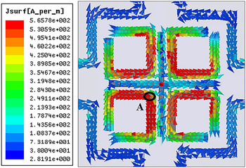
One of our ideas to design a new reflectarray antenna with a wide phase range is provided by using truncated rings electromagnetically coupled to the cross dipoles. Figure 4 shows the surface current distributions created from the HFSS computer model of the proposed resonant elements at 30 GHz, where red color shows the sections which have the largest concentration of surface current. As shown in Fig. 4, the proposed four truncated rings have the lowest values of surface current at the end corner of the rings, and the highest values at the central point of the rings (point A). When the total length of the truncated rings is around λ/2, a second resonance can be created. Therefore, the four truncated rings are able to provide a second resonance and a phase range larger than 500° at 30 GHz.
Surface current distributions on the reflectarray resonant elements at 30 GHz (L 1 = 1.65 mm).

Design of the reflectarray antenna
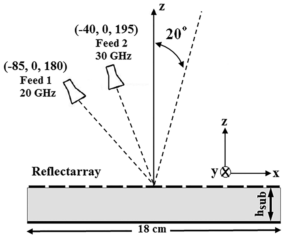
The proposed dual-band reflectarray antenna has been designed for operation in dual polarization at both operating frequencies (20 and 30 GHz). The reflectarray panel dimensions have been chosen as 18 × 18 cm2 (36 × 36 cells) to provide a gain close to 30 and 33 dBi at 20 and 30 GHz, respectively. To feed the proposed structure, two standard pyramidal horns from Narda (models 638 and V637) operating in K- and Ka-bands have been used [17]. The positions of the two feed-horns, which ensure a proper illumination on the reflectarray panel, are shown in Fig. 5. The feed locations are specified by the coordinates in mm of their phase centers with respect to the reflectarray geometrical center, being (−85, 0, 180) mm for the K-band horn (Feed 1) and (−40, 0, 195) mm for the Ka-band horn (Feed 2) (see Fig. 5). The radiation patterns of the feed-horns have been modeled as a cosq(θ) function, with q = 10.5 at 20 GHz for Feed 1 and q = 10.7 at 30 GHz for Feed 2, based on the approximate 3-dB beamwidth and gain of the horns provided by the manufacturer (Narda) [17]. Although the reflectarray cells show two-fold symmetry and they will operate in dual polarization (dual-linear or dual-circular), the horns used in the measurements of the reflectarray demonstrator are single linearly polarized. For this reason, TM polarization will be considered at 20 GHz and TE polarization at 30 GHz.
Schematic view of the reflectarray and the two separate feeds in the symmetry plane (Y = 0).

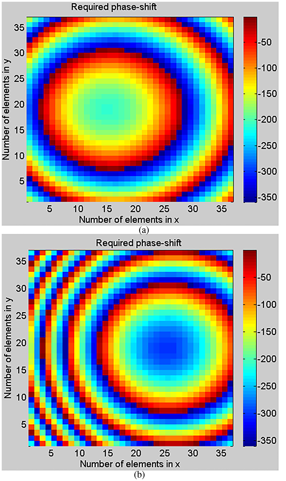
The proposed reflectarray antenna has been designed to radiate a focused beam in the XZ-plane (see Fig. 5), in the same direction for both frequency bands (θb = 20°, φb = 0°), in spite of the different positions of the horns used for each frequency. For that purpose, the reflectarray must introduce the phase shift distributions shown in Figs 6(a) and 6(b) at 20 and 30 GHz, respectively, in order to reflect the incident field radiated by the horns and produce a planar wave-front in the direction θb = 20°, φb = 0°. The phase shift required at each reflectarray element (ϕ) has been computed by means of the following expression (see [Reference Huang and Encinar1, ch. 3, p. 34]), which takes into account the path length from the feed to the reflectarray element:
 $$\phi \left( {x_i,y_i} \right) = k_0\; d_i-k_0\sin \theta _b\left( {x_i\cos \varphi _b + y_i\sin \varphi _b} \right)$$
In the above expression, k 0 is the propagation constant in vacuum, (xi, yi) are the coordinates of the i-element of the reflectarray, and di is the distance between the feed and the reflectarray i-element. This expression has been applied two times for each reflectarray element: one to obtain the required phase at 20 GHz (considering the position of Feed 1 and k 0 at 20 GHz) and the other to obtain the phase at 30 GHz (considering the position of Feed 2 and k 0 at 30 GHz). Note that θb = 20°, φb = 0° applies for the two frequencies. The resulting phase distributions shown in Fig. 6 have been used for the design of the reflectarray elements.
Phase shift distributions to be implemented on the reflectarray: (a) at 20 GHz and (b) at 30 GHz.

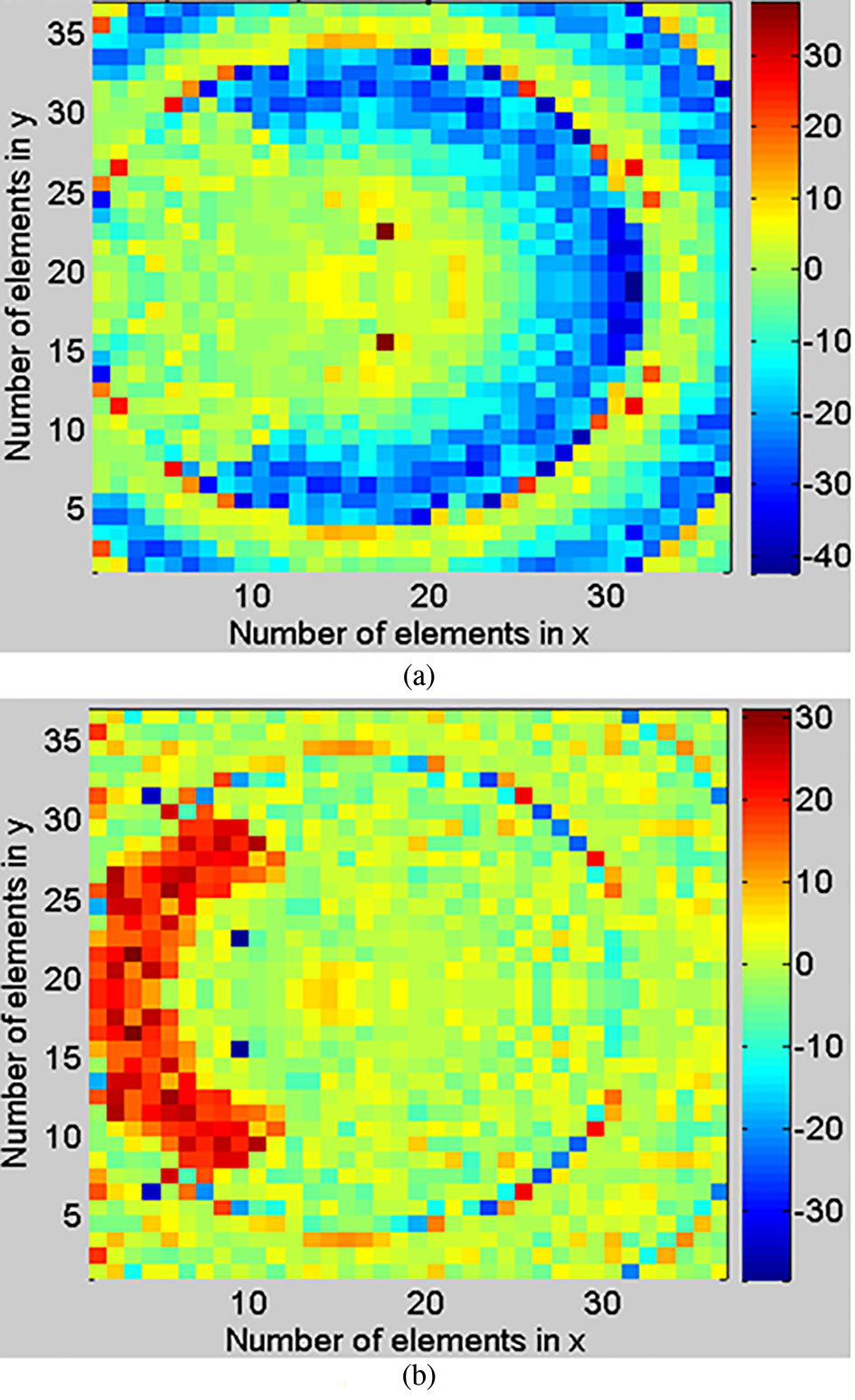
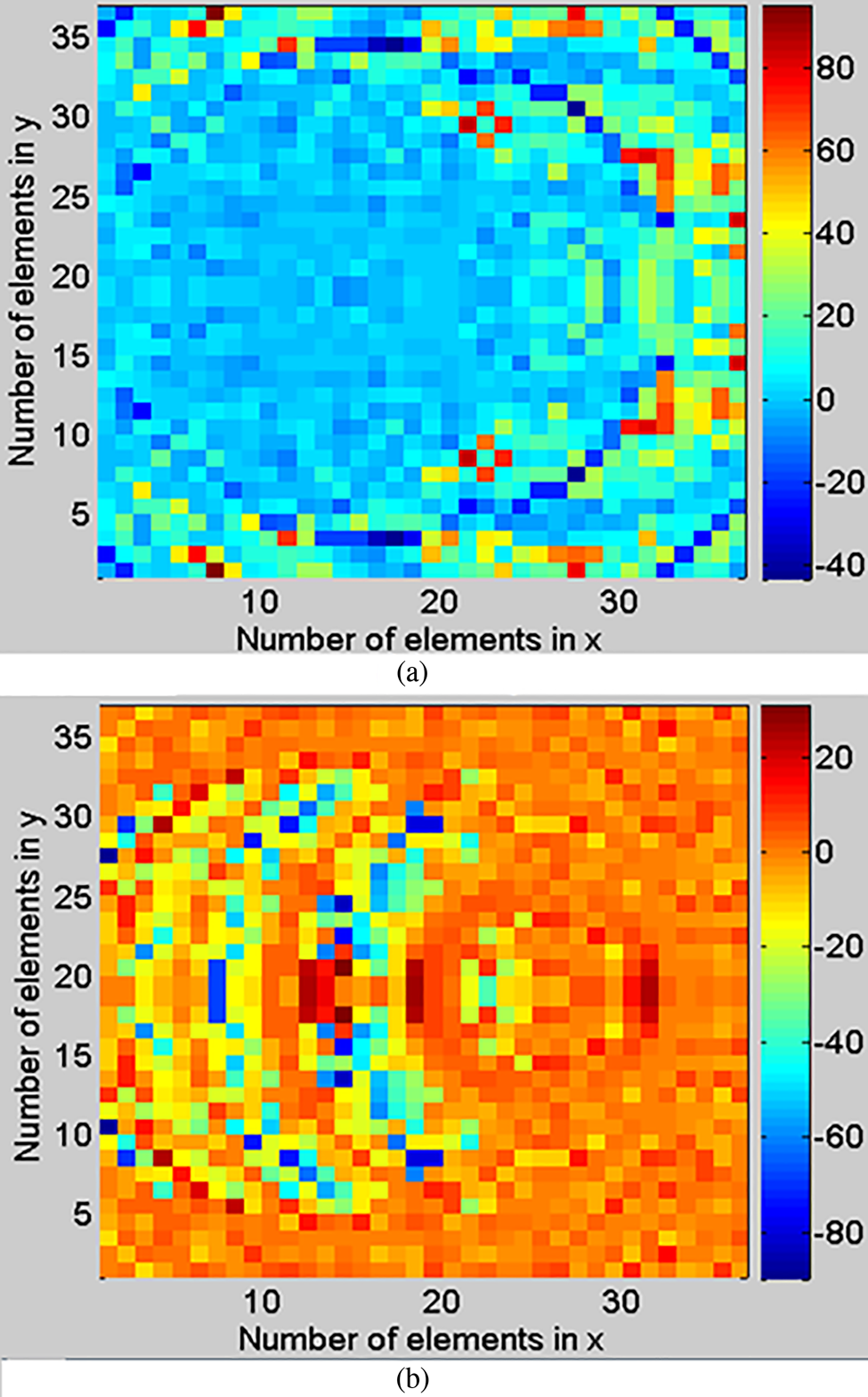
The values of the parameters L 1 and L 2 at each reflectarray cell that result in the minimum phase error at both operating frequencies are obtained by using a two dimensional interpolation method based on the previous simulations of the cell, in order to simultaneously match the required phases at 20 and 30 GHz. It has been found that our designed unit cell exhibits a low sensitivity with respect to the incidence angle (see Figs 2 and 3). Therefore, only two angles of incidence have been considered in the reflectarray antenna design: normal incidence simulations (θ = 0°) have been used when the incidence angle is θ < 20°, and oblique incidence simulations (θ = 30°) have been used when θ > 20°. As explained in the previous section, we have considered TM polarization for 20 GHz and TE polarization for 30 GHz. The resulting phase errors (difference between the ideal and simulated phases) have been calculated using the simulated phase response for 0° and 30° incidences, and the results are depicted in Fig. 7 for 20 GHz and in Fig. 8 for 30 GHz. These results illustrate that the approximate design method to calculate the values of L 1 and L 2 provides small and acceptable phase errors at the two design frequencies. The phase errors will increase when the frequency varies, reducing the bandwidth and gain of the designed reflectarray.
Phase errors at 20 GHz for the designed reflectarray antenna using the simulated results for: (a) normal incidence and (b) oblique incidence (θ = 30°, TM).

Phase errors at 30 GHz for the designed reflectarray antenna using the simulated results for: (a) normal incidence and (b) oblique incidence (θ = 30°, TE).

Experimental results
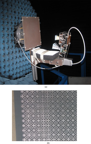
As shown in Fig. 9, the reflectarray antenna designed in the previous section has been fabricated and tested at the anechoic chamber of the Universidad Politécnica de Madrid (UPM). A structure with an aluminum holder that warranties the accurate position of the reflectarray and the feeds has been manufactured, which contains an arm with methacrylate supports to hold both feed horns. The printed elements of the designed reflectarray have been fabricated by conventional chemical photo-etching techniques. The dimensions of the printed elements were checked before the RF test of the fabricated reflectarray antenna, and this test indicated that there had been an averaged error of 25 μm in all the widths and lengths of the modified cross-shaped loops, dipoles, and truncated rings. The measurements of the reflectarray antenna were carried out in a compact antenna test range (CATR) system at the UPM. The reflectarray was placed in the quiet zone of the CATR system, where a large reflector of 4.5-m diameter was used to produce a planar wave-front for aperture illumination of the antenna under test. Due to the use of two pyramidal horns with single linear polarization, the radiated field was measured for TM polarization at 20 GHz and for TE polarization at 30 GHz. Then, the cuts of the radiation patterns of the fabricated reflectarray antenna in the principal planes (the XZ-plane—or elevation plane—and the orthogonal plane tilted 20° with respect to the Z-axis—or azimuth plane) were obtained.
(a) View of the fabricated Ka-band reflectarray antenna with the two feed-horns in the anechoic chamber. (b) Enlarged view of the reflectarray elements.

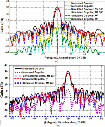
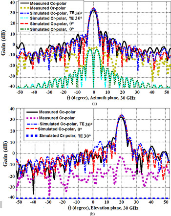
The comparison between the measured and simulated radiation patterns in the principal planes at the center operating frequencies (20 and 30 GHz) is illustrated in Figs 10 and 11. The radiation patterns show the amplitude (in dB) of the co- and cross-polar components for the TE and TM polarizations. The simulated radiation patterns have been computed from the EM simulations of the reflectarray cells assuming both normal (θ = 0°) and oblique (θ = 30°) incidences for the analysis. As can be seen in Figs 10 and 11, the direction of maximum radiation corresponds to an angle of 20° in elevation and 0° in azimuth, and it is the same for both operating frequencies. There is a quite good matching between measured and simulated results for the co-polar patterns in both the elevation and azimuth planes, and also for the cross-polar components in the azimuth plane. However, the measured gain is almost 1.5 dB lower than the simulated one. Note that this discrepancy is mainly produced by the losses in the dielectric, since we have used for the design the nominal value of loss tangent at 10 GHz provided by the manufacturer (tan δ = 0.0009), but later we have obtained a measured value of tan δ = 0.005 in the frequency band from 20 to 30 GHz (see [Reference Martinez-de-Rioja, Encinar, Barba, Florencio, Boix and Losada10]). Moreover, the cosq model is not accurate enough to characterize adequately the pyramidal horns used in the manufactured antenna, which results in higher side lobes. The radiated side lobes are reflected on the metallic supporting structure and lead to an antenna gain reduction. The measured gains of the reflectarray are 28.02 dBi at 20 GHz and 32.14 dBi at 30 GHz, which correspond to aperture efficiencies of 35.5 and 40.2% at 20 and 30 GHz, respectively.
Comparison of the measured and simulated radiation patterns for the manufactured reflectarray antenna at 20 GHz: (a) on the azimuth plane and (b) on the elevation plane.

Comparison of the measured and simulated radiation patterns for proposed reflectarray antenna at 30 GHz: (a) on the azimuth plane and (b) on the elevation plane.

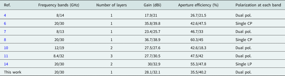
Table 1 shows a comparison between the proposed dual-frequency reflectarray antenna and other dual-frequency reflectarrays reported in the literature, with a special focus on those working at 20/30 GHz. As can be seen, the proposed reflectarray provides operation in dual polarization at both operating bands, it has a single layer and offers similar gain and aperture efficiency than other dual-band reflectarrays. In conclusion, it can be stated that the overall results are satisfactory and validate the proposed design concept for a single-layer dual-frequency reflectarray, showing a very good agreement between measurements and simulations at both frequency bands.
Comparison of the proposed reflectarray antenna with other dual-frequency reflectarrays existing in the literature

Conclusion
A novel dual-polarized, single-layer reflectarray antenna has been designed and manufactured for operation at two separate frequencies (20 and 30 GHz) with application to satellite communications in the Ka-band. The proposed reflectarray cells include a crossed dipole with four modified truncated rings and a cross-shaped loop of variable length that are etched on a conductor-backed substrate. The required phase shifts at the two operating frequencies are obtained by adjusting the geometrical parameters of the cells. An 18-cm reflectarray antenna demonstrator has been manufactured and tested, using two separate feeds to illuminate the reflectarray at 20 and 30 GHz. The measured patterns show a quite good agreement with the simulations, with measured gains of 32.14 dBi at 30 GHz and 28.02 dBi at 20 GHz.
Acknowledgements
This work has been supported by the Spanish Ministry of Economy and Competitiveness under the project TEC2016-75103-C2-1-R and by the European Regional Development Fund (ERDF).
 Mousa Abdollahvand received his M.Sc. degree in Communication Engineering from Shahed University, Tehran, in 2009, and he is currently pursuing his Ph.D. degree in Tarbiat Modares University, Iran. Also, he is a staff member of Mohaghegh Ardabili University, Iran. He was a research visitor at Universidad Politécnica de Madrid, Spain, in 2015. His main interests are UWB antennas, antenna arrays, reflectarray antennas, frequency selective surface, reconfigurable structures, equivalent circuit models, and numerical methods in electromagnetics.
 Keyvan Forooraghi received his M.Sc. degree in Electrical Engineering, the Licentiate of Technology degree from the Chalmers University of Technology, Gothenburg, Sweden, and his Ph.D. degree in Electrical Engineering from the Chalmers University of Technology in 1991. He was a Researcher with the Chalmers University of Technology from 1991 to 1992. In 1992, he joined the Department of Computer and Electrical Engineering, Tarbiat Modares University, where he is currently a Full Professor with the Communication Group. His research interests include electromagnetic theory and computational electromagnetic and antenna theory.
 Jose A. Encinar received his Electrical Engineer and Ph.D. degrees, both from Universidad Politécnica de Madrid (UPM), in 1979 and 1985, respectively. Since January 1980, he has been with the Applied Electromagnetics Group at UPM, as a Teaching and Research Assistant from 1980 to 1982, as an Assistant Professor from 1983 to 1986, and as Associate Professor from 1986 to 1991. Since 1991 he is a Full Professor of the Department of Signals, Systems and Radio Communications at UPM. He was a Visiting Professor with the Laboratory of Electromagnetics and Acoustics at Ecole Polytechnique Fédérale de Lausanne (EPFL), Switzerland, in 1996, and with the Institute of Electronics, Communication and Information Technology (ECIT), Queen's University Belfast, UK, in 2006 and 2011. His research interests include numerical techniques for the analysis of multi-layer periodic structures, design of frequency selective surfaces, printed arrays, and reflectarrays.
 Zahra Atlasbaf received her B.S. degree in Electrical Engineering from the University of Tehran, Tehran, Iran, in 1993, and her M.S. and Ph.D. degrees in Electrical Engineering from the University of Tarbiat Modares, Tehran, in 1996 and 2002, respectively. She is currently an Associate Professor with the Department of Electrical and Computer Engineering, Tarbiat Modares University. Her current research interests include numerical methods in electromagnetics, theory and applications of metamaterials, microwave and antenna design.
 Eduardo Martinez-de-Rioja received his Telecommunications Engineer and Ph.D. degrees, both from Universidad Politécnica de Madrid (UPM), Madrid, Spain, in 2014 and 2018, respectively. From 2015 to 2019, he was a Research Assistant with the Applied Electromagnetics Group at UPM. Since 2019 he is an Assistant Professor at the Department of Signal Theory and Communications and Telematic Systems and Computing, Universidad Rey Juan Carlos, Madrid, Spain. His research interests include the design of dual-frequency, dual-polarization, and multi-beam reflectarray antennas for satellite applications.