I. INTRODUCTION
Replacement of precious metal catalysts with less expensive materials of similar activity is of high priority. Because cobalt is substantially less expensive, due to its relative earth abundance, much research is being conducted to replace these precious metal catalysts with cobalt derivatives. Reference Zhang, Scott and Hanson1–Reference Seabold and Choi6 Cobalt oxides have been shown to be catalytic toward the oxygen evolution reaction (OER), Reference Liu, Koza and Switzer7–Reference Yeo and Bell10 and may be a useful substitute for the more expensive OER catalysts IrO2, RuO2, and PtO2. Reference Koza, He, Miller and Switzer11,Reference Trasatti12
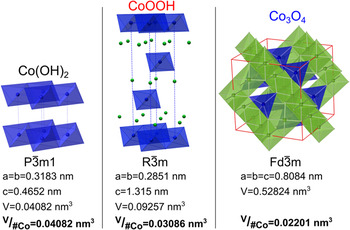
Catalysis depends on the exposed surface of a material. Thus, different crystal orientations, having varied composition and morphology, have different catalytic activities toward a reaction. Reference Zhou, Tian, Li, Broadwell and Sun13–Reference Su, Dou and Wang15 For spinel cobalt oxide the {111} family of planes shows the greatest activity toward the OER, Reference Su, Dou and Wang15–Reference Chen, Kronawitter and Koel17 as well as the oxygen reduction reaction. Reference Xie and Shen18,Reference Xiao, Kuang, Yang, Xiao, Wang and Guo19 We demonstrate a method to synthesize epitaxial Co3O4 with a [111] out-of-plane orientation as well as epitaxial Co(OH)2 and CoOOH with [0001] out-of-plane orientations. Synthesis begins with the electrodeposition of an epitaxial Co(OH)2 film. The Co(OH)2 film can then be converted through electrochemical oxidation to CoOOH or through thermal decomposition to Co3O4. Interestingly, while each cobalt material has a different crystal structure and a large decrease in volume per cobalt atom occurs as Co(OH)2 is converted into CoOOH and Co3O4, as shown in Fig. 1, epitaxy is still maintained. To maintain epitaxy the film develops mesopores and micro-fissures within the converted films. The increased porosity could be advantageous for catalysis due to the increased surface area. Reference Liu, Koza and Switzer7
Unit cells of cobalt hydroxide, oxyhydroxide, and oxide with space groups, cell parameters, and volume per cobalt atom.

II. EXPERIMENTAL
A. Electrodeposition of Co(OH)2
Co(OH)2 films were deposited from an aqueous solution of 10 mM [Co(en)3]Cl3 (where, en = ethylenediamine) in 2 M NaOH similar to the procedure described previously. Reference Koza, Hull, Liu and Switzer20 The electrodeposition experiments were performed at room temperature in a standard three-electrode setup using a Brinkmann PGSTAT 30 Autolab potentiostat (Metrohm Autolab B.V., Utrecht, The Netherlands). Au single crystals of [111], [100], and [110] orientations were used as working electrodes. A Pt mesh served as the counter electrode. The single-crystalline Au substrates were electropolished in an electrolyte composed of 1:1:2 v/v 38% HCl:ethylene glycol:ethanol at 55 °C at an anodic current density of 1.5 A/cm2. Reference Boonsalee, Gudavarthy, Bohannan and Switzer21 The Co(OH)2 films were deposited at −1 V versus Ag/AgCl/KClsat., which served as the reference electrode. Films were deposited to a charge density of 0.5C cm−2.
B. Film conversion
Co(OH)2 films were converted to CoOOH by anodic oxidation in 1 M NaOH at 95 °C. Reference Liu, Koza and Switzer7 The conversion was performed through cyclic voltammetry (CV) by scanning from the open circuit potential to 0.3 VAg/AgCl at a 10 mV/s scan rate for 20 cycles, similar to the procedure described previously. Reference Liu, Koza and Switzer7 Thermal decomposition of CoOOH films to Co3O4 was done by heating the films in a 300 °C oven in air for 1.5 h. Reference Liu, Koza and Switzer7
C. Characterization
The films were characterized using a high-resolution Philips X'Pert MRD X-ray diffractometer (XRD; FEI Company, Eindhoven, The Netherlands) with a
 ${\rm{Cu}}{{\rm{K}}_{{\alpha _1}}}$
radiation source (λ = 1.54056 Å). The morphology of the films was studied by scanning electron microscopy (SEM; Hitachi S-4700 FESEM, Hitachi Corp., Tokyo, Japan, and Helios Nanolab 600 FIB, FEI Company).
III. RESULTS
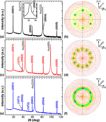
Cobalt hydroxide was electrochemically deposited onto Au single crystal substrates. Figure 2 shows XRD patterns for Co(OH)2 films deposited on Au single crystals of [111] (a), [100] (c), and [110] (e) orientations. Regardless of the substrate orientation, the films are highly textured, showing the {0001} peaks. As the substrate out-of-plane orientation does not affect the resulting out-of-plane order of the deposited film, the observed [0001] growth direction must be energetically favorable, as is also observed for electrodeposited zinc oxide.
Reference Liu, Vertegel, Bohannan, Sorenson and Switzer22
Since a strong preferred out-of-plane orientation was observed for the films, the in-plane orientation was probed to determine whether the films are epitaxial or fiber textured. We probed the in-plane orientations by measuring
 $\left( {10\bar 12} \right)$
pole figures. If the sample were epitaxial the resulting pole figure would have high intensity spots caused by a coordinated reflection from each crystal as each crystal is aligned. Whereas a sample having fiber texture would give a high intensity ring in the pole figure, because the crystals are rotated in a random fashion. Figure 2 shows
 $\left( {10\bar 12} \right)$
pole figures for Co(OH)2 films deposited on Au(111) (b), (100) (d), and (110) (f) substrates. Irrespective of the substrate orientation, the pole figures have a spot pattern having tilt angle (ψ) of 40°. This is in agreement with the angle between the (0001) and
 $\left( {10\bar 12} \right)$
planes (ψ = 40.17°). The spot patterns indicate epitaxial growth of Co(OH)2 films. The pole figure measured for the film deposited on Au(111) substrate shows 6-fold symmetry [Fig. 2(b)]. While a 3-fold symmetric spot pattern is expected due to the crystal symmetry of Co(OH)2, there are two equivalent in-plane orientations in which the crystals can grow on the Au(111) substrate. These two in-plane orientations are rotated 180° relative to each other which results in two sets of three spots, with each alternating spot coming from opposite orientations. Thus six spots are obtained, each rotated by 60°. We determined the epitaxial relationship on Au(111) as Co(OH)2(0001)
 $\left[ {01\bar 10} \right]$
∥Au(111)
 $\left\langle {2\bar 1\bar 1} \right\rangle$
. The
 $\left( {10\bar 12} \right)$
pole figure measured for the film deposited on Au(100) substrate has 12-fold symmetry with spots rotated by an angle of 30° [Fig. 2(d)]. Again this can be explained, because there are four equivalent in-plane orientations that Co(OH)2 can grow on the Au(100) substrate, each rotated by 90°. Thus four sets of three spots are observed in the pole figure, each set rotated by 90°. The epitaxial relationship for the film deposited on Au(100) substrate was determined to be Co(OH)2(0001)
 $\left[ {01\bar 10} \right]$
∥Au(100) 〈011〉. The pole figure for the film deposited on Au(110) substrate [Fig. 2(f)] shows six spots just as the Au(111) substrate. Again there are two equivalent in-plane orientations rotated by 180° which the Co(OH)2 can grow on the substrate. This is a result of the 2-fold symmetry of the Au(110) plane. While we observe six intense spots, there is also a low intensity ring indicative of some contribution of a fiber texture (random in-plane order of crystals). The epitaxial relationship for the film deposited on Au(110) substrate is Co(OH)2(0001)
 $\left[ {01\bar 10} \right]$
∥Au(110)〈001〉.
XRD patterns and pole figures of Co(OH)2 deposited on Au(111) (a and b), Au(100) (c and d), and Au(110) (e and f) single crystals.

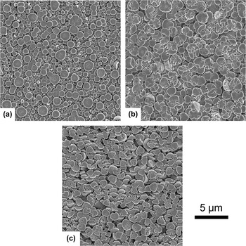
Figure 3 shows SEM plan view images of the Co(OH)2 films deposited on Au(111) (a), Au(100) (b), and Au(110) (c) substrates. The films all have a similar morphology. As already reported for the [0001] textured films deposited on Au coated glass substrate, Reference Liu, Koza and Switzer7 the films consist of conical grains having flat faces exposed. The majority of grains are oriented with the flat faces parallel to the substrate. However, the film deposited on Au(110) substrate has a number of cones which are tilted [Fig. 3(c)]. In all cases, the films consist of features with flat surfaces and nearly round microcones that do not show the expected faceting. This suggests that the microcones consist of smaller nanometer-scale crystallites that assemble into this microcone morphology. We note that the initial deposits of Co(OH)2 show faceted hexagonal nanograins in the atomic force microscope (image not shown).
Plan view SEM micrographs of Co(OH)2 films deposited on Au(111) (a), Au(100) (b), and Au(110) (c) single crystals.

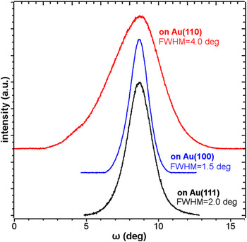
To probe the mosaic spread of the epitaxy we measured rocking curves at the (0001) Co(OH)2 peak (Fig. 4). The films deposited on Au(111) (black) and Au(100) (blue) show relatively sharp peaks of full width at half maximum (FWHM) of 2.0° and 1.5°, respectively. However, the film deposited on Au(110) substrate has a FWHM of 4.0° (red in Fig. 4), twice as broad as on the other substrates. This means that there is a larger mosaic spread for the film on Au(110) substrate, which is in agreement with the tilted cones observed by SEM [Fig. 3(c)].
X-ray rocking curves measured at (0001) peak for Co(OH)2 films deposited on Au(111) (black), Au(100) (blue), and Au(110) (red). The full width at half maximum (FWHM) are as indicated.

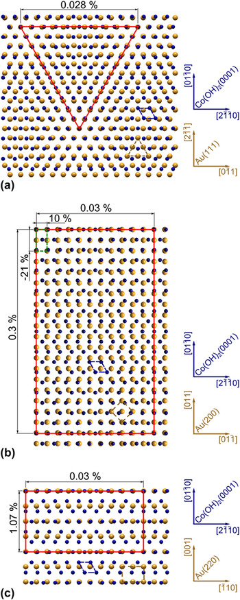
We modeled the Co(OH)2/Au interfaces for the different substrate orientations. Figure 5 shows the interface model of Co(OH)2(0001) on Au(111) (a), Au(100) (b), and Au(110) (c) oriented according to the epitaxial relationships determined from pole figures. A Moiré pattern in the interface model for Co(OH)2(0001) on Au(111) can be seen giving a coincident site lattice (CSL) in the shape of an equilateral triangle of 11 Co atoms along the
 $\left[ {11\bar 20} \right]$
,
 $\left[ {2\bar 1\bar 10} \right]$
, and
 $\left[ {\bar 1210} \right]$
directions. The CSL results in a lattice mismatch of only 0.028%. The CSL of Co(OH)2(0001) on Au(100) forms a rectangle having again 11 cobalt atoms on each side. The lattice mismatch for the CSL is 0.3% along the
 $\left[ {01\bar 10} \right]$
direction and 0.03% along the
 $\left[ {2\bar 1\bar 10} \right]$
direction. The smallest CSL is found for Co(OH)2(0001) on Au(110), however it had the largest mismatch. The CSL in this case also has a rectangular shape having 4 Co atoms along
 $\left[ {01\bar 10} \right]$
direction with a mismatch of 1.07% and 11 Co atoms along
 $\left[ {2\bar 1\bar 10} \right]$
direction with a mismatch of 0.03%. The lattice mismatch of 1.07% for Co(OH)2(0001) on Au(110), highest among other substrates, could be responsible for the increased mosaic spread observed in this system.
Interface models of Co(OH)2(0001) on Au(111) (a) Au(100) (b), and Au(110) (c). Only Co atoms are shown for Co(OH)2 as blue spheres. The Au atoms are shown as yellow spheres. Co(OH)2(0001) unit cell is indicated in blue, and Au unit cells are highlighted in yellow. The CSLs are drawn in red. Insets show the directions in Co(OH)2(0001) and Au planes.

As we previously reported, it is possible to oxidize Co(OH)2 films to either CoOOH or Co3O4 by electrochemical and thermal means. Reference Liu, Koza and Switzer7 It has also been shown that conversion of cobalt hydroxide to higher oxides does not always cause a change in morphology. Reference Cheng, Shereef, Gray and Wu23–Reference Tan, Gao, Yang, Luan, Dong, Jin, Yu, Qi, Feng and Wang25 Xu et al. report that conversion of β-Co(OH)2 to Co3O4 via thermal decomposition in air results in Co3O4 with morphologies dependent on the Co(OH)2 starting material. Reference Xu, Zhang, Wang and Liu26 They further reported a decrease in crystallite size and subsequent increase in porosity in the decomposed sample. This is not only observed in polycrystalline samples, but in single crystals as well. Lou et al. synthesized single crystal nano-needles of β-Co(OH)2, which remained single crystalline after decomposition to Co3O4, even upon development of mesopores. Reference Lou, Deng, Lee and Archer27
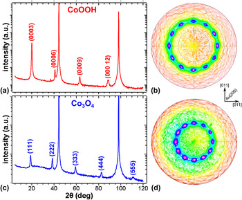
We hypothesized that if one started with epitaxial Co(OH)2 films, one could produce both epitaxial CoOOH and epitaxial Co3O4 films. We tested this hypothesis by oxidizing a Co(OH)2 film deposited on Au(100) single crystal substrate. The film was first oxidized electrochemically. The XRD pattern of the oxidized film shown in Fig. 6(a), is assigned to trigonal CoOOH with only {0001} reflections present. This once again shows the high level of out-of-plane order of the film upon oxidation. A slight broadening of the sample peaks is also observed, which could be due to a decrease in crystallite size. The CoOOH
 $\left( {01\bar 15} \right)$
pole figure is shown in Fig. 6(b). It has a spot pattern, indicating in-plane order in the film. The CoOOH
 $\left( {01\bar 15} \right)$
pole figure shows 12 spots separated by 30° at a ψ angle of 47° in agreement with the angle between (0001) and
 $\left( {01\bar 15} \right)$
planes of CoOOH (ψ = 46.81°). We have shown previously that the conversion starts at the film/electrolyte interface.
Reference Liu, Koza and Switzer7
Thus the four orientations of Co(OH)2 are maintained in the CoOOH film resulting in twelve spots just as in the pole figure for Co(OH)2 on Au(100) [Fig. 2(e)]. The epitaxial relationship is CoOOH(0001)
 $\left[ {01\bar 10} \right]$
∥Au(100)〈011〉. The CoOOH film was annealed in air at 300 °C. Decomposition through thermal means produced Co3O4, which displayed only reflections of the {111} planes in the XRD pattern [Fig. 6(c)]. This shows the conversion of trigonal CoOOH to the cubic spinel structure of Co3O4. Again peak broadening was observed, just as with the oxidation of Co(OH)2 to CoOOH. The Co3O4(220) pole showed a distinct 12 spot pattern with the spots separated by 30° at a ψ angle of 35° corresponding to the angle between (111) and (220) planes in the spinel structure of Co3O4 (ψ = 35.26°). Twelve spots are due to the combination of 3-fold symmetry of the Co3O4(111) plane with the 4-fold Au(100) substrate. The epitaxial relationship was determined as Co3O4(111)
 $\left[ {11\bar 2} \right]$
∥Au(100)〈001〉. This is the same epitaxial relationship we previously reported for the directly deposited epitaxial Co3O4 films on Au(100).
Reference Koza, He, Miller and Switzer11
XRD patterns and pole figures of CoOOH converted by anodic oxidation of Co(OH)2 (a and b) and Co3O4 thermally decomposed from CoOOH (c and d).

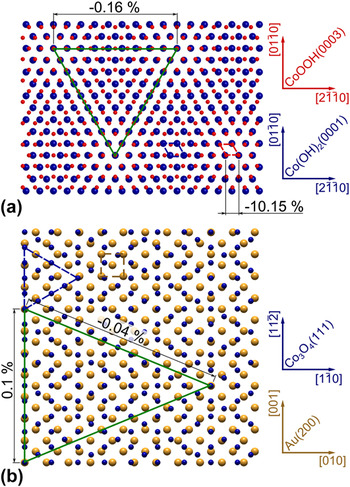
The interface models for the converted films are shown in Fig. 7. The CoOOH and Co(OH)2 both grow with the [0001] direction perpendicular to the substrate. Hence they have a hexagonal basal plane parallel to the surface, and therefore we can calculate the lattice mismatch of a single unit cell. The lattice mismatch for a single CoOOH(0001) unit cell overlaid on the Co(OH)2(0001) unit cell gives a mismatch of −10.15% [Fig. 7(a)]. However, if we expand the surface net a clear Moiré pattern is seen, giving a CSL in the shape of an equilateral triangle of 10 Co atoms along
 $\left[ {11\bar 20} \right]$
,
 $\left[ {2\bar 1\bar 10} \right]$
, and
 $\left[ {\bar 1210} \right]$
directions. This CSL reduces the mismatch to only −0.16%. The Co3O4(111) on Au(100) interface model is shown in Fig. 7(b). A triangular CSL is found with a mismatch of 0.1 and 0.04%.
(a) Interface model of CoOOH(0001) on Co(OH)2(0001). Small blue spheres stand for Co atoms on CoOOH(0001) plane and blue spheres represent Co atoms on the Co(OH)2(0001) plane. (b) Interface model of Co3O4(111) on Au(100). Only Co atoms are shown for Co3O4 as blue spheres. The Au atoms are shown as yellow spheres. CoOOH(0001) unit cell is shown with red dashed line. Co(OH)2(0001) and Co3O4(111) unit cells are indicated with blue dashed lines, and Au(100) unit cell is highlighted in yellow. The CSLs are drawn in green.

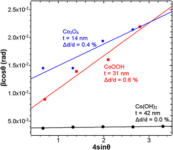
As previously mentioned, peak broadening was observed in the XRD patterns after each conversion, suggesting decreasing crystallite size. Using the Williamson–Hall analysis (Fig. 8) the lattice strain (Δd/d) and crystallite size (t) was calculated. Reference Williamson and Hall28 The Williamson–Hall equation:
 $${\beta _{hkl}}\cos \left( \theta \right) = {{K\lambda } \over t} + 4\left( {{{\Delta d} \over d}} \right)\sin \left( \theta \right)$$
relates the peak broadening
 $\left( {{\beta _{hkl}}} \right)$
to the strain in the crystal, which when graphed versus
 $4\;\sin \left( \theta \right)$
, gives a slope equal to the crystal strain and a Y-intercept which is a rearrangement of the Scherrer equation (where K is the dimensionless shape factor (0.94), λ is the wave length of the x-ray). Note that the x-ray measurements probe the size and strain of the entire film on the Au single-crystal substrates. As expected, the as-deposited Co(OH)2 films had little to no strain, with a Δd/d = 0.0%. The as-deposited film also had the largest crystallite size of 42 nm. The CoOOH films exhibited the greatest strain (the steepest slope in Fig. 8) with a Δd/d = 0.6% and a crystallite size of 31 nm. The Co3O4 film showed decreased strain of 0.4% compared to the CoOOH film. The crystallite size of the Co3O4 was the smallest with a size of 14 nm. The release of strain in Co3O4 is most likely observed due to the elevated temperature during decomposition (300 °C). While the temperature is well below the decomposition point of Co3O4 (895 °C),
Reference Haynes, Lide and Bruno29
it could be high enough to release some of the strain.
Williamson–Hall analysis of as-deposited Co(OH)2 film (black spheres), electrochemically oxidized to CoOOH (red squares), and Co3O4 (blue diamonds).

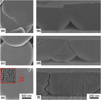
Figure 9 shows the plan view (a, c, and e) and cross-sectional (b, d, and f) SEM images of the film before and after each conversion step. The films after each step of the conversion retain the conical-like grain shape, as we previously reported for the textured films. Reference Liu, Koza and Switzer7 The as-deposited material shows no cracks on the surface of the cones [Fig. 9(a)] and no porosity in the bulk of the cones [Fig. 9(b)]. However, after electrochemical conversion to CoOOH both surface cracks [Fig. 9(c)] and porosity inside the cones [Fig. 9(d)] develop. The size and number of surface cracks [Fig. 9(e)] as well as porosity [Fig. 9(f)] continue to increase after thermal decomposition to Co3O4. In this case a significant surface roughening is also seen [inset of Fig. 9(e)]. This effect was reported for decomposition of single crystalline CoOOH nano-needles to Co3O4 nano-needles as well. Reference Lou, Deng, Lee and Archer27 The nano-needles retained their original geometry and were still single crystalline, but a nanoporosity developed, Reference Lou, Deng, Lee and Archer27 similar to the results we observed.
SEM images of the surface (left column) and cross-section (right column) of the as-deposited Co(OH)2 (a and b), after electrochemical conversion to CoOOH (c and d), and CoOOH oxidized to Co3O4 (e and f). The inset in (e) is the magnified surface area highlighted with the red square.

The nanoporosity can be explained based on the shrinkage of the film due to the structure changes. Comparing the crystal structure of Co(OH)2 to that of CoOOH and Co3O4 reveals that, upon conversion, the volume occupied per cobalt atom decreases (Fig. 1). Co(OH)2, which has a trigonal
 $P\bar 3m1$
space group changes to a space group of
 $R\bar 3m$
when oxidized to CoOOH. However, upon decomposition to Co3O4 the entire crystal system changes, adopting the cubic
 $Fd\bar 3m$
symmetry. This is accompanied by an almost 2-fold shrinkage of the unit cell volume calculated per Co atom. Experimentally this induces strain, increases porosity, and results in creation of micro-fissures through the crystallites. The formation of nanopores and cracks allows maintenance of the cone-like grain morphology despite the large film volume shrinkage. This is analogous to the results reported for the single-crystalline CoOOH nano-needles.
Reference Lou, Deng, Lee and Archer27
Both the increased strain and increased porosity could enhance the catalytic activity of the CoOOH.
IV. CONCLUSION
We have shown that epitaxial Co(OH)2 films can be electrodeposited on Au single crystals. Deposits grow in the [0001] out-of-plane direction independent of the substrate orientation. However, the in-plane orientation is determined by the gold crystal orientation. Films develop a cone-like microstructure and are uniform with very flat surfaces and negligible strain.
Co(OH)2 can be converted to CoOOH by electrochemical oxidation, which after conversion remains epitaxial with a [0001] out-of-plane orientation. The CoOOH film can be further converted to epitaxial Co3O4 with a [111] out-of-plane orientation by thermal decomposition in air. Williamson–Hall analysis revealed that after electrochemical oxidation of Co(OH)2 to CoOOH the strain in the film increases and the crystallite size decreases. Thermal decomposition of CoOOH to Co3O4 leads to a reduction of strain in the film and a further decrease in the crystallite size.
The film after each conversion step retains the micro-cone morphology despite the fact that the cell volume per cobalt atom is decreased nearly 2-fold after converting from Co(OH)2 to Co3O4. As a result the films develop increased porosity and micro-fissures.
This method allows for a simple fabrication of epitaxial catalysts with Co oxidation states of II, III, or a mixture of II and III, depending on the catalyst need. The converted films have the added benefit of increased surface area due to the inherent porosity caused by conversion. Thanks to the epitaxial growth, the catalytic activity of separate crystal planes toward different chemical reactions could be probed. One such reaction would be the OER, which is a critical reaction in realizing economical solar hydrogen production.
ACKNOWLEDGMENTS
This work was supported by the U.S. Department of Energy, Office of Basic Energy Sciences, Division of Materials Sciences and Engineering, under Grant No. DE-FG02-08ER46518.