I. INTRODUCTION
Intermetallic NiAl is considered as a candidate for future high temperature structural materials, due to its high melting point, low density, good thermal conductivity, and excellent oxidation resistance.Reference Noebe, Bowman and Nathal1 However, its poor high temperature strength and low fracture toughness limit its industry applications. Fortunately, the improvements in the room temperature fracture toughness of the NiAl alloy are achievable through the introduction of toughening phase, like the introduction of α-Cr, α-Mo, and α-Cr(Mo) phase is to form NiAl–Cr,Reference Johnson, Chen, Oliver, Noebe and Whittenberger2–Reference Misra and Gibala4 NiAl–Mo,Reference Misra and Gibala4–Reference Bei and George6 and NiAl–Cr(Mo)Reference Johnson, Chen, Oliver, Noebe and Whittenberger2,Reference Wang and Shen7–Reference Sheng, Zhang, Guo and Ye18 eutectic composites, respectively. Among the three alloys, the NiAl–Cr(Mo) eutectic composite is regarded as the most promising high temperature structural material since it possesses a better comprehensive property in comparison to NiAl–Cr and NiAl–Mo eutectic composites.Reference Johnson, Chen, Oliver, Noebe and Whittenberger2
As the high temperature structural material, the NiAl–Cr(Mo) eutectic composite should keep the microstructures stable when exposure to high temperatures for long times. That is, the microstructure of the composite does not degrade significantly at high temperatures. It is well-known that the microstructural degradation is driven by the minimization of total interfacial free energy per unit volume. The total interfacial free energy per unit volume (G V) is given by the following equationReference Gali, Bei and George26:
 $${G_{\rm{V}}} = {A_{\rm{V}}}\sum\limits_i {{\sigma _i}{f_i}} \quad ,$$
where A V is the total interfacial area per unit volume, σi is the interfacial energy per unit area of interface i, and f i is the relative area fraction. That is, the thermal stability can be increased by decreasing G V, which can be achieved by decreasing the total interfacial area per unit volume (A V). In the lamellar structure, the total interfacial area per unit volume (A V) can be decreased with increasing the average interlamellar spacing. That is, the smaller interlamellar spacing may induce the degradation of the lamellar structure at high temperature. In previous investigation, the lamellar structure almost has no significant change after heat treatment at 1027 °C/500 hReference Chen, Johnson, Noebe and Oliver13 or 1100 °C/100 h.Reference Yang, Jeng, Bain and Amato14 Recently, our recent investigationReference Wang, Zhang, Shen, Zhang, Xu, Ge and Fu11 found that the cellular lamellar structure of the NiAl–Cr(Mo) eutectic composite becomes not stable, and the coarsening and local dissolution even cylinderization of lamellae occur at 1150 °C (≈0.8T m). It is deduced that the degradation of the lamellar structure should stem from the smaller interlamellar spacing “0.52 μm” (the corresponding withdrawal rate is 160 μm/s during directional solidification). Usually, the interlamellar spacing could increase with decreasing the withdrawal rate during directional solidification. Maybe, we decrease the withdrawal rate from 160 μm/s to slower values and obtain the thicker lamella to improve the thermal stability. During directional solidification, a planar (well-aligned) eutectic lamellar structure could be obtained at lower withdrawal rates, and the well-aligned lamellar structure may provide a significant property. Thus, we attempt to investigate the evolution of the NiAl–Cr(Mo) planar eutectic lamellar structure during high temperature treatment in this paper.
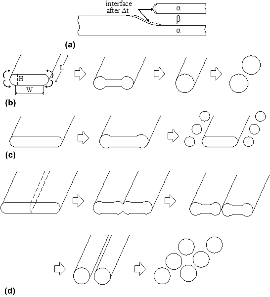
In addition, for lamellar structures, the lamellar geometry is inherently stable with respect to thickness perturbations along the length of the lamellas.Reference Lin and Courtney19 However, many researchers have reported that during high temperature treatment, the lamellar structures undergo coarsening and shape degradation after high temperature treatment in Al–CuAl2,Reference Graham and Kraft20 Pb–Sn,Reference Lin and Courtney19,Reference Eady and Winegard21,Reference Lin, Courtney and Ralls22 Sn–Cd,Reference Racek and Lesoult23 Ni–W,Reference Kampe, Courtney and Leng24,Reference Courtney and Kampe25 Cr–Cr3SiReference Gali, Bei and George26 eutectic alloys, Co–Si eutectoid alloy,Reference Livingston and Cahn27 and TiAl alloy.Reference Sharma, Ramanujan and Tiwari28 These instabilities occur due to the presence of structural defects, such as lamellar terminations, grain (colony) boundaries, and sub-boundaries. Usually, the coarsening of the lamellar structure occurs by a continuous mode or a discontinuous mode, and the two modes are closely related to the presence of structural defects. Previous investigations reported that the continuous coarsening usually occurs in the lamellar eutectic alloys.Reference Lin and Courtney19–Reference Gali, Bei and George26 Thus, we introduce four major continuous coarsening mechanismsReference Lin and Courtney19,Reference Graham and Kraft20,Reference Kampe, Courtney and Leng24,Reference Courtney and Kampe25,Reference Sharma, Ramanujan and Tiwari28 : (i) Termination migration. Coarsening by termination migration is one of the most common instability mechanisms. Due to the presence of termination curvature, a chemical potential gradient exists between the termination and the adjacent lamella. Thus, atoms diffuse from the termination to the adjacent lamella, resulting in the recession of termination and the thickening of adjacent lamella, as shown in Fig. 1(a). (ii) Cylinderization. The cylinderization mechanism usually occurs when the lamellar cross-sectional aspect ratio (W/H) is small in a finite lamella with termination curvature. Due to the termination curvature difference, the capillary forces drive the atom migration from the termination to the adjacent flat surface, thus inducing the transformation of termination shape and finally resulting in the formation of cylinder, as illustrated in Fig. 1(b). Furthermore, the cylinder may decompose into a row of spheres due to the Rayleigh instability process. (iii) Edge spheroidization. The edge spheroidization usually occurs when the lamellar cross-sectional aspect ratio (W/H) is large in a finite lamella with termination curvature. As before, due to the termination curvature difference, the transformation of termination shape occurs and associates with the formation of a ridge (considered as “partial” cylinder), as displayed in Fig. 1(c). The ridge is susceptible to the development of stable longitudinal perturbations, and the succession of events subsequent to ridge formation depends on the lamella cross-sectional aspect ratio. When the lamellar cross-sectional aspect ratio (W/H) is large, extensive edge recession causes the ridge to grow in girth and also provides time for the development and growth of perturbations along the ridge length, thus resulting in the decomposition of ridge into a row of spheres. (iv) Boundary splitting. Boundary splitting is a consequence of the presence of through thickness sub-boundaries which arise either due to the recrystallization of the deformed lamellar structure or phase transformation processes. At a high temperature, a groove develops along the line of intersection with the local equilibrium, and it is bordered by two ridges. The curvature of the ridges promotes a transport of the lamella material away from the groove, thus deepening the groove and splitting the lamella. Even, the cylinderization mechanism also occurs when the cross-sectional aspect ratio (W/H) of split lamella is small, and correspondingly the spheroidization also occurs due to the Rayleigh instability process (similar to ii mechanism). In this paper, we also discuss the instable mechanisms of NiAl–28Cr–6Mo eutectic lamellar structures.
Instability mechanisms in lamellar structuresReference Lin and Courtney19,Reference Graham and Kraft20,Reference Kampe, Courtney and Leng24,Reference Courtney and Kampe25,Reference Sharma, Ramanujan and Tiwari28 : (a) Termination migration, (b) direct cylinderization, (c) edge spheroidization, and (d) boundary splitting.

II. EXPERIMENTS
The composition of the tested alloy is Ni–33Al–28Cr–6Mo (at.%). The ingots were prepared by a vacuum induction melting. The Ф 7 mm rods were cut from the ingots by wire electro-discharged machine and placed in the high purity alumina crucible with 7.1 mm in inner diameter for directional solidification in the Bridgeman apparatus with induction heating. The temperature in the specimen was measured with 0.5 mm diameter insulated W–Re thermocouples inserted into the dual-hole alumina fixed within the sample. Two W–Re thermocouples were connected to the measurement unit which consists of data-logger and computer. The molten metal temperature is at 1655 ± 10 °C. The temperature gradient in the solid–liquid interface frontier (G L = ΔT/ΔX) was determined by the values of ΔT and ΔX and is ∼250 K/cm. The specimens were pulled down at the withdrawal rates (V) of 2.5, 4.5, and 7.5 μm/s. The pulling length of the directional solidification specimen was 60 mm. At the end of the experiment, the crucible was quickly dropped into the liquid Ga–In–Sn alloy to retain solid–liquid interface morphologies.
The directionally solidified specimens were cut along the longitudinal and transverse directions, and the transversely cut position is 5 mm below the solid–liquid (quenched) interface. It is respected that the NiAl–Cr(Mo) eutectic composite can be applied at 0.8T m (1150 °C) in future. Thus, the part of specimens were heat-treated for various times (1, 10, 50, 100, 200, and 400 h) at 1150 °C (≈0.8T m) in air. The sections were mechanically polished and then etched with a solution of 80% HCl + 20% HNO3 by volume. The microstructures were observed by using a confocal laser scanning microscope (CLSM; LEXT OLS4000, Olympus Corporation, Tokyo, Japan; standard optical microscopy) and a scanning electron microscope (SEM; JSM-6700F, JEOL, Tokyo, Japan). The eutectic interlamellar spacing was measured by Digimizer 6.0 metallurgical analysis software (MedCalc Software, Ostend, Belgium).
III. RESULTS AND DISCUSSION
A. Microstructure evolution of cast directionally solidified alloy
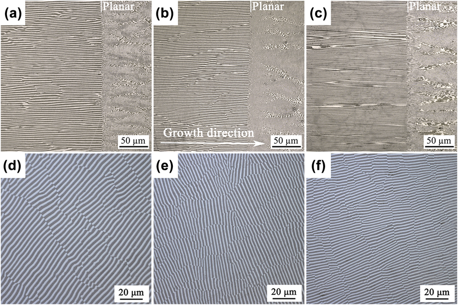
The longitudinal solid–liquid interface morphologies and transverse microstructures of NiAl–Cr(Mo) eutectic composites at different withdrawal rates are shown in Fig. 2. The straight solid–liquid interface morphologies are observed at 2.5, 4.5, and 7.5 μm/s, as shown in Figs. 2(a)–2(c), respectively. This indicates that the solid–liquid interface should have been stable and therefore planar during the directional solidification process. Previous investigation shows that the solid–liquid interface morphology depends on the temperature gradient (G L) at interface frontier and the withdrawal rate (V). Generally, the higher the value of G L/V, the smaller the constitutional supercooling, and correspondingly a stable planar interface is easily obtained. In the present experiment, the stable planar interface at the withdrawal rates of ≤7.5 μm/s shows that the constitutional supercooling at the interface frontier is small. It is deduced that the solid–liquid interface is stable and planar for NiAl–28Cr–6Mo eutectic composites when the value of G L/V is higher than 3.33 × 10⁵ K/(s cm2) (G L ∼ 250 K/cm). Figures 2(d)–2(f) show the corresponding transverse microstructures at 2.5, 4.5, and 7.5 μm/s, respectively. The result shows that the well-aligned planar eutectic lamellar structure can be obtained, and the eutectic lamellar structures consist of black NiAl phase and gray white Cr(Mo) phase. The average interlamellar spacing decreases from 3.70 μm at 2.5 μm/s to 2.4 μm at 4.5 μm/s, and to 1.95 μm at 7.5 μm/s.
Optical images of solid–liquid interface morphologies and transverse microstructures of NiAl–Cr(Mo) eutectic composites at (a and d) 2.5 μm/s, (b and e) 4.5 μm/s, and (c and f) 7.5 μm/s.

B. Microstructure evolution at 1150 °C
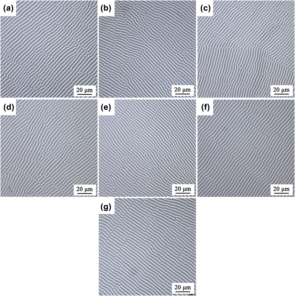
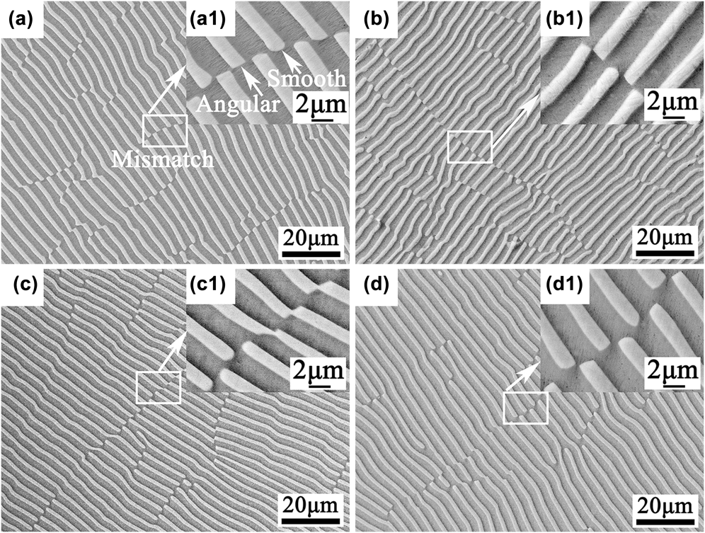
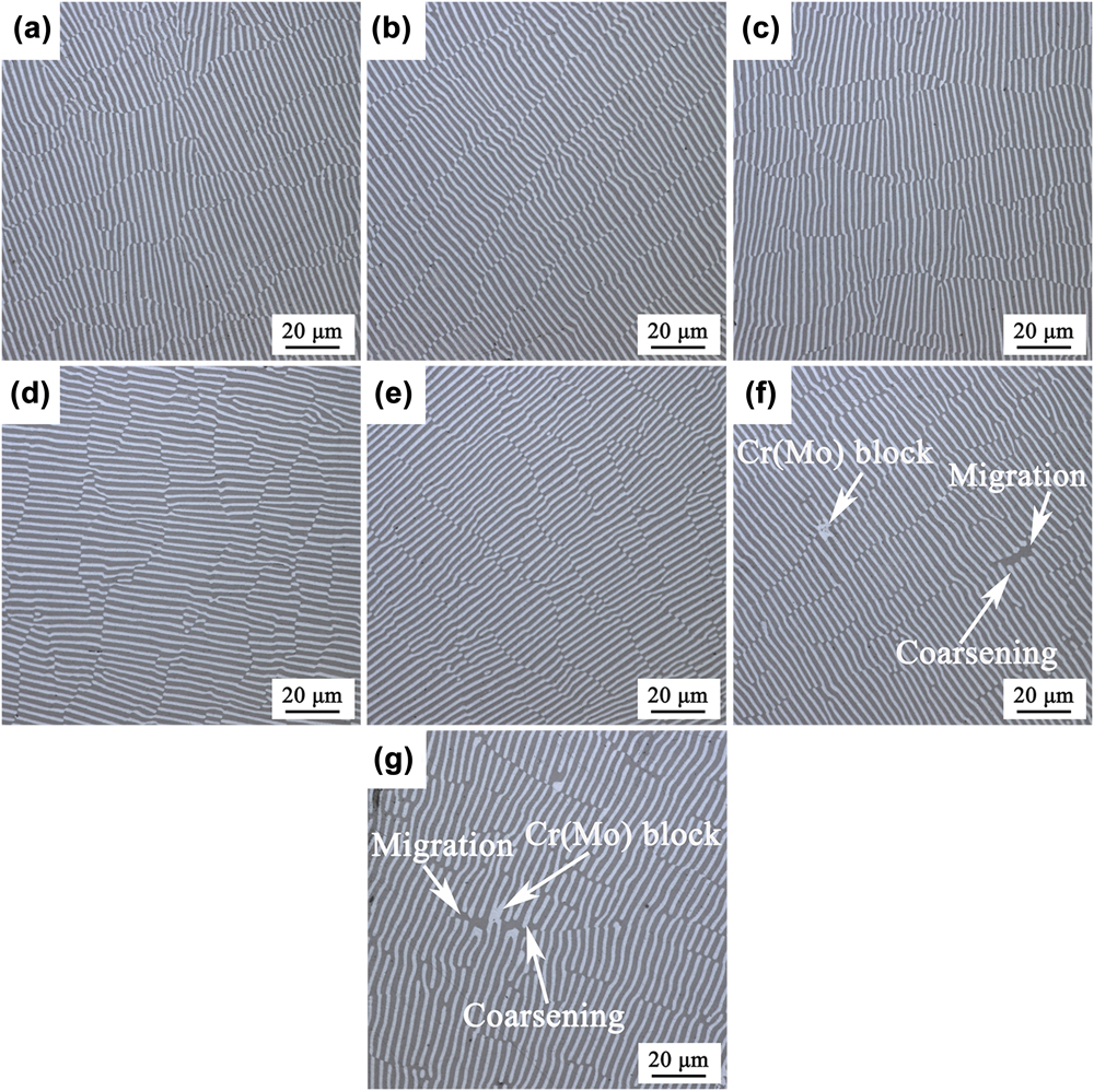
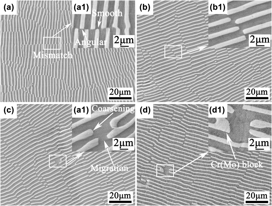
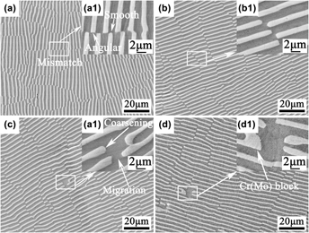
Figure 3 shows the optical images of transverse microstructures of NiAl–Cr(Mo) eutectic composites at 2.5 μm/s and various treatment times (0–400 h). From the optical observations, it seems that the lamellar structures have no significant change after high temperature treatment, as displayed in Figs. 3(a)–3(g). Meanwhile, the lamellar structures before and after high temperature treatment are closely examined by SEM (For simplicity, a part of SEM images are given in the following). Mismatches exist extensively in the as-DS alloy, and the morphologies of Cr(Mo) lamellar terminations (gray white) in the mismatch zone are angular or smooth (arc-like), as shown in Figs. 4(a) and 4(a1). After the high temperature treatment at various times, it can be seen from Figs. 4(b)–4(d) (lowly magnified image) that the observed result is almost similar to that of optical observation, namely no major changes occur in the lamellar structure. If the careful observation is done (see the highly magnified image), it seems that a little migration of Cr(Mo) lamellar termination occurs at times of up to 400 h, as shown in Fig. 4(d1). Moreover, no obvious coarsening occurs in this case. Abstractly speaking, the lamellar structure is almost stable at 2.5 μm/s.
Optical images of transverse microstructures of NiAl–Cr(Mo) eutectic composites at 2.5 μm/s and various treatment times [(a) 0 h, (b) 1 h, (c) 10 h, (d) 50 h, (e) 100 h, (f) 200 h, and (g) 400 h].

SEM images of transverse microstructures of NiAl–Cr(Mo) eutectic composites at 2.5 μm/s and various treatment times [(a and a1) 0 h, (b and b1) 10 h, (c and c1) 100 h, and (d and d1) 400 h].

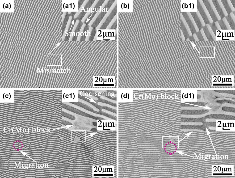
Figure 5 shows the optical microstructures of NiAl–Cr(Mo) eutectic composites at 4.5 μm/s and various treatment times (0–400 h). No major changes in eutectic morphology are observed after high temperature treatment at 100 h, as shown in Figs. 5(a)–5(e). With increasing the time to 200 h or 400 h, the coarsened and small blocky Cr(Mo) phases are observed in the localized zones, and correspondingly the migration is observed, as shown in Figs. 5(f) and 5(g). In fact, the small blocky Cr(Mo) phase is also a style of coarsening. To more clearly observe the microstructures, we have also done a SEM analysis. Similarly, it can be seen from the SEM image that the angular or smooth terminations are observed in the as-DS alloy, as shown in Fig. 6(a1). Moreover, the SEM images give more clear illustrations about the coarsening and migration of Cr(Mo) lamellar termination and the blocky Cr(Mo) phase. These observations indicate that the lamellar structure at 4.5 μm/s is relatively instable at 1150 °C compared to that at 2.5 μm/s.
Optical images of transverse microstructures of NiAl–Cr(Mo) eutectic composites at 4.5 μm/s and various treatment times [(a) 0 h, (b) 1 h, (c) 10 h, (d) 50 h, (e) 100 h, (f) 200 h, and (g) 400 h].

SEM images of transverse microstructures of NiAl–Cr(Mo) eutectic composites at 4.5 μm/s and various treatment times [(a and a1) 0 h, (b and b1) 10 h, (c and c1) 200 h, and (d and d1) 400 h].

Figure 7 shows the optical microstructures of NiAl–Cr(Mo) eutectic composites at 7.5 μm/s and various treatment times (0–400 h). The optical observation indicates that the microstructures have no significant change after high temperature treatment in short time (100 h), as shown in Figs. 7(a)–7(e). However, after 200 h, the small blocky Cr(Mo) phase forms in the localized zone, as displayed in Figs. 7(f) and 7(g). In addition, we also have done a close examination by SEM. Similarly, the morphologies of lamellar terminations have two forms, like angular or smooth, as shown in Fig. 8(a1). From the SEM images, besides the coarsening of termination and the blocky Cr(Mo) phase, the migration of termination are commonly observed, as illustrated in Figs. 8(c), 8(c1), 8(d), and 8(d1). These observations indicate that the lamellar structure at 7.5 μm/s is also instable at 1150 °C. According to the above observations, the lamellar structures undergo a change from relatively stable to instable status when the withdrawal rate increases from 2.5–7.5 μm/s. In addition, the interlamellar spacing after high temperature treatment is measured. Although the coarsening and migration of lamellae at the local region occur, on the whole, the interlamellar spacing has no significant change, as shown in Figs. 4, 6, and 8.
Optical images of transverse microstructures of NiAl–Cr(Mo) eutectic composites at 7.5 μm/s and various treatment times [(a) 0 h, (b) 1 h, (c) 10 h, (d) 50 h, (e) 100 h, (f) 200 h, and (g) 400 h].

SEM images of transverse microstructures of NiAl–Cr(Mo) eutectic composites at 7.5 μm/s and various treatment times [(a and a1) 0 h, (b and b1) 10 h, (c and c1) 200 h, and (d and d1) 400 h].

C. Instability mechanism of the lamellar structure
Despite the inherent stability of lamellar structures, size coarsening and shape degradation are still observed, and the relevant continuous coarsening mechanisms [like cylinderization, edge spheroidization, boundary splitting (see Sec. I)] and discontinuous coarsening mechanisms are discussed in previous investigations.Reference Lin and Courtney19,Reference Graham and Kraft20,Reference Kampe, Courtney and Leng24,Reference Courtney and Kampe25,Reference Sharma, Ramanujan and Tiwari28 The degradation of the lamellar structure is closely related to the presence of structural defects in the as-DS alloy, like termination and grain (colony) boundary. In the present investigation, the experimental observation shows that there exist the massive lamellar terminations in the as-DS alloy. The lamellar termination may induce the degradation of the lamellar structure, like the coarsening and migration of termination and the formation of the blocky Cr(Mo) phase. The relevant mechanisms are discussed as follows. In addition, there are no indications of discontinuous coarsening occurring in the present alloy since the discontinuous coarsening is only a result of the migration of grain boundaries into an adjacent grain. The discontinuous coarsening usually initiates at the lamellar colony boundaries. Under the influence of capillary forces and a chemical driving force arising from nonequilibrium volume fractions of various phases, the colony boundaries migrate and leave behind a coarser lamellar structure with an increased interlamellar spacing.Reference Sharma, Ramanujan and Tiwari28
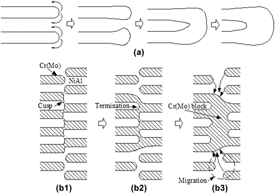
The morphologies of terminations are angular or smooth in the as-DS alloy [see Figs. 4(a1), 6(a1), and 8(a1)]. Compared to the angular termination, the smooth (arc-like) termination has a significant curvature. Evidently, the curvatures of smooth termination and adjacent flat surface are different. The capillary force due to the curvature difference promotes the mass transfer from the termination to the adjacent flat surface,Reference Kampe, Courtney and Leng24 thus leading to the coarsening of termination and the formation of ridges, as schematically shown in Fig. 9(a). The ridges grow due to further mass transport, thus resulting in the further coarsening. When the coarsening reaches to a certain degree, the adjacently coarsened terminations begin to assemble, thus resulting in the formation of the blocky Cr(Mo) phase, as schematically shown in Fig. 9(a). The styled blocky Cr(Mo) phase could be observed at 4.5 μm/s [Figs. 5(g) and 6(d)] and 7.5 μm/s [Fig. 7(g)].
(a) Schematic of the coarsening mechanism of termination and formation mechanism of the small blocky Cr(Mo) phase; (b1–b3) Schematic of formation and coarsening mechanisms of the blocky Cr(Mo) phase [(b1) mode of the as-DS microstructure with cusp, (b2) splitting of NiAl lamella, connection of neighbouring Cr(Mo) phases, and formation of NiAl termination, and (b3) formation and coarsening of the blocky Cr(Mo) phase and migration of termination].

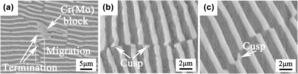
Moreover, another styled blocky Cr(Mo) phase is also observed at 4.5 μm/s [Fig. 5(f)] and 7.5 μm/s [Figs. 7(f), 8(c), and 8(d)]. Here, we take the typical microstructure at 7.5 μm/s as an example to explain the possible reason for the formation of the styled blocky Cr(Mo) phase, as shown in Fig. 10. It can be seen from Fig. 10(a) that the migrations of terminations occur near the blocky Cr(Mo) phase, and these terminations have no significant coarsening. It is deduced that the material of the blocky Cr(Mo) phase is derived from the adjacent terminations by diffusion. To further understand the instability mechanism, we have done the careful examination of the as-DS microstructure at 7.5 μm/s. It is found that besides the mismatch, another defect [like the cusp of Cr(Mo) phase] and the corresponding groove in the NiAl phase are observed, as displayed in Figs. 10(b) and 10(c). The formation of the blocky Cr(Mo) phase may be related to the existence of cusp of the Cr(Mo) phase. First, the existence of cusp of the Cr(Mo) phase may result in the lamellar splitting of the NiAl lamella, which is similar to that in the Cr–Cr3Si eutectic alloy.Reference Gali, Bei and George26 Splitting of NiAl lamella occurs when the curvature at a point in the cusp is higher compared to regions away from it, causing the groove to deepen due to material transport and the connection of neighbouring Cr(Mo) phases, thus resulting in the formation of NiAl lamellar termination with curvature, as shown in Fig. 9(b2). Once the termination with curvature is formed, subsequently the migration of termination occur by capillary force in the high temperature treatment process, thus resulting in the formation of the blocky Cr(Mo) phase, as displayed in Fig. 9(b3). Meanwhile, the migrations of Cr(Mo) lamellar terminations with curvature may occur by capillary force, and thus the materials compensate each other by material transport. That is, the material of the blocky Cr(Mo) phase (a style of coarsening) is derived from the dissolution (migration) of Cr(Mo) lamellar termination, which is the classical coarsening mechanism [see Fig. 1(a)] by termination migration. This may be responsible for the formation of the blocky Cr(Mo) phase. Therefore, the formation mechanism of the large blocky Cr(Mo) phase is originated from the lamellar splitting of the NiAl lamella due to the existence of cusp of the Cr(Mo) phase, and the needed materials during the growth stem from the neighbouring Cr(Mo) phases. However, the formation mechanism of the small blocky Cr(Mo) phase mentioned in the above paragraph is attributed to the capillary force due to the curvature difference, and the needed materials during the growth stem from itself.
Microstructure after high temperature treatment of 400 h (a) and as-DS microstructure (b and c) of the alloy at 7.5 μm/s.

From the above observation and discussion, it is not difficult to find that the thermal stability of planar eutectic lamellar structures begins to become poor with increasing the withdrawal rate (decreasing the interlamellar spacing). The theory with regard to thermal stability of the lamellar structure has been mentioned in Sec. I. Generally, the driving force of microstructural instability is the minimization of total interfacial free energy per unit volume (G V), and the total interfacial free energy per unit volume (G V) depends on the total interfacial area per unit volume (A V). The total interfacial area per unit volume (A V) depends on the interlamellar spacing (λ) for the lamellar structure. Previous investigation reported that A Vλ is a constant in a perfect lamellar structure.Reference Graham and Kraft20 That is, it keeps an inversely proportional relationship between A V and λ, and correspondingly it also keeps an inversely proportional relationship between G V and λ. Therefore, the total interfacial free energy per unit volume (G V) increases with decreasing the interlamellar spacing (λ), and thus resulting in microstructure degradation. In addition, a small interlamellar spacing can effectively reduce the diffusion distance of atoms between two phases, thus promoting the diffusion of atoms between two phases. Therefore, the thermal stability of the lamellar structure becomes poor with decreasing the interlamellar spacing. Correspondingly, the coarsening and migration of termination and the blocky phase emerge at a smaller interlamellar spacing [≤2.4 μm (4.5 μm/s)] in the present investigation. Compared to the recent investigationReference Wang, Zhang, Shen, Zhang, Xu, Ge and Fu11,Reference Wang, Shen, Zhang, Zhang, Guo, Ge, Gao and Fu29 that a deteriorative degradation occur in the thinner lamellar structure [0.52 μm (160 μm/s)], the lamellar structure is slightly instable at 4.5 and 7.5 μm/s in the present investigation. The similar degradation also occurs in the NiAl–Cr and NiAl–Mo fibrous eutectic alloys, such as coarsening, migration even spheroidization of α-Cr and α-Mo fibers.Reference Walter and Cline30,Reference Gali, Bei and George31
IV. CONCLUSION
The microstructure evolution of the directionally solidified NiAl–Cr(Mo) planar eutectic lamellar structure has been investigated at 1150 °C/(0–400) h, which could provide some information to future industrial application. The obtained results are summarized as follows:
(1) The lamellar structure is almost stable at times of up to 400 h (1150 °C) and at a lower withdrawal rate (2.5 μm/s).
(2) The lamellar structure is slightly instable when the withdrawal rate increases further, like the coarsening and migration of termination occur and the blocky Cr(Mo) phase forms at 200 h. The decrease of microstructural stability is attributed to the driving force of larger total interfacial free energy per unit volume at higher withdrawal rates.
(3) The curvature difference between the termination and the adjacent flat surface could be responsible for the coarsening and migration of termination. The formation of the blocky Cr(Mo) phase is related to the existence of cusp of the Cr(Mo) phase.
ACKNOWLEDGMENTS
The work is supported by the National Natural Science Foundation of China (51501147, 51601144, and 51674196); Natural Science Basic Research Plan in Shaanxi Province of China (2016JQ5013); the fund of the State Key Laboratory of Solidification Processing in NWPU (SKLSP201509); and the fund of undergraduate innovation and entrepreneurship project of Xi’an University of Technology.