Introduction
Electron microscopy (EM) has been actively used in elucidating structures of polymeric materials. Microscopic techniques are especially useful when the polymer has periodic nanostructures (e.g., block copolymers),[Reference Jinnai, Higuchi, Zhuge, Kumamoto, Batenburg and Ikuhara1] when the polymer contains inorganic substances[Reference Chung, Ohno, Fukuda and Composto2] or ionic clusters[Reference Beers and Balsara3] to prevent detrimental electronic charge accumulation, and when the polymer is semicrystalline.[Reference Krogstad, Choi, Lynd, Audus, Perry, Gopez, Hawker, Kramer and Tirrell4] Recently, advanced transmission electron microscope (TEM) enabled single-chain imaging of polymers under specific conditions.[Reference Lolla, Gorse, Kisielowski, Miao, Taylor, Chase and Reneker5] For hydrogels, nanoscale molecular and supramolecular structures have mostly been probed by indirect methods, such as small-angle neutron scattering, small-angle x-ray scattering (SAXS), and light scattering.[Reference Shibayama6, Reference Sierra-Martin, Retama, Laurenti, Fernández Barbero and López Cabarcos7] To visualize the micrometer-scale fibrous network structures of hydrogels, a protocol of cryogenic quenching, followed by freeze-drying for scanning electron microscope (SEM) imaging was established.[Reference Trappmann, Gautrot, Connelly, Strange, Li, Oyen, Cohen Stuart, Boehm, Li, Vogel, Spatz, Watt and Huck8] An advanced EM technique of cryo-TEM and -SEM has also been used for gel samples,[Reference Yuan, Xu, van Dam, Giubertoni, Rezus, Hammink, Bakker, Zhan, Rowan, Xing and Kouwer9] but direct EM imaging of hydrogel nanostructure has been available in specific cases, such as thin film gels[Reference Zavgorodnya, Carmona-Moran, Kozlovskaya, Liu, Wick and Kharlampieva10] or ultramicrotomed gels that contain inorganic particles.[Reference Hamngren Blomqvist, Gebäck, Altskär, Hermansson, Gustafsson, Lorén and Olsson11]
Polyampholytes, a subclass of polyelectrolytes, are macromolecules carrying ionizable functional groups that dissociate and leave positively and negatively charged groups on the polymer chain under certain conditions, for example, in the presence of water.[Reference Dobrynin, Colby and Rubinstein12, Reference Kudaibergenov13] The hydrogel of polyampholyte is formed by the ionic cross-linking between the chains due to local non-zero net charge in concentrated polyampholyte solution.[Reference Dobrynin, Colby and Rubinstein12] The reversible behavior of ionic interactions in the polyampholyte dedicates to the self-healing ability of the hydrogel. For example, the hydrogel sample broken into two pieces can be stored in a concentrated salt solution and bind together after leaching out the salt.[Reference Ihsan, Sun, Kurokawa, Karobi, Nakajima, Nonoyama, Roy, Luo and Gong14] Moreover, the upper critical solution temperature of polyampholyte hydrogel can be manipulated by tuning the strength of ionic interactions.[Reference Niskanen and Tenhu15] Based on these unique properties of ionic cross-linking, polyampholyte hydrogels have been used as electrolyte for flexible and self-healing supercapacitors,[Reference Li, Liu, Wang, Ok, Elliott, Chang and Chung16] and as an optically modulating substance for thermosensitive smart windows.[Reference La, Li, Kumar, Fu, Yang and Chung17] Such diverse applications of polyampholyte hydrogels are possible by controlling morphology. The morphology of polyampholyte hydrogels, however, has seldom been studied. Thus, it is important to study its morphology at nanoscopic and microscopic scales using advanced microscopy techniques.
Fundamentally speaking, visualizing the smallest morphologic building block is an important issue. Polyampholyte solutions are theoretically predicted to form a globular network structure.[Reference Dobrynin, Colby and Rubinstein12, Reference Kudaibergenov13, Reference Higgs and Joanny18] Based on the light-scattering and -swelling experiments, Nisato et al. suggested the existence of the globular structure in polyampholyte hydrogels.[Reference Nisato, Munch and Candau19] Recently, we found a strong evidence that such globular network structure exists in hydrogels; our SAXS results indicated a networked globule structure in the charge-balanced polyampholyte hydrogels, where the unit globules have an average radius of gyration of ~2.5 nm.[Reference Li, Charaya, Bernard, Elliott, Michaelis, Lee and Chung20] Such globular structure is consistent with theoretical prediction based on Debye–Huckel fluctuation-induced attraction model.[Reference Dobrynin, Colby and Rubinstein12, Reference Kudaibergenov13] However, the existence of the globules have not been supported by direct microscopic visualization techniques to the best of our knowledge.
Visualizing the impact of dialyzing solutions on the microscopic polymer structure in polyampholyte hydrogels is another important issue. In most applications, hydrogels are submerged in a solution environment that is different from its as-prepared condition. The solution environment modulates physical and chemical properties. For example, as-prepared polyampholyte hydrogels are dialyzed in deionized water (DIW) to achieve high toughness by forming ion complexes between the oppositely charged groups in polyampholyte backbones.[Reference Ihsan, Sun, Kuroda, Haque, Kurokawa, Nakajima and Gong21, Reference Sun, Kurokawa, Kuroda, Ihsan, Akasaki, Sato, Haque, Nakajima and Gong22] Another example is dialysis in aqueous solution of potassium hydroxide (KOH) to introduce mobile ions in the hydrogel as the charge carriers for the ionic conduction to achieve gel electrolyte for electrochemical energy storage devices.[Reference Li, Liu, Wang, Ok, Elliott, Chang and Chung16] While it is well known that polymer structures govern the physical and chemical properties of hydrogels, the morphologic impact on the dialysis processes in different solutions have not been studied to date.
In this study, we show microscopic evidence of the nanoscale globules in the as-prepared polyampholyte hydrogels for the first time using a low-dose field-emission SEM (FE-SEM) and scanning transmission electron microscopy (STEM). Here, the thermal expansion difference between the polymer sample (freeze-dried) and metallic coating (for charge dissipation), as well as high salt concentration present in the freeze-dried polymer sample, makes such FE-SEM imaging possible for polyampholyte hydrogels. Another major finding in this paper is the microscopic morphologic impact on dialyses processes, which are necessary to convert the as-prepared polyampholyte hydrogels into practical advanced materials. Specifically, we studied the effect of DIW and the 6 M solution of KOH dialyses, respectively. Here, microscopic cellular structures were observed in the DIW-dialyzed sample, whereas there is no visible macroscopic structure in the KOH-dialyzed sample. This morphologic observation is consistent with high mechanical strength[Reference Ihsan, Sun, Kuroda, Haque, Kurokawa, Nakajima and Gong21, Reference Sun, Kurokawa, Kuroda, Ihsan, Akasaki, Sato, Haque, Nakajima and Gong22] and high low-temperature ionic conductivity,[Reference Li, Liu, Wang, Ok, Elliott, Chang and Chung16, Reference Li, Charaya, Bernard, Elliott, Michaelis, Lee and Chung20] respectively, reported in previous literatures.
Experimental methods
Polyampholyte hydrogel synthesis and dialysis
The protocol of polyampholyte synthesis was described in previous works.[Reference Li, Charaya, Bernard, Elliott, Michaelis, Lee and Chung20, Reference Sun, Kurokawa, Kuroda, Ihsan, Akasaki, Sato, Haque, Nakajima and Gong22] Briefly, 1 M sodium 4-vinylbenzenesulfonate (NaSS) and 1 M [3-(methacryloylamino)propyl] trimethylammonium chloride (MPTC) with Irgacure 2959 (photoinitiator, 0.25 mol%, compared with the total concentration of NaSS and MPTC) and NaCl were dissolved in DIW to form the precursor solution (see Table I for the sample details). In the precursor solution, NaCl concentration is 10 wt.%. Dialysis processes were carried out on as-prepared PA-10-2.1 samples. PA-10-2.1 samples were dialyzed in abundant DIW for 1 week to prepare D-PA-10-2.1. PA-10-2.1 samples were dialyzed in 6 M KOH aqueous solution for 1 week to prepare K-PA-10-2.1.
List of the samples prepared.

a In all cases, 0.25 mol% photoinitiator (compared with the combined concentration of NaSS and MPTC) was added in the precursor solution.
Freeze-drying of polyampholyte hydrogel
Polyampholyte hydrogel samples were freeze-dried before SEM characterization. For PA-10-2.1, the samples were cooled from room temperature to −20 °C at a rate of 0.5 °C/min using a temperature-controlled chamber, and held at the desired temperature for 30 min. After that, the samples were taken from the chamber, and then immediately quenched in liquid nitrogen, followed by a complete dehydration in a freeze-dryer (Super Modulyo, Savant, MA, USA). For D-PA-10-2.1 and K-PA-10-2.1, the samples were quenched from +20 °C in liquid nitrogen, followed by freeze-drying processes.
SEM imaging
In order to mitigate charging-associated problems in SEM imaging, the freeze-dried hydrogel samples were coated with a 5 nm-thick Au–Pd layer by sputtering. Alloying 20 wt.% of Pd in the sputtering target is a popular choice nowadays because the Pd acts as a physical barrier to prevent Au atoms conglomerating into large islands. SEM images were obtained at 5 kV accelerating voltage, 20 µA emission current, and a working distance of 5 mm on a high-resolution Hitachi S-4800 cold FE-SEM. For low-dose methods, image acquiring time was <20 s. For SEM images in the “Hydrogel structures of sample dialyzed in DIW and KOH” section, a FE-SEM (Sigma, Zeiss) was utilized for the morphologic study.
STEM imaging
STEM samples were prepared by depositing the freeze-dried and ground hydrogel sample powders on a carbon-coated 400-mesh copper grid (Electron Microscopy Sciences). STEM imaging were performed at 30 kV acceleration voltage and 30 µA emission current on Hitachi S-5500 ultra-high-resolution SEM.
Results and discussion
Globular structures in as-prepared hydrogels
Because inelastic scattering involves “collision” between the incoming electrons and atomic electrons of similar mass, appreciable energy will be transferred to the specimen in the form of heat, giving rise to a local temperature.[Reference Egerton, Li and Malac23] The interactions of electrons with organic matter also cause radiolysis of organic materials. Radiolysis yields ionization and breaks chemical bonds, and the bond breakage results in a mass loss by escaping of light atoms (particularly hydrogen, nitrogen, and oxygen).[Reference Egerton, Li and Malac23, Reference Grubb24] Thus, the polymer sample is more sensitive to the electron radiation compared with the metallic coating. To alleviate these effects, “low-dose” technique was used to take the images, which means focusing on one place on the sample and taking micrographs of a previously non-irradiated place. The beam is directed to the feature only when it is being recorded.[Reference Michler and Godehardt25] Dose means the total exposure to electrons, which is the product of incident-current density and exposure time.
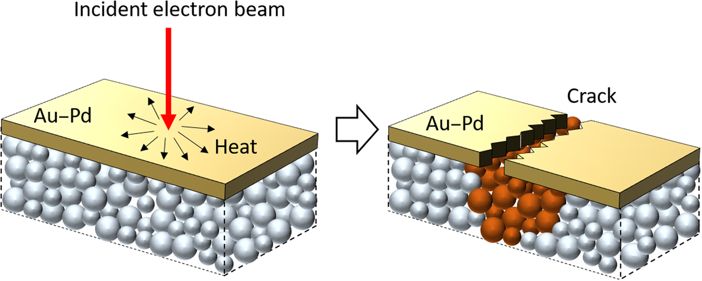
During our SEM imaging, the gun voltage of 5 kV was used to minimize the radiolysis of the sample. This low acceleration voltage slows down the radiolysis of the polymer sample. After focusing at the adjacent area, the beam was directed to the area of interest, and all FE-SEM images in our study were taken within <20 s. Here, the FE-SEM imaging, which typically causes electron charging and subsequent evaporation of non-conducting polymer chains, was possible as a result of following factors. Firstly, the globular structure was visualized from the “cracks” in the conductive surface “shell” of sputtered Au–Pd coating layer, analogous to pomegranate arils visualized in the cracks of the mature fruit's skin. Here, the 5 nm-thick metallic coating has smaller thermal expansion coefficients compared with polymer materials. Upon the electron incidence, cracks formed occasionally in the Au–Pd coating layer due to local heating, revealing the polymer samples in the crack areas, as schematized in Fig. 1. The exposed polymers enjoyed temporal relief from detrimental charge buildup because adjacent metallic coatings dissipated the incident electrons. Secondly, a large amount of salt in the freeze-dried polyampholyte further reduced the polymer sample's vulnerability against electron beam radiation. Since the sensitivity of the sample to the electron irradiation is related to the content of the organic material component, increasing the amount of inorganic components in the sample can improve the stability of the sample under the electron radiation.[Reference Michler and Godehardt25] In our hydrogels, a large amount of NaCl (approximately 20 wt.% when calculated against polymer contents as  $C_{{\rm NaCl}} = m_{{\rm NaCl}}/(m_{{\rm NaCl}} + m_{{\rm polymer}}) \times 100\% $, where C NaCl is the concentration of NaCl, m NaCl is the total mass of NaCl, and m water is the mass of water added in the precursor solution) in the freeze-dried PA-10-2.1 sample reduced the vulnerability of the sample to the electron beam radiation. These particular conditions enabled temporal visualization of nanoscale globules by FE-SEM in our study.
Schematic illustration of crack generation on the polymer and coated metallic layer under electron irradiation.

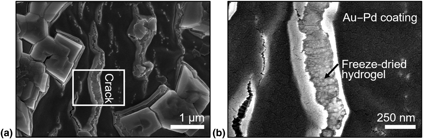
Figure 2 shows the FE-SEM images of the freeze-dried as-prepared hydrogel (PA-10-2.1). Figure 2 shows the spherical structures in the cracks of Au–Pd coating layer. Although it should be noted that FE-SEM is not a reliable method to determine nanoscopic size of polymeric objects, the diameter of the spherical particles (globules, to our model interpretation) is in a reasonable agreement with the expected average diameter of ~5.2 nm according to SAXS fitting.[Reference Li, Charaya, Bernard, Elliott, Michaelis, Lee and Chung20] (It is notable that the radius of a sphere is  $\sqrt {5/3} $ times larger than the radius of gyration.) The spherical shape of the globules are attributed to the ionic coacervation of charged polymer chains.[Reference Hunt, Feldman, Lynd, Deek, Campos, Spruell, Hernandez, Kramer and Hawker26, Reference MacKnight, Taggart and Stein27, Reference Gierke, Munn and Wilson28] The globule structure is ubiquitous and is indeed the universal primary structure in the charge-balanced polyampholyte hydrogel.
(a) The SEM image of freeze-dried polyampholyte hydrogel (PA-10-2.1). (b) Magnified images of the small region identified in (a).

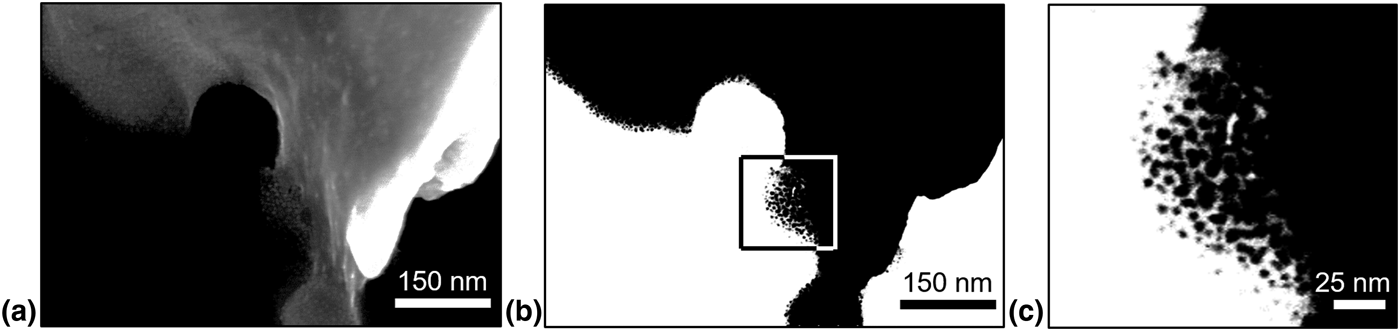
To verify the FE-SEM result, we performed STEM imaging for the ground sample of PA-10-2.1 sample (i.e., powder form). Figure 3(a) is the native bright-field STEM image from the edge of a powder sample. In order to facilitate the visualization of globules, we applied an extreme brightness and contrast adjustment in Fig. 3(b), wherein the enlarged image of boxed region is shown in Fig. 3(c). The STEM images further evidence the existence of globules and their aggregates observed in the FE-SEM images.
(a) The STEM image of the edge of a freeze-dried polyampholyte hydrogel powder. (b) An alternative view of the image in (a) by introducing an extreme brightness and contrast adjustment to facilitate the visualization of globules at the edge of the powder. (c) A magnified image of the small region identified by the rectangular box in (b).

Hydrogel structures of sample dialyzed in DIW and KOH
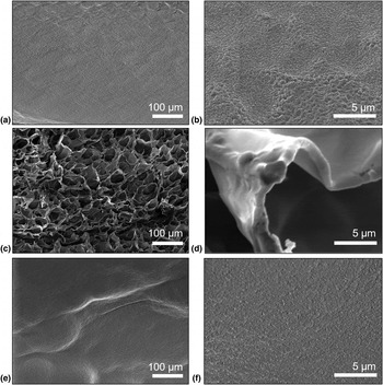
We investigated the impacts of different dialysis solutions for post-treatments on the structures of polyampholyte hydrogels. A piece of as-prepared PA-10-2.1 stored at room temperature was also quenched in liquid nitrogen and freeze-dried as shown in Figs. 4(a) and 4(b). Figures 4(c) and 4(d) show the SEM images of DIW-dialyzed hydrogel of D-PA-10-2.1. The morphology of D-PA-10-2.1 turns into a microscopic cellular structure of polymeric networks with a pore size of ~20 µm after dialysis. The SEM result suggests that salt ions are essential to screen charges of the polymer chains and thereby prevent electrostatic attraction between the polymer chains. After removing NaCl, highly charged polymer chains with opposite charges collapse together.[Reference Kumar and Fredrickson29] In other words, the polyampholyte chains are “zipped” as water and the polymer separate from each other, resulting in the macroscopic structure in Fig. 4(c).[Reference Deek, Chung, Kayser, Bausch and Safinya30]
The SEM image of (a) freeze-dried PA-10-2.1, (c) freeze-dried D-PA-10-2.1, and (e) freeze-dried K-PA-10-2.1. The images (b), (d), and (f) are the zoomed-in images of (a), (c), and (e). All samples were quenched from +20 °C in liquid nitrogen, followed by freeze-drying processes.

The zipping of the polyampholyte chains is crucial to form a tough hydrogel. After the dialysis in DIW, the mobile ions (i.e., Na+ and Cl–) are leaching out from the hydrogel. This process facilitates the formation of ionic bonds between the oppositely charged groups in polyampholyte backbones.[Reference Ihsan, Sun, Kuroda, Haque, Kurokawa, Nakajima and Gong21, Reference Sun, Kurokawa, Kuroda, Ihsan, Akasaki, Sato, Haque, Nakajima and Gong22] Because of the interaction strength of ion bonds, strong and weak ionic bonds have distinguishable properties. Under tensile strain, the strong ionic associations serve as permanent crosslinking points, which keep the shape of the hydrogel. Meanwhile, weak ionic associations act as sacrificial bonds. They break during deformation and dissipate energy. After removing external force, the weak interactions are formed again.[Reference Sun, Kurokawa, Kuroda, Ihsan, Akasaki, Sato, Haque, Nakajima and Gong22] This energy dissipation mechanism makes polyampholyte a class of tough hydrogel.[Reference Sun, Zhao, Illeperuma, Chaudhuri, Oh, Mooney, Vlassak and Suo31]
According to the zipping mechanism described above, one can hypothesize that dialysis in a high ionic strength neutral salt solution may prevent the collapse of the chains. In our previous study, we used KOH as the solution for dialyzing as-prepared hydrogel because the KOH solutions are often used as a solution component for gel electrolytes in the electrochemical storage device.[Reference Li, Liu, Wang, Ok, Elliott, Chang and Chung16] The structures of quenched and freeze-dried K-PA-10-2.1 are shown in Figs. 4(e) and 4(f). The microscopic cellular structure shown in Fig. 4(c) is not observed when the polyampholyte is dialyzed in a 6 M KOH solution, indicating that the electrolyte exchange between NaCl with KOH prevented the zipping. For 6 M KOH case, the direct microscopic observation of globules in the freeze-dried hydrogel was not possible, probably due to the presence of large amount of KOH. Instead, we used indirect methods to obtain clues about nanoscopic morphology of K-PA-10-2.1 sample. In the supporting information, the SAXS fitting (Fig. S1) shows that the nanoscopic globular structures found in PA-10-2.1 sample[Reference Li, Charaya, Bernard, Elliott, Michaelis, Lee and Chung20] is also found in K-PA-10-2.1 sample. It is, however, notable that K-PA-10-2.1 samples showed whitening and stiffening after 6 M KOH dialysis, which may suggest the dissociation of amide group in MPTC monomeric unit in strong basic solution. Although further chemical analysis may provide molecular insight about the mechanism of whitening and stiffening, the SAXS result shows that there is no fundamental change in the nanoscopic structure of polymer chains.
The “non-zipping” of the polyampholyte chains in K-PA-10-2.1 is critical to enhance low-temperature ionic conductivity.[Reference Li, Liu, Wang, Ok, Elliott, Chang and Chung16, Reference Li, Charaya, Bernard, Elliott, Michaelis, Lee and Chung20] Because the globular structure in the polyampholyte hydrogel does not collapse into a microscopic cellular structure, the ice formation in the hydrogel is disrupted upon cooling. When ice forms, the water molecules in interglobular regions firstly transform into ice. Water molecules trapped within the globules do not form ice because they cannot align themselves to form a periodic crystalline molecular alignment, due to either a strong confinement between the polymer chains or to a strong interaction with these chains. As ice crystals grow, the hydrated globules (i.e., polymer-rich domains), which do not participate in the ice formation, come closer to each other. Finally, ice crystals are inhibited from growing freely in size because of steric hindrance from the non-freezable globules and the polyampholyte networks between them that distribute across the entire hydrogel.[Reference Li, Charaya, Bernard, Elliott, Michaelis, Lee and Chung20] The zipped polymer chains in DIW-dialyzed D-PA-10-2.1 allow nearly monolithic growth of ice crystals in the hydrogel when cooled to freezing temperatures because of the large hollow space between microscopic cellular structures of the dialyzed polymer chains. The non-zipped polymer chains in PA-10-2.1 and K-PA-10-2.1, on the other hand, cause disrupted ice formation at the low temperatures, resulting in enhanced ionic conductivity as previously reported.[Reference Li, Liu, Wang, Ok, Elliott, Chang and Chung16, Reference Li, Charaya, Bernard, Elliott, Michaelis, Lee and Chung20]
Conclusion
In this study, we investigated the structure of a charge-balanced polyampholyte, poly(NaSS-co-NPTC) using low-dose FE-SEM and STEM, for the first time. Nanoscale globules in polyampholyte hydrogels were visualized; the globules has been theoretically predicted and experimentally supported by SAXS. In addition, we studied the impact of dialysis processes on microscopic structure of polymer networks, which is directly relevant to the mechanical properties and ice formation of the polyampholyte hydrogels. The structure of hydrogels dialyzed in DIW suggests the zipping trend of the polyampholyte chains, which is crucial to form a tough hydrogel. After removing NaCl, highly charged polymer chains with opposite charges collapse (or zip) to form microscopic (pore sizes of 10s of μm) cellular structure. The zipped polymer chain structure is crucial to make a tough hydrogel.[Reference Sun, Kurokawa, Kuroda, Ihsan, Akasaki, Sato, Haque, Nakajima and Gong22] Such zipping phenomenon is not found when the as-prepared hydrogel was dialyzed in 6 M KOH solution. There is no visible microscopic structure in the KOH-dialyzed sample; the absence of microscopic structure is helpful in achieving disrupted ice formation at low temperatures.[Reference Li, Liu, Wang, Ok, Elliott, Chang and Chung16, Reference Li, Charaya, Bernard, Elliott, Michaelis, Lee and Chung20]
Supplementary material
The supplementary material for this article can be found at https://doi.org/10.1557/mrc.2018.149
Acknowledgments
The authors gratefully acknowledge funding from a NSERC DG (RGPIN 435914). Material characterization was partly done in the shared facility of the NanoFAB in the Faculty of Engineering at the University of Alberta. The use of the Advanced Photon Source was supported by the US DOE under Contract DE-AC02-06CH11357.