Nomenclature
-
 $h$
-
altitude
-
${h_{{\textrm{ref}}}}$
-
reference altitude
-
$V$
-
velocity
-
${V_{{\textrm{ref}}}}$
-
reference velocity
-
$p$
-
roll rate
-
$q{\textrm{}}$
-
pitch rate
-
$r$
-
yaw rate
-
${\textbf{X}}$
-
displacement vector
-
${\textbf{V}}$
-
velocity vector
-
${\textbf{e}}$
-
error vector
-
${\textbf{g}}$
-
acceleration due-to-gravity vector
-
$m$
-
mass
-
$T$
-
thrust
-
$D$
-
drag
-
$Q$
-
dynamic pressure
-
${S_{{\textrm{ref}}}}$
-
reference surface area
-
${C_D}$
-
drag coefficient
-
${C_{{L_\alpha }}}$
-
lift coefficient derivative with respect to
$\alpha $
-
${C_{{L_\beta }}}$
-
lift coefficient derivative with respect to
$\beta $
-
$\mathcal{L}$
-
aerodynamic and propulsive moment vector about body
$x$
axis -
$\mathcal{M}$
-
aerodynamic and propulsive moment vector about body
$y$
axis -
$\;\mathcal{N}$
-
aerodynamic and propulsive moment vector about body
$z$
axis -
${J_x}$
-
moment of inertia about body
$x$
axis -
${J_y}$
-
moment of inertia about body
$y$
axis -
${J_z}$
-
moment of inertia about body
$z$
axis -
${S^ \times }({\cdot})$
-
skew symmetric cross product matrix
-
${C_{{m_x}}}$
-
pitching moment coefficient about body
$x$
axis -
$l$
-
vehicle length
-
${R_e}$
-
Earth’s equatorial radius
-
${R_L}$
-
local Earth’s radius
-
${b_{\textrm{rud}}}$
-
distance between centre of motor and vehicle’s longitudinal axis
-
${X_{\textrm{cg}}}$
-
distance from the vehicle’s nose to its centre of mass
-
${X_{\textrm{cp}}}$
-
distance from the vehicle’s nose to its centre of pressure
-
${X_{\textrm{rud}}}$
-
distance from the vehicle’s nose to the motor’s hinge line
-
$\mathcal{P}$
-
null projection matrix


Greek symbol
-
$\vartheta $
-
flight path angle
-
${\vartheta _{{\textrm{ref}}}}$
-
reference flight path angle
-
$\alpha $
-
angle-of-attack
-
$\sigma $
-
heading angle
-
$\beta $
-
side slip angle
-
$\phi $
-
roll angle
-
$\theta $
-
pitch angle
-
$\psi $
-
yaw angle
-
$\vartheta_l$
-
local flight path angle
-
${\omega _e}$
-
Earth’s rotational speed
-
${\delta _\phi }$
-
roll control deflection
-
${\delta _\theta }$
-
pitch control deflection
-
${\delta _\psi }$
-
yaw control deflection
-
$\lambda $
-
latitude
-
$\xi $
-
attitude error deviation function
-
$\eta $
-
null control vector
-
$\nu $
-
dynamic scaling factor
-
$\zeta $
-
body rate deviation function
-
$\Delta$
-
attitude corrections
-
${\epsilon _y}$
-
normal positional error
-
${\epsilon _z}$
-
lateral positional error
-
$\nabla $
-
thrust offset
-
$\varrho $
-
thrust misalignment


1.0 Introduction
The attitude control system design for Satellite Launch Vehicles (SLVs) has been an active area of research for the last three decades. The factors that make it challenging to design a robust SLV flight control system include the highly complex nonlinear SLV dynamics, the big variations in aerodynamic loads and propulsive forces throughout the flight envelope, inertia and aerodynamic parametric uncertainties of the SLV, in addition to wind and other exogenous disturbances that the SLV may be exposed to.
The vast majority of practical control system designs that were proposed initially for SLVs were linear. To overcome SLV control performance degradations that result from neglecting high nonlinearities in the SLV dynamics, gain scheduling of the linear control system parameters were used to be implemented [Reference Reichert1–Reference Clement, Duc and Mauffrey4]. However, gain scheduling methods are costly and became needless with the recent advancements in nonlinear control systems.
The focus has been shifting during the last two decades towards designing modern SLV control systems that overcome the limitations of classical linear control systems and the complexity of gain scheduling. A variety of nonlinear control system methodologies are now found in the SLV control literature, e.g. dynamic inversion with backstepping control [Reference Steinicke and Michalka5], Sliding Mode Control (SMC) [Reference Wang, Liu, Wang and Wang6], fault-tolerant control [Reference Das, Sen and Dasgupta7, Reference Das, Sen and Dasgupta8], adaptive control [Reference Ansari and Bajodah9, Reference Johnson, Calise and Corban10] and intelligent control [Reference Ansari11–Reference Ansari and Alam13].
Among the popular nonlinear control system design methodologies is global feedback linearisation via Nonlinear Dynamic Inversion (NDI). The NDI control law is designed to eliminate system nonlinearities by means of feedback. As a consequence, well-established linear control techniques can be incorporated in the outer feedback control loop. In NDI, however, the linearised system is obtained by direct nonlinearity cancellation. Therefore, the methodology is heavily dependent on the mathematical model of the controlled system.
As a consequent, dynamic inversion errors of a poorly modeled plant dynamics degrade an NDI control system stability and performance by a big extent [Reference Pedro, Panday and Dala14]. Numerous modifications were made to the NDI control system structure to improve its robustness [Reference McFarland and Hoque15–Reference Doman and Ngo17]. However, some limitations of feedback linearisation via NDI remain problematic, including useful nonlinearities cancellations, large NDI control efforts, squaring assumptions and approximations of nonsquare controlled plants, and singularity configurations of the controlled system matrix.
Generalised Dynamic Inversion (GDI) [Reference Bajodah, Hodges and Chen18–Reference Hameduddin and Bajodah23] is a dynamic inversion control design methodology that avoids many disadvantages of classical NDI. The GDI control design methodology provides the ability of partial feedback linearisation of the closed loop dynamics, and it provides the flexibility of involving other control system design methodologies within the dynamic inversion framework, e.g. energy-based control techniques.
Therefore, the GDI control methodology avoids blind cancellation of plant nonlinearities and makes it possible to reduce the control effort that is required to execute dynamic inversion. Finally, the GDI control methodology is based on the nonsquare Moore-Penrose Generalised Inversion (MPGI) tool [Reference Moore24, Reference Penrose25]. Hence, GDI control bypasses the plant squaring assumptions and approximation tactics, and it is not affected by the controlled system square matrix singularity configurations.
The GDI control methodology is rooted in analytical dynamics [Reference Udwadia and Kalaba26], and it was inspired by the MPGI-based Greville formula [Reference Greville27, Reference Ben-Israel and Greville28] for solving linear algebraic systems of equations. The GDI control law is composed of two cooperating control parts that act on two orthogonally complement control spaces: one part is a particular part that realises the dynamic constraints, and the other is an auxiliary part that is affine in a null control vector. Orthogonality of the particular and the auxiliary control subspaces guarantees noninterference of the two control actions, and thus it ensures that both actions work towards a unified goal, and work to reduce the total control effort.
A GDI nonlinear control system design begins by prescribing a desired Servo Constraint Dynamics (SVD) that encapsulates the GDI control design objectives. The SVD is generalised inverted for the control variables that realise that dynamics by using a modification of the Greville formula. The modified Greville formula is constructed by scaling the MPGI in the particular part of the formula by a dynamic factor. The Dynamically Scaled Generalised Inverse (DSGI) avoids MPGI singularity as the controlled system dynamics evolves. The nonempty nullspace of the nonsquare generalised-inverted matrix in the modified Greville formula is utilised to perform other objectives of the GDI control design, mainly for stabilising the inner dynamics of the closed loop GDI control system. The GDI control methodology has been applied to numerous aerospace engineering and robotics applications [Reference Bajodah, Hodges and Chen18–Reference Hameduddin and Bajodah23, Reference Ansari and Bajodah29–Reference Bajodah34].
The present paper extends the authors’ previous works on SLV GDI control [Reference Ansari and Bajodah29, Reference Ansari and Bajodah30]. The baseline GDI control methodology is modified by applying GDI control in a successive manner to design the null control vector in the auxiliary part of the GDI control law on top of its application to design the particular part of the GDI control law. The particular part of the Successive GDI (SGDI) control law employs GDI on an SVD in the SLV’s Euler attitude angles, and it is responsible for controlling the SLV’s outer dynamics. The auxiliary part of the SGDI control law employs GDI on an SVD in the SLV’s angular velocity variables, and it is responsible for controlling the SLV’s inner dynamics.
Due to the favourable geometry of the Greville formula, the order in which the attitude and the inner-dynamics loops closures is performed is irrelevant and can be performed arbitrarily to achieve the same SGDI closed loop dynamics. To enhance SGDI control performance robustness against SLV modeling uncertainties and exogenous disturbances and generalised inversion dynamic scaling, integral control elements are augmented within the attitude and the inner-dynamics loops of the baseline SGDI control system. The performance-robustifying control elements are augmented in a manner that maintains geometrical features of the nominal SGDI control law.
The proposed robust SGDI control system is validated by numerical simulations on a six Degrees Of Freedom (DOFs) simulator of a four-stage SLV subjected to inertial, aerodynamic and propulsive parametric uncertainties under unsteady wind effects. Moreover, the proposed control system is compare with a classical SMC control system, the second of which is known for its high, robust performance. Finally, diversified Monte-Carlo statistical simulations are carried out to verify robustness attributes of the SLV robust SGDI control system in the presence of internal perturbations and environmental disturbances.
In the realm of SLV attitude control systems, the major contribution of this article is threefold. First, a novel variant of GDI control is introduced for controlling the complex coupled nonlinear SLV attitude dynamics under environmental challenges. The control actions on the outer and inner SLV dynamics work synergistically without interference towards robust SLV attitude control. Second, a detailed Lyapunov stability-based analysis is presented to prove asymptotic convergence of the state variables to their optimal reference trajectories. Third, numerical simulations supported with diversified Monte-Carlo analysis are carried out to validate efficacy of SGDI control in the presence of model uncertainties and environmental disturbances.
The remaining part of the paper is organised as follows. Mathematical modeling of the SLV is presented in Section 2. Section 3 elucidates the baseline SGDI control system design, and Section 4 delves into SGDI control system robustification. Section 5 describes the optimal reference trajectory generation methodology, and elaborates the trajectory reshaping strategy and rational energy management. Numerical simulations of the proposed robust SGDI SLV control system are shown in Section 6, in addition to performance evaluation of the proposed system by comparisons with a SMC system and through Monte Carlo simulations. The paper is concluded in Section 7.
2.0 Six-DOFs mathematical modeing
In developing a mathematical model for the SLV’s kinematics and dynamics, the Earth is assumed to be ellipsoidal, and its rotation together with the atmosphere is taken as a single frame of reference. The effect of Earth’s rotation is also taken into account by modeling the Coriolis and the centrifugal accelerations. The synergy between the Earth and the SLV is modeled with the aid of the two-body problem formulation. The SLV’s six DOFs kinematics is given by the following translational and rotational kinematical equations of motion [Reference Xiao35]
 \begin{align} {\dot{\textbf{X}}_l} & = {{\textbf{V}}_l}, \\[-10pt] \nonumber \end{align}
 \begin{align} \dot \phi & = p + q\;{\textrm{tan}}\;\psi \;{\textrm{sin}}\;\phi + r\;{\textrm{cos}}\;\phi \;{\textrm{tan}}\;\psi \\[-10pt] \nonumber \end{align}
 \begin{align} \dot \theta & = q\;{\textrm{sin}}\;\phi /\;{\textrm{cos}}\;\psi + r\;{\textrm{cos}}\;\phi /\;{\textrm{cos}}\;\psi \\[-10pt] \nonumber \end{align}
 \begin{align} \dot \psi & = q\;{\textrm{cos}}\;\phi - r\;{\textrm{sin}}\;\phi . \\[6pt] \nonumber\end{align}
In Equation (1),
 ${{\textbf{X}}_l} = {[{x_l}{{\;\;\;\;}}{y_l}{{\;\;\;\;}}{z_l}]^T}$
, where
 ${x_l}$
,
 ${y_l}$
, and
 ${z_l}$
are the displacement vector components of the SLV from its launch site, expressed in the Launch Reference Frame (LRF), and
 ${{\textbf{V}}_l} = {[{V_{{x_l}}}{{\;\;\;\;}}{V_{{y_l}}}{{\;\;\;\;}}{V_{{z_l}}}]^T}$
, where
 ${V_{{x_l}}}$
,
 ${V_{{y_l}}}$
, and
 ${V_{{z_l}}}$
are the velocity vector components of the SLV relative to the LRF. The SLV’s three translational DOFs dynamical equations of motion are given by [Reference Xiao35]
 \begin{align}{{\dot{\textbf{V}}}_l} = \frac{{{L_{lb}}}}{m}\left[ {\begin{array}{*{20}{l}}{ - Q{S_{{\textrm{ref}}}}{C_D} + T\;{\textrm{cos}}\;{\delta _\phi }}\\[3pt] {Q{{\textrm{S}}_{{\textrm{ref}}}}{C_{{L_\alpha }}} + 0.5T\,{\textrm{sin}}\;{\delta _\theta }}\\[3pt] {Q{S_{{\textrm{ref}}}}{C_{{L_\beta }}} + 0.5T\,{\textrm{sin}}\;{\delta _\psi }}\end{array}} \right] + {L_{le}}{{\textbf{g}}_e} - {L_{le}} \Omega_e^ \times \Omega_e^ \times {{\textbf{X}}_e} - 2{L_{le}} \Omega_e^ \times {{\textbf{V}}_e}. \end{align}
In Equation (5),
 ${{\textbf{X}}_e} = {[{x_e}{{\;\;\;\;}}{y_e}{{\;\;\;\;}}{z_e}]^T}$
, where
 ${x_e}$
,
 ${y_e}$
, and
 ${z_e}$
are the displacement vector components of the SLV from its launch site, expressed in the earth-fixed Geocentric Reference Frame (GRF), and
 ${{\textbf{V}}_e} = {[{V_{{x_e}}}{{\;\;\;\;}}{V_{{y_e}}}{{\;\;\;\;}}{V_{ze}}]^T}$
, where
 ${V_{{x_e}}}$
,
 ${V_{{y_e}}}$
, and
 ${V_{{z_e}}}$
are the SLV’s velocity vector components relative to the GRF. Similarly,
 ${{\textbf{g}}_e} = {[{g_{xe}}{{\;\;\;\;}}{g_{ye}}{{\;\;\;\;}}{g_{ze}}]^T}$
, where
 ${g_{xe}}$
,
 ${g_{ye}}$
, and
 ${g_{ze}}$
are the acceleration-due-to gravity vector components in the GRF. The variable
 $ \Omega_e^ \times $
denotes the skew symmetric cross product matrix of the vector
 ${{\boldsymbol{\Omega }}_e} = {[0{{\;\;\;\;}}0{{\;\;\;\;}}{\omega _e}]^T}$
, and is given by
 \begin{align} \Omega_e^ \times = \left[ \begin{array}{c@{\quad}c@{\quad}c} 0 & {}{ - {\omega _e}} & {}0\\[3pt] {{\omega _e}} & {}0 {}& 0\\[3pt] 0 & {}0 & {}0\end{array} \right], \end{align}
The matrices
 ${L_{lb}},{L_{le}} \in {\mathbb{R}^{3 \times 3}}$
are the transformation matrices from the Body-fixed Reference Frame (BRF) to the LRF and from the GRF to the LRF, respectively. Also, The SLV’s three rotational DOFs dynamical equations of motion in the SLV’s BRF are given by [Reference Xiao35]
 \begin{align} \dot p & = \mathcal{L}/{J_x} \\[-10pt] \nonumber \end{align}
 \begin{align} \dot q & = \left( {{J_z} - {J_x}} \right)pr/{J_y} + \mathcal{M}/{J_y} \\[-10pt] \nonumber \end{align}
 \begin{align} \dot r & = - \frac{{\left( {{J_y} - {J_x}} \right)pq}}{{{J_z}}} + \frac{\mathcal{N}}{{{J_z}}}, \\[-10pt] \nonumber \end{align}
 \begin{align} \theta & = \vartheta + \alpha, {{\;\;\;\;\;\;\;\;\;}}\psi = \sigma + \beta . \\[6pt] \nonumber \end{align}
The moment components
 $\mathcal{L}$
,
 $\mathcal{M}$
, and
 $\mathcal{N}$
in Equations (7)–(10) are composed of aerodynamic moments, control moments and disturbance moments due to thrust misalignment [Reference Xiao35]. The aerodynamic moment components in the BRF are given by Equations (11)–(13)
 \begin{align} {\mathcal{L}_a} & = Q{S_{{\textrm{ref}}}}l{C_{{m_x}}} \\[-10pt] \nonumber \end{align}
 \begin{align} {\mathcal{M}_a} & = - Q{S_{{\textrm{ref}}}}{C_{{L_\alpha }}}\alpha \! \left( {{X_{\textrm{cp}}} - {X_{\textrm{cg}}}} \right), \\[-10pt] \nonumber \end{align}
 \begin{align} {\mathcal{N}_a} & = Q{S_{{\textrm{ref}}}}{C_{{L_\beta }}}\beta \! \left( {{X_{\textrm{cp}}} - {X_{\textrm{cg}}}} \right). \\[6pt] \nonumber \end{align}
The control moments in the BRF are given by Equations (14)–(16)
 \begin{align} {\mathcal{L}_\delta } & = T{b_{\textrm{rud}}}{\delta _\phi } \\[-10pt] \nonumber \end{align}
 \begin{align} {\mathcal{M}_\delta } & = \frac{1}{2}T\left( {{X_{\textrm{rud}}} - {X_{\textrm{cg}}}} \right){\delta _\theta }, \\[-10pt] \nonumber \end{align}
 \begin{align} {\mathcal{N}_\delta } & = \frac{1}{2}T\left( {{X_{\textrm{rud}}} - {X_{\textrm{cg}}}} \right){\delta _\psi }. \\[6pt] \nonumber \end{align}
Finally, the moments caused by disturbances due to misalignment of the thrust vector
 $\varrho $
from the SLV’s centre of mass are caused by the thrust offset
 $\nabla $
relative to the centre of mass, and are expressed in the BRF as seen in Equations (17)–(19)
 \begin{align} {\mathcal{L}_\varrho } & = T{\textrm{sin}}\left( \varrho \right){\nabla _T}, \\[-10pt] \nonumber \end{align}
 \begin{align} {\mathcal{M}_\varrho } & = \frac{1}{2}T{\textrm{sin}}\left( \varrho \right)\left( {{X_{\textrm{rud}}} - {X_{\textrm{cg}}}} \right) + \frac{1}{2}T{\nabla _T}, \\[-10pt] \nonumber \end{align}
 \begin{align} {\mathcal{N}_\varrho } & = \frac{1}{2}T{\textrm{sin}}\left( \varrho \right)\left( {{X_{\textrm{rud}}} - {X_{\textrm{cg}}}} \right) + \frac{1}{2}T{\nabla _T}. \\[6pt] \nonumber \end{align}
By combining the moment components about each BRF axis as given by Equations (11)–(19), the following expressions for aerodynamic, propulsive and thrust misalignment moment components are obtained
 \begin{align} \mathcal{L} & = Q{S_{{\textrm{ref}}}}l{C_{{m_x}}} + T{b_{\textrm{rud}}}{\delta _\phi } + T{\textrm{sin}}\left( \varrho \right){\nabla _T} \\[-10pt] \nonumber \end{align}
 \begin{align} \mathcal{M} & = - Q{S_{{\textrm{ref}}}}{C_{{L_\alpha }}}\alpha \left( {{X_{\textrm{cp}}} - {X_{\textrm{cg}}}} \right) + 0.5T\left( {{X_{\textrm{rud}}} - {X_{\textrm{cg}}}} \right){\delta _\theta } + 0.5T{\textrm{sin}}\left( \varrho \right)\left( {{X_{\textrm{rud}}} - {X_{\textrm{cg}}}} \right) + 0.5T{\nabla _T}, \\[-10pt] \nonumber \end{align}
 \begin{align} \mathcal{N} & = Q{S_{{\textrm{ref}}}}{C_{{L_\beta }}}\beta \left( {{X_{\textrm{cp}}} - {X_{\textrm{cg}}}} \right) + 0.5T\left( {{X_{\textrm{rud}}} - {X_{\textrm{cg}}}} \right){\delta _\psi } + 0.5T{\textrm{sin}}\left( \varrho \right)\left( {{X_{\textrm{rud}}} - {X_{\textrm{cg}}}} \right) + 0.5T{\nabla _T}. \\[6pt] \nonumber \end{align}
Let the attitude state vector of the SLV be defined as
 ${\textbf{x}} = {[\phi {{\;\;\;\;}}\theta {{\;\;\;\;}}\psi {{\;\;\;\;}}p{{\;\;\;\;}}q{{\;\;\;\;}}r]^T}$
, and let the control vector of the SLV be defined as
 ${\textbf{u}} = {[{\delta _\phi }{{\;\;\;\;}}{\delta _\theta }{{\;\;\;\;}}{\delta _\psi }]^T}$
. Also, let the state vector
 ${\textbf{x}}$
be partitioned as
 \begin{align}{{\textbf{x}}_o} = \left[ {\phi {{\;\;\;}}\theta {{\;\;\;}}\psi {]^T},{{\;\;\;}}{{\textbf{x}}_i} = } \right[p{{\;\;\;}}q{{\;\;\;}}r{]^T} \end{align}
where
 ${{\textbf{x}}_o}$
is the vector of outer (unactuated) attitude state variables, and
 ${{\textbf{x}}_i}$
is the vector of inner (actuated) angular velocity state variables. Hence, the unactuated attitude dynamics given by Equations (2), (3) and (4) may be written compactly as
 \begin{align}{{\dot{\textbf{x}}}_o} = H\left( {{{\textbf{x}}_o}} \right){{\textbf{x}}_i} \end{align}
where
 \begin{align}H\left( {{{\textbf{x}}_o}} \right) = \left[ {\begin{array}{c@{\quad}c@{\quad}c} 1 & {}{{\textrm{tan}}\,\psi\, {\textrm{sin}}\,\phi } & {}{{\textrm{cos}}\,\phi\, {\textrm{tan}}\,\psi } \\[3pt] 0 & {}{{\textrm{sin}}\,\phi /{\textrm{cos}}\,\psi } & {}{{\textrm{cos}}\, \phi /{\textrm{cos}}\,\psi } \\[3pt] 0 & {}{{\textrm{cos}}\,\phi } & {}{ - {\textrm{sin}}\,\phi } \end{array}} \right]. \end{align}
Also, the actuated inner velocity dynamics given by Equations (7), (8) and (9) can be written compactly as
 \begin{align}{{\dot{\textbf{x}}}_i} = - {J^{ - 1}}{S^ \times }\left( {{{\textbf{x}}_i}} \right)J{{\textbf{x}}_i} + {J^{ - 1}}{\textbf{M}} \end{align}
where
 ${S^ \times }( {{{\textbf{x}}_i}})$
is given by
 \begin{align}{S^ \times }\left( {{{\textbf{x}}_i}} \right) = \left[ {\begin{array}{c@{\quad}c@{\quad}c} 0 {}& { - r} & {}q\\[3pt] r & {}0 & {}{ - p}\\[3pt] { - q} & {}p & {}0\end{array}} \right] \end{align}
In Equation (26),
 $J = diag\left( {{J_x},{J_y},{J_z}} \right)$
is the diagonal matrix containing
 ${J_x}$
,
 ${J_y}$
, and
 ${J_z}$
in its diagonal entries, and
 ${\textbf{M}} = {[\mathcal{L}\;\;\;\;\mathcal{M}\;\;\;\;\mathcal{N}]^T}$
. Substituting the expressions given by Equations (20), (21) and (22) in Equation (26) yields
 \begin{align}{{\dot{\textbf{x}}}_i} = - {J^{ - 1}}{S^ \times }\left( {{{\textbf{x}}_i}} \right)J{{\textbf{x}}_i} + {J^{ - 1}}Q{S_{{\textrm{ref}}}}{\textbf{f}}\left( {\alpha, \beta } \right) + {J^{ - 1}}G{\textbf{u}} \end{align}
where
 \begin{align}{\textbf{f}}\left( {\alpha, } \right) = \left[ {\begin{array}{c}{l{C_{{m_x}}}} \\[3pt] { - {C_{{L_\alpha }}}\alpha \left( {{X_{\textrm{cp}}} - {X_{\textrm{cg}}}} \right)} {} \\[3pt] {{C_{{L_\beta }}}\beta \left( {{X_{\textrm{cp}}} - {X_{\textrm{cg}}}} \right)} \end{array}} \right], \end{align}
 \begin{align}G = \left[ {\begin{array}{c@{\quad}c@{\quad}c}{T{b_{\textrm{rud}}}} & {}0 & {}0 \\[3pt] 0 & {}{0.5T\left( {{X_{\textrm{rud}}} - {X_{\textrm{cg}}}} \right)} {} & 0 {} \\[3pt] 0 & {}0 & {}{0.5T\left( {{X_{\textrm{rud}}} - {X_{\textrm{cg}}}} \right)} {}, {}\end{array}} \right], \end{align}
and
 \begin{align}{\textbf{u}} = {[{\delta _\phi }{{\;\;\;}}{\delta _\theta }{{\;\;\;}}{\delta _\psi }]^T}. \end{align}
Finally, Equation (28) is rewritten more compactly as
 \begin{align}{{\dot{\textbf{x}}}_i} = {\textbf{A}} + B{\textbf{u}} \end{align}
where
 \begin{align}{\textbf{A}} = - {J^{ - 1}}{S^ \times }\left( {{{\textbf{x}}_i}} \right)J{{\textbf{x}}_i} + {J^{ - 1}}Q{S_{{\textrm{ref}}}}{\textbf{f}}\left( {\alpha, \beta } \right), \end{align}
and
 $B$
is the full-rank control influence matrix given by
 \begin{align}B = {J^{ - 1}}G. \end{align}
3.0 Baseline SGDI feedback control system design
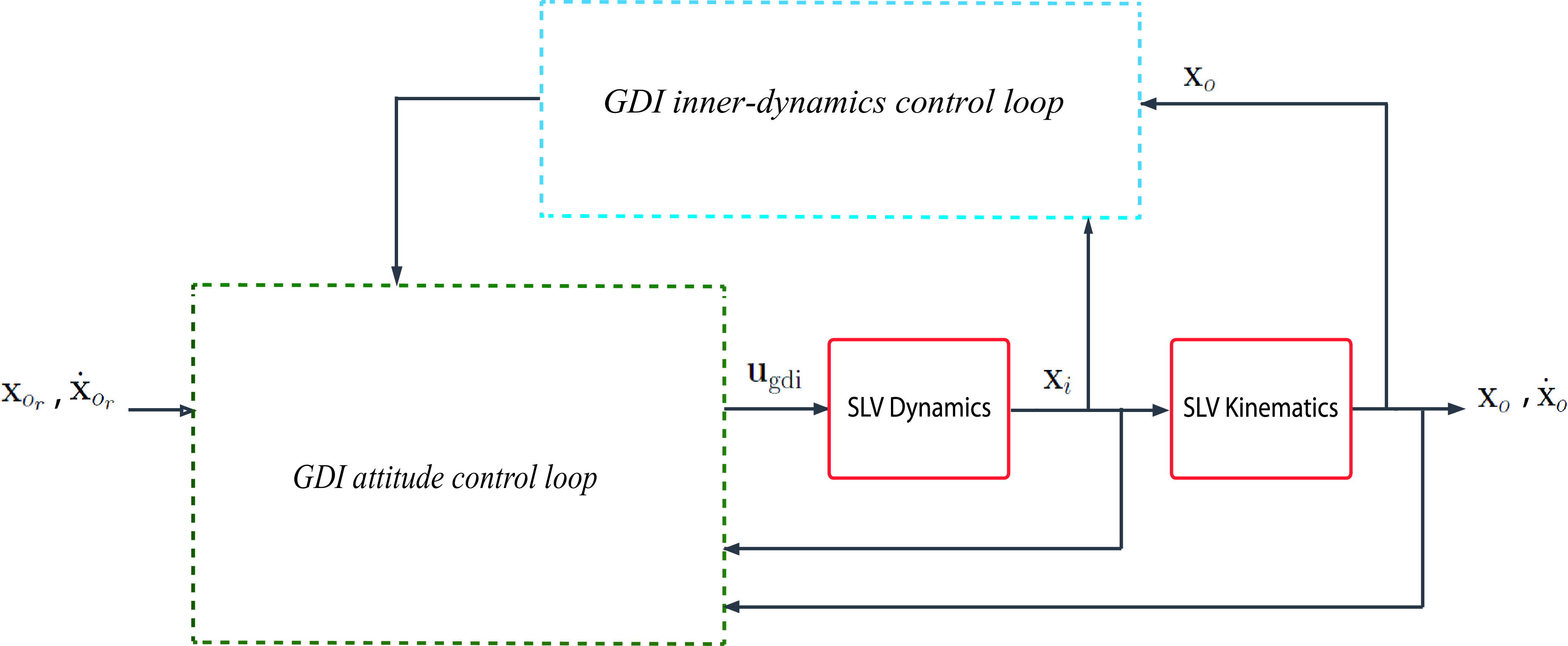
The SGDI control system is the backbone of the proposed robust SGDI control system. The SGDI control system is composed of two GDI control loops as illustrated in Fig. 1. The guidance system feeds the reference attitude trajectories to the GDI attitude control loop, which works to control the attitude dynamics given by Equation (24) such that the attitude variables track the reference attitude trajectories. The GDI inner-dynamics control loop works to stabilise the inner (angular velocity) dynamics of the SLV given by Equation (26).
General SGDI control system structure: the inner loop controls SLV’s internal dynamics, and the outer loop controls SLV’s attitude dynamics.

3.1 GDI attitude control loop design
The first step in designing the attitude control loop of the baseline SGDI control system is to prescribe a time differential SVD that resembles the SLV’s desired attitude trajectories deviation dynamics from their desired trajectories. Hence, the outer (attitude) error vector is defined as
 \begin{align}{{\textbf{e}}_o} = {{\textbf{x}}_o} - {{\textbf{x}}_{{o_r}}}\left( t \right), \end{align}
where
 ${{\textbf{x}}_{{o_r}}}\left( t \right) = {[{\phi _r}\left( t \right){{\;\;\;}}{\theta _r}\left( t \right){{\;\;\;}}{\psi _r}\left( t \right)]^T}$
is a bounded twice differentiable reference attitude angles vector function. The attitude error deviation function is defined as
 \begin{align}\xi = \frac{1}{2}{\textbf{e}}_o^T{K_o}{{\textbf{e}}_o} \end{align}
where
 ${K_o} \in {\mathbb{R}^{3 \times 3}}$
is a positive definite constant matrix such that
 $\xi $
vanishes if and only if the attitude state trajectories converge to the corresponding desired attitude state trajectories. To fulfill that purpose, an asymptotically stable SVD in
 $\xi $
is prescribed and is enforced by means of GDI control. The SVD takes the following Linear Time Invariant (LTI) form
 \begin{align}\ddot \xi + {a_1}\dot \xi + {a_2}\xi = 0,{{\;\;\;}}{a_1} \gt 0,\;{a_2} \gt 0 \end{align}
where the order (two) of the SVD is equal to of the relative degree of
 $\xi $
with respect to
 ${\textbf{u}}$
, such that
 $\left( {\xi, \dot \xi } \right) = {0_2}$
is globally asymptotically stable [Reference Bajodah20]. The first and second time derivatives of
 $\xi $
are
 \begin{align}\dot \xi = {\textbf{e}}_o^T{K_o}{{\dot{\textbf{e}}}_o} \end{align}
and
 \begin{align}\ddot \xi = {\textbf{e}}_o^T{K_o}\left( {{{\boldsymbol{\Delta}}_o} + H\left( {{{\textbf{x}}_o}} \right)B{\textbf{u}}} \right) + {\dot{\textbf{e}}}_o^T{K_o}{{\dot{\textbf{e}}}_o} \end{align}
where
 \begin{align}{{\dot{\textbf{e}}}_o} = H\left( {{{\textbf{x}}_o}} \right){{\textbf{x}}_i} - {{\dot{\textbf{x}}}_{{o_r}}}, \end{align}
and
 \begin{align}{{\boldsymbol{\Delta}}_o} = H\left( {{{\textbf{x}}_o}} \right){\textbf{A}} + \dot H\left( {{{\textbf{x}}_o},{{\textbf{x}}_i}} \right){{\textbf{x}}_i} - {{\dot{\textbf{x}}}_{{o_r}}} \end{align}
such that
 $\dot H\left( {{{\textbf{x}}_o},{{\textbf{x}}_i}} \right)$
is the element-wise time derivative of
 $H\left( {{{\textbf{x}}_o}} \right)$
. By substituting the time derivatives given by Equations (38) and (39) in the SVD given by Equation (37), the differential form of the SVD is converted to the following algebraic form
 \begin{align}{\mathcal{A}_o}{\textbf{u}} = {\mathcal{B}_o}, \end{align}
where
 \begin{align}{\mathcal{A}_o} = {\textbf{e}}_o^T{K_o}H\left( {{{\textbf{x}}_o}} \right)B \end{align}
and
 \begin{align}{\mathcal{B}_o} = - {\textbf{e}}_o^T{K_o}{{\boldsymbol{\Delta}}_o} - {\dot{\textbf{e}}}_o^T{K_o}{{\dot{\textbf{e}}}_o} - {a_1}\dot \xi - {a_2}\xi . \end{align}
Equation (42) is over-determined in
 ${\textbf{u}}$
and is consistent for all
 ${{\textbf{e}}_o} \ne {0_3}$
. Therefore, Equation (42) has infinite number of solutions. The solutions for
 ${\textbf{u}}$
are parameterised by an arbitrary outer null control vector
 ${\eta _o} \in {\mathbb{R}^3}$
in the MPGI-based Greville formula as
 \begin{align}{\textbf{u}} = \underbrace {\mathcal{A}_o^ + {\mathcal{B}_o}}_{ \in \mathcal{R}\left( {\mathcal{A}_o^T} \right)} + \underbrace {{\mathcal{P}_o}{\eta }_o}_{ \in \mathcal{N}\left( {{\mathcal{A}_o}} \right)}, \end{align}
where
 $\mathcal{A}_o^ + $
is the MPGI of
 ${\mathcal{A}_o}$
, and is given as
 \begin{align}\mathcal{A}_o^ + = \left\{ {\begin{array}{c@{\quad}c} {\mathcal{A}_o^T/\left( {{\mathcal{A}_o}\mathcal{A}_o^T} \right)} {}& {}{{\mathcal{A}_o} \ne {0_{1 \times 3}}}\\[3pt] {{0_3}} {}& {}{{\mathcal{A}_o} = {0_{1 \times 3}}}\end{array}} \right. \end{align}
and
 ${\mathcal{P}_o}$
is the null projection matrix on the nullspace of
 ${\mathcal{A}_o}$
, and is given by
 \begin{align}{\mathcal{P}_o} = {{\dot{\textbf{I}}}_{3 \times 3}} - \mathcal{A}_o^ + {\mathcal{A}_o}. \end{align}
The control vector
 ${\textbf{u}}$
is composed of a particular part
 $\mathcal{A}_o^ + {\mathcal{B}_o}$
and an auxiliary part
 ${\mathcal{P}_o}{\eta _o}$
. The particular part of
 ${\textbf{u}}$
acts on the range space
 $\mathcal{R}\left( {\mathcal{A}_o^T} \right)$
, and it works to enforce the SVD given by Equation (42). The auxiliary part of
 ${\textbf{u}}$
acts on the orthogonally complement nullspace
 $\mathcal{N}\left( {{\mathcal{A}_o}} \right)$
such that
 ${\textrm{r}}ank\left( {\mathcal{A}_o^T} \right) + {\textrm{r}}ank\left( {{\mathcal{P}_o}} \right) = {\textrm{dim}}\left( {\textbf{u}} \right) = 3$
. The value of
 ${\eta _o}$
does not affect the SVD enforcement because the null projection matrix
 ${\mathcal{P}_o}$
projects
 ${\eta _o}$
on
 $\mathcal{N}\left( {{\mathcal{A}_o}} \right)$
. The vector
 ${\eta _o}$
is designed to stabilise the inner dynamics of the SLV as shown later in the paper. Because
 $\mathcal{A}_o^ + $
is a nonzero single column matrix, it follows that
 ${\textrm{r}}ank\left( {{\mathcal{P}_o}} \right) = {\textrm{dim}}\left( {\textbf{u}} \right) - {\textrm{r}}ank\left( {\mathcal{A}_o^ + } \right) = 3 - 1 = 2$
. However, the MPGI
 $\mathcal{A}_o^ + $
is a discontinuous function at
 ${{\textbf{e}}_o} = {0_3}$
, and it reaches infinite values in the neighbourhood of
 ${{\textbf{e}}_o} = {0_3}$
where
 ${\mathcal{A}_o}$
and
 $\mathcal{A}_o^ + $
approach
 ${0_{1 \times 3}}$
and
 $ = {0_3}$
, respectively according to Equation (46). Therefore, utilising the Greville formula given by Equation (45) is hindered by a singularity at the steady state phase of closed loop response, and the formula cannot be used directly as a control law that enforces the algebraic SVD given by Equation (42). Instead, a singularity-free continuous GDI control law is constructed to enforce the SVD by scaling the MPGI
 $\mathcal{A}_o^ + $
in the particular part of the Greville formula. The dynamically scaled generalised inverse (DSGI) is given by [Reference Hameduddin and Bajodah23] as
 \begin{align}\mathcal{A}_o^{\textrm{*}} = \frac{{\mathcal{A}_o^T}}{{{\mathcal{A}_o}\mathcal{A}_o^T + {\nu _o}\left( t \right)}} \end{align}
where
 ${\nu _o}$
is governed by the differential equation
 \begin{align}{\dot \nu _o}\left( t \right) = - {\nu _o}\left( t \right) + {k_o}\frac{\|{{{\dot{\textbf{e}}}}_o}\|^2}{{\|{{\textbf{e}}_o}\|^2}},{{\;\;}}{\nu _o}\left( 0 \right) \gt 0,\;\;{k_o} \gt 0. \end{align}
The GDI attitude control law of the SGDI control system is based on the DSGI
 $\mathcal{A}_o^{\textrm{*}}$
instead of the MPGI
 $\mathcal{A}_o^ + $
, and is given by
 \begin{align}{{\textbf{u}}_{{\textrm{gdi}}}} = \underbrace {\mathcal{A}_o^{\textrm{*}}{\mathcal{B}_o}}_{ \in \mathcal{R}\left( {\mathcal{A}_o^T} \right)} + \underbrace {{\mathcal{P}_o}{\eta _o}}_{ \in \mathcal{N}\left( {{\mathcal{A}_o}} \right)}. \end{align}
Unlike the MPGI
 $\mathcal{A}_o^ + $
, the DSGI
 $\mathcal{A}_o^{\textrm{*}}$
remains bounded [Reference Hameduddin and Bajodah23]. Therefore, the GDI attitude control law provides robustness to the kinematical loop against MPGI singularity. The particular part
 $\mathcal{A}_o^{\textrm{*}}{\mathcal{B}_o}$
of the GDI attitude control law vanishes as
 $\|{{\dot{\textbf{e}}}_o}\|$
grows, i.e. dynamic scaling of
 $\mathcal{A}_o^ + $
works to deactivate the GDI attitude control loop as the attitude error variables accelerate, which drives the SLV’s kinematical subsystem to the open loop status. On the other hand, intensity of the particular part
 $\mathcal{A}_o^{\textrm{*}}{\mathcal{B}_o}$
increases by the convergence of
 $\mathcal{A}_o^{\textrm{*}}$
to
 $\mathcal{A}_o^ + $
as
 $ \|{{\textbf{e}}_o}\|$
grows, which works to re-enforce the SVD given by Equation (42). Therefore, the GDI attitude control law guarantees boundedness of the attitude error vectors
 ${{\textbf{e}}_o}$
and
 ${{\dot{\textbf{e}}}_o}$
, which implies robustness of the kinematical loop against closed loop instability due to environmental disturbances. Finally, although GDI is dependent on the mathematical model of the SLV, the dynamics of the scaling factor
 ${\nu _o}$
is dependent only on the error measurements
 ${{\textbf{e}}_o}$
and
 ${{\dot{\textbf{e}}}_o}$
. Therefore, the GDI attitude control law provides robustness to the kinematical loop against closed loop instabilities due to modeling and parametric uncertainties. It follows from the expression of
 $\mathcal{A}_o^{\textrm{*}}$
given by Equation (48) that
 ${\dot{\textbf{R}}}\left( {\mathcal{A}_o^{\textrm{*}}} \right) = {\dot{\textbf{R}}}\left( {\mathcal{A}_o^ + } \right) = {\dot{\textbf{R}}}\left( {\mathcal{A}_o^T} \right)$
. Therefore,
 \begin{align}{\dot{\textbf{R}}}\left( {\mathcal{A}_o^{\textrm{*}}{\mathcal{B}_o}} \right) = {\dot{\textbf{R}}}\left( {\mathcal{A}_o^ + {\mathcal{B}_o}} \right) \in \mathcal{R}\left( {\mathcal{A}_o^T} \right). \end{align}
Hence, the GDI attitude control law preserves the geometric structure of the Greville formula. The resulting closed loop inner angular velocity dynamics is
 \begin{align}{{\dot{\textbf{x}}}_i} = {\textbf{A}} + B\left( {\mathcal{A}_o^{\textrm{*}}{\mathcal{B}_o} + {\mathcal{P}_o}{\eta _o}} \right). \end{align}
The full rank of the control influence matrix
 $B$
implies that
 \begin{align}{\textrm{r}}ank\left( {B{\mathcal{P}_o}} \right) = {\textrm{r}}ank\left( {{\mathcal{P}_o}} \right) = 2. \end{align}
Therefore, enforcing the algebraic SVD given by Equation (42) exploits one control subspace among the three control subspaces by which the SLV’s controlled dynamics is equipped. Closing the kinematical GDI control loop by means of DSGI control guarantees boundedness of
 ${{\textbf{e}}_{}}$
trajectories [Reference Ansari and Bajodah36], but not convergence to zero, which necessitates robustifying the kinematical loop performance.
3.2 GDI inner-dynamics control loop design
The closed loop
 ${{\textbf{x}}_i}$
response changes dramatically with the design of
 ${\eta _o}$
. Therefore, it is essential to design
 ${\eta _o}$
in a manner that guarantees stability of the SLV’s inner dynamics. To fulfill that purpose, the following inner deviation function is defined
 \begin{align}\zeta = \frac{1}{2}{\textbf{x}}_i^T{K_i}{{\textbf{x}}_i}, \end{align}
where
 ${K_i} \in {\mathbb{R}^{3 \times 3}}$
is a positive definite constant matrix, such that
 ${{\textbf{x}}_i}$
converges to zero if and only if
 $\zeta $
converges to zero. The following asymptotically stable SVD in
 $\zeta $
is prescribed next and is enforced by means of GDI control. The SVD takes the following linear form
 \begin{align}\dot \zeta { +b _1}\zeta = 0,{{\;\;\;}}{b_1} \gt 0 \end{align}
such that
 $\zeta = 0$
is globally asymptotically stable. The first-time derivative of
 $\zeta $
is
 \begin{align}\dot \zeta = {\textbf{x}}_i^T{K_i}{{\dot{\textbf{x}}}_i} = {\textbf{x}}_i^T{K_i}\left( {{{\boldsymbol{\Delta}}_i} + B{\mathcal{P}_o}{\eta _o}} \right) \end{align}
where
 ${{\boldsymbol{\Delta}}_i} = {\textbf{A}} + B\mathcal{A}_o^{\textrm{*}}{\mathcal{B}_o}$
. Hence, Equation (55) is rewritten in the following algebraic form
 \begin{align}{\mathcal{A}_i}{\eta _o} = {\mathcal{B}_i}, \end{align}
where
 \begin{align}{\mathcal{A}_i} = {\textbf{x}}_i^T{K_i}B{\mathcal{P}_o}, \end{align}
and
 \begin{align}{\mathcal{B}_i} = - {\textbf{x}}_i^T{K_i}{{\boldsymbol{\Delta}}_i} - {b_1}\zeta . \end{align}
Equation (57) is consistent for all
 ${{\textbf{x}}_i} \ne {0_3}$
and is over-determined in
 ${\eta _o}$
, and therefore it has infinite number of solutions. These solutions are parameterised by an arbitrary inner null control vector
 ${\eta _i} \in {\mathbb{R}^3}$
in the MPGI-based Greville formula as
 \begin{align}{\eta _o} = \underbrace {\mathcal{A}_i^ + {\mathcal{B}_i}}_{ \in \mathcal{R}\left( {\mathcal{A}_i^T} \right)} + \underbrace {{\mathcal{P}_i}{\eta _i}}_{ \in \mathcal{N}\left( {{\mathcal{A}_i}} \right)}, \end{align}
where
 $\mathcal{A}_i^ + $
is the MPGI of
 ${\mathcal{A}_i}$
, and is given by
 \begin{align}\mathcal{A}_i^ + = \left\{ {\begin{array}{c@{\quad}c}{\mathcal{A}_i^T/\left( {{\mathcal{A}_i}\mathcal{A}_i^T} \right)} {}& {}{{\mathcal{A}_i} \ne {0_{1 \times 3}}}\\[3pt] {{0_3}} {}& {{\mathcal{A}_i} = {0_{1 \times 3}}}\end{array}} \right. \end{align}
and
 ${\mathcal{P}_i}$
is the null projection matrix on the nullspace of
 ${\mathcal{A}_i}$
, and is given by
 \begin{align}{\mathcal{P}_i} = {{\dot{\textbf{I}}}_{3 \times 3}} - \mathcal{A}_i^ + {\mathcal{A}_i}. \end{align}
The particular part
 $\mathcal{A}_i^ + {\mathcal{B}_i}$
of the null control vector
 ${\eta _o}$
acts on the range space
 $\mathcal{R}\left( {\mathcal{A}_i^T} \right)$
, and the auxiliary part projects
 ${\eta _i}$
on the orthogonally complement nullspace
 $\mathcal{N}\left( {{\mathcal{A}_i}} \right)$
. Because
 ${\eta _o} \in {\mathbb{R}^3}$
and
 $\mathcal{A}_i^ + $
is a nonzero single column matrix, it follows that
 ${\textrm{r}}ank\left( {{\mathcal{P}_i}} \right) = {\textrm{dim}}\left( {{\eta _o}} \right) - {\textrm{r}}ank\left( {\mathcal{A}_i^ + } \right) = 3 - 1 = 2$
. The expression of
 ${\mathcal{A}_i}$
given by Equation (58) implies that
 $\mathcal{A}_i^T \in \mathcal{R}\left( {{\mathcal{P}_o}} \right)$
. Therefore,
 ${\mathcal{A}_o}\mathcal{A}_i^T = 0$
, i.e.
 $\mathcal{R}\left( {\mathcal{A}_o^T} \right)$
and
 $\mathcal{R}\left( {\mathcal{A}_i^T} \right)$
are orthogonal subspaces of
 ${\mathbb{R}^3}$
,
 $\mathcal{R}\left( {{\mathcal{P}_o}} \right)$
and
 $\mathcal{R}\left( {{\mathcal{P}_i}} \right)$
are also orthogonal subspaces of
 ${\mathbb{R}^3}$
,
 $\mathcal{R}\left( {\mathcal{A}_o^T} \right) = \mathcal{R}\left( {{\mathcal{P}_i}} \right)$
, and
 $\mathcal{R}\left( {\mathcal{A}_i^T} \right) = \mathcal{R}\left( {{\mathcal{P}_o}} \right)$
. Similar to the limitation of the MPGI
 $\mathcal{A}_o^ + $
, the MPGI
 $\mathcal{A}_i^ + $
suffers from a discontinuity at the point
 ${{\textbf{x}}_i} = {0_3}$
, and it reaches infinite values in its neighbourhood where
 ${\mathcal{A}_i}$
and
 $\mathcal{A}_i^ + $
approach
 ${0_{1 \times 3}}$
and
 ${0_3}$
, respectively. Therefore, the Greville formula given by Equation (60) cannot be used directly as a control law that enforces the algebraic SVD given by Equation (57). Following the same procedure of designing the GDI attitude control loop, a singularity-free continuous GDI control law that works to enforce the SVD is constructed by replacing the MPGI
 $\mathcal{A}_i^ + $
in the particular part of the Greville formula by the DSGI
 $\mathcal{A}_i^{\textrm{*}}$
given by [Reference Hameduddin and Bajodah23]
 \begin{align}\mathcal{A}_i^{\textrm{*}} = \frac{{\mathcal{A}_i^T}}{{{\mathcal{A}_i}\mathcal{A}_i^T + {\nu _i}\left( t \right)}} \end{align}
where the dynamic scaling factor
 ${\nu _i}$
is governed by the differential equation
 \begin{align}{\dot \nu _i}\left( t \right) = - {\nu _i}\left( t \right) + {k_i} \frac{\|{\dot{\textbf{x}}_{i}}\|^{2}} { \|{\textbf{x}_{i}}\|^2},{{\;\;}}{\nu _i}\left( 0 \right) \gt 0,\;\;{k_i} \gt 0. \end{align}
The dynamically scaled outer null control law
 ${\eta _{{o_{{\textrm{gdi}}}}}}$
is obtained by replacing the MPGI
 $\mathcal{A}_i^ + $
by the DSGI
 $\mathcal{A}_i^{\textrm{*}}$
in the expression of
 ${\eta _o}$
given by Equation (60), resulting in
 \begin{align}{\eta _{{o_{{\textrm{gdi}}}}}} = \mathcal{A}_i^{\textrm{*}}{\mathcal{B}_i} + {\mathcal{P}_i}{\eta _i}. \end{align}
Similar to the DSGI
 $\mathcal{A}_o^{\textrm{*}}$
, the DSGI
 $\mathcal{A}_i^{\textrm{*}}$
is always bounded [Reference Hameduddin and Bajodah23]. Therefore, the dynamically scaled outer null control law
 ${\eta _{{o_{{\textrm{gdi}}}}}}$
provides robustness to the inner-dynamics control loop against MPGI singularity. Moreover and similar to the effect of
 ${{\textbf{u}}_{{\textrm{gdi}}}}$
on
 ${{\textbf{e}}_o}$
and
 ${{\dot{\textbf{e}}}_o}$
,
 ${\eta _{{o_{{\textrm{gdi}}}}}}$
guarantees boundedness of
 ${{\textbf{x}}_i}$
and
 ${{\dot{\textbf{x}}}_i}$
. Therefore,
 ${\eta _{{o_{{\textrm{gdi}}}}}}$
provides stability robustness to the inner-dynamics control loop against external disturbances. Finally, the dynamics of the scaling factor
 ${\nu _i}$
is independent of the SLV’s mathematical model and is dependent only on the angular velocity measurements
 ${{\textbf{x}}_i}$
and
 ${{\dot{\textbf{x}}}_i}$
. Therefore,
 ${\eta _{{o_{{\textrm{gdi}}}}}}$
provides robustness to the inner-dynamics control loop against instabilities due to modeling and parametric uncertainties. Because
 ${\dot{\textbf{R}}}\left( {\mathcal{A}_i^{\textrm{*}}} \right) = {\dot{\textbf{R}}}\left( {\mathcal{A}_i^ + } \right) = {\dot{\textbf{R}}}\left( {\mathcal{A}_i^T} \right)$
, it follows that
 \begin{align}{\dot{\textbf{R}}}\left( {\mathcal{A}_i^{\textrm{*}}{\mathcal{B}_i}} \right) = {\dot{\textbf{R}}}\left( {\mathcal{A}_i^ + {\mathcal{B}_i}} \right) \in \mathcal{R}\left( {\mathcal{A}_i^T} \right). \end{align}
Hence, dynamic scaling of
 $\mathcal{A}_i^ + $
does not alter the geometric structure of the Greville formula, and it follows consequently that
 \begin{align} \mathcal{A}_{i}^{*T} \mathcal{A}_o^{*} = \mathcal{A}_{i}^{*T} \mathcal{A}_o^ + = \mathcal{A}_{i}^{+ T} \mathcal{A}_o^{*} = \mathcal{A}_{i}^ {+T}\mathcal{A}_{o}^ {+} = 0. \end{align}
Substituting the expression of
 ${\eta _{{o_{{\textrm{gdi}}}}}}$
given by Equation (65) in place of
 ${\eta _o}$
in Equation (50) yields the SGDI control law
 \begin{align} {{\textbf{u}}_{{\textrm{s}}gdi}} & = \underbrace {\mathcal{A}_o^{\textrm{*}}{\mathcal{B}_o}}_{ \in \mathcal{R}\left( {\mathcal{A}_o^T} \right)} + \underbrace {{\mathcal{P}_o}{\eta _{{o_{\textrm{gdi}}}}}}_{ \in \mathcal{N}\left( {{\mathcal{A}_o}} \right)} \nonumber\\[3pt]& = \underbrace {\mathcal{A}_o^{\textrm{*}}{\mathcal{B}_o}}_{ \in \mathcal{R}\left( {\mathcal{A}_o^T} \right)} + \mathop {\underbrace {{\mathcal{P}_o}(\overbrace {\mathcal{A}_i^{\textrm{*}}{\mathcal{B}_i}}^{ \in \mathcal{R}\left( {\mathcal{A}_i^T} \right)} + \overbrace {{\mathcal{P}_i}{\eta _i}}^{ \in \mathcal{N}\left( {{\mathcal{A}_i}} \right)}}_{ \in \mathcal{N}\left( {{\mathcal{A}_o}} \right)}}\limits_{} . \end{align}
The fact that
 $\mathcal{A}_i^T \in \mathcal{R}\left( {{\mathcal{P}_o}} \right)$
implies that
 $\mathcal{A}_i^{\textrm{*}} \in \mathcal{R}\left( {{\mathcal{P}_o}} \right)$
also. Hence, the projective property of
 ${\mathcal{P}_o}$
implies that
 ${\mathcal{P}_o}\mathcal{A}_i^{\textrm{*}} = \mathcal{A}_i^{\textrm{*}}$
, and the expression of
 ${{\textbf{u}}_{{\textrm{s}}gdi}}$
given by Equation (68) reduces to
 \begin{align} {{\textbf{u}}_{{\textrm{s}}gdi}} = \underbrace {\mathcal{A}_o^{\textrm{*}}{\mathcal{B}_o}}_{ \in \mathcal{R}\left( {\mathcal{A}_o^T} \right)} + \underbrace {\mathcal{A}_i^{\textrm{*}}{\mathcal{B}_i}}_{ \in \mathcal{R}\left( {\mathcal{A}_i^T} \right)} + \underbrace {{\mathcal{P}_o}\overbrace {{\mathcal{P}_i}{\eta _i}}^{ \in \mathcal{N}\left( {{\mathcal{A}_i}} \right)}}_{ \in \mathcal{N}\left( {{\mathcal{A}_o}} \right)}. \end{align}
The fact that
 $\mathcal{R}\left( {\mathcal{A}_o^{\textrm{*}}} \right)$
is orthogonal to
 $\mathcal{R}\left( {\mathcal{A}_i^{\textrm{*}}} \right)$
implies that the two vectors
 $\mathcal{A}_o^{\textrm{*}}{\mathcal{B}_o}$
and
 $\mathcal{A}_i^{\textrm{*}}{\mathcal{B}_i}$
are always orthogonal to each other. Therefore, the dynamics of the two GDI control loops that compose the SGDI control system are independent. It follows that the order in which the two control loop closures takes place is irrelevant in designing the SGDI control system and can be performed arbitrarily. The resulting closed loop inner dynamics is
 \begin{align}{{\dot{\textbf{x}}}_i} = {\textbf{A}} + B\left( {\mathcal{A}_o^{\textrm{*}}{\mathcal{B}_o} + \mathcal{A}_i^{\textrm{*}}{\mathcal{B}_i} + {\mathcal{P}_o}{\mathcal{P}_i}{\eta _i}} \right). \end{align}
Because
 $\mathcal{R}\left( {\mathcal{A}_o^{\textrm{*}}} \right) \ne \mathcal{R}\left( {\mathcal{A}_i^{\textrm{*}}} \right)$
,
 ${\mathcal{P}_o}$
and
 ${\mathcal{P}_i}$
project to different subspaces of
 ${\mathbb{R}^3}$
. Therefore,
 \begin{align}{\textrm{r}}ank\left( {{\mathcal{P}_o}{\mathcal{P}_i}} \right) = {\textrm{dim}}\left( {{{\textbf{u}}_{{\textrm{s}}gdi}}} \right) - {\textrm{r}}ank\left( {\mathcal{A}_o^{\textrm{*}}} \right) - {\textrm{r}}ank\mathcal{A}_i^{\textrm{*}}) = 3 - 1 - 1 = 1. \end{align}
The full rank of the control influence matrix
 $B$
implies that
 \begin{align}{\textrm{r}}an{\textrm{k}}\left( {B{\mathcal{P}_o}{\mathcal{P}_i}} \right) = {\textrm{r}}ank\left( {{\mathcal{P}_o}{\mathcal{P}_i}} \right) = 1. \end{align}
Therefore, enforcing the dynamical SVD given by Equation (57) exploits one additional control subspace on top of the control subspace that is exploited to enforce the kinematical SVD given by Equation (42), leaving one free control subspace among the three SLV control subspaces. The control redundancy that the third control subspace provides can be used to fulfill further objectives of the SGDI control system. Closing the inner-dynamics GDI control loop by means of DSGI control guarantees boundedness of
 ${{\textbf{x}}_i}$
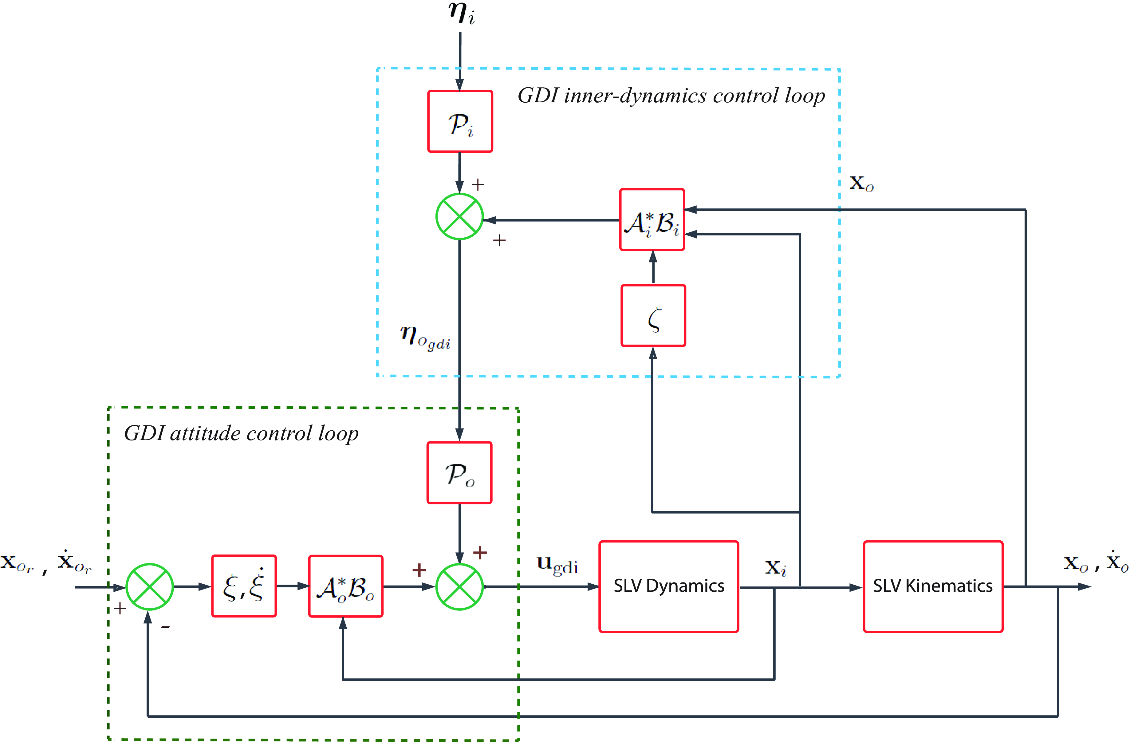
trajectories [Reference Ansari and Bajodah36], but not convergence, which necessitates robustifying the inner-dynamics loop performance. Actually robustifying the inner-dynamics loop performance is more important than robustifying the outer loop performance because the inner SLV dynamics given by Equation (26) is inherently dependent on the aerodynamic and inertia parameters of the SLV and on the external moments, which makes the closed loop inner dynamics of the SLV very susceptible to degradations in performance due to uncertainties in these parameters and to exogenous moment disturbances. The structure of the SGDI control system is illustrated in Fig. 2.
Baseline SGDI control system structure: detailed block diagrams of inner and outer GDI control loops and their interactions.

4.0 Performance robustification of SGDI control system
The baseline SGDI control system design guarantees boundedness of the attitude tracking error trajectories [Reference Ansari and Bajodah36]. However, dynamic scalings of the MPGIs
 $\mathcal{A}_o^ + $
and
 $\mathcal{A}_i^ + $
, unmodeled dynamics, aerodynamic and inertia parametric uncertainties, and exogenous disturbances hinder the convergence of
 ${{\textbf{e}}_o}$
and
 ${{\textbf{x}}_i}$
. Therefore, it is necessary to robustify the SGDI control system performance against these internal and external tracking performance retardation effects.
4.1 Outer SGDI control loop design robustification
The outer loop of the baseline SGDI control system is robustified by augmenting an additional control element in the loop. Define the functional
 ${S_o}$
as
 \begin{align}{S_o}\left( {{\xi _o},{{\dot \xi }_o},t} \right) = {\dot \xi _o} + {a_1}{\xi _o} + {a_2}\mathop \int \nolimits_{{t_0}}^t {\xi _o}d\tau, {{\;\;}}t \gt {t_0} \ge 0 \end{align}
where
 ${t_0}$
is an initial time instant. It is obvious from Equation (73) that convergence of both
 ${\xi _o}$
and
 ${\dot \xi _o}$
to zeros is equivalent to the convergence of
 ${S_o}$
to a finite number. The time derivative of
 ${S_o}$
is
 \begin{align}{\dot S_o} = {\ddot \xi _o} + {a_1}{\dot \xi _o} + {a_2}{\xi _o}, \end{align}
which can be written in the following form
 \begin{align}{\dot S_o} = {\mathcal{A}_o}{\textbf{u}} - {\mathcal{B}_o}. \end{align}
Let us now consider the following modified kinematical SVD
 \begin{align}{\dot S_o} + {a_3}{S_o} = 0,{{\;\;\;}}{a_3} \gt 0. \end{align}
The algebraic form of the modified kinematical SVD is
 \begin{align}{\mathcal{A}_o}{\textbf{u}} = {\mathcal{B}_o} - {a_3}{S_o}. \end{align}
The GDI attitude control law
 ${{\textbf{u}}_{\textrm{gdi}}}$
given by Equation (50) modifies accordingly to
 \begin{align} { {\textbf{u}}_{\textrm{rgdi}}} = \underbrace {\mathcal{A}_o^{\textrm{*}}\left( {{\mathcal{B}_o} - {a_3}{S_o}} \right)}_{ \in \mathcal{R}\left( {\mathcal{A}_o^T} \right)} + \underbrace {{\mathcal{P}_o}{\eta _o}}_{ \in \mathcal{N}\left( {{\mathcal{A}_o}} \right)}. \end{align}
With the inner loop design
 ${\eta _{{o_{\textrm{gdi}}}}}$
given by Equation (65), the SGDI attitude control law
 ${{\textbf{u}}_{{\textrm{s}}gdi}}$
given by Equation (69) modifies to
 \begin{align} { {\textbf{u}}_{\textrm{rgdi}}} & = \underbrace {\mathcal{A}_o^{\textrm{*}}\left( {{\mathcal{B}_o} - {a_3}{S_o}} \right)}_{ \in \mathcal{R}\left( {\mathcal{A}_o^T} \right)} + \underbrace {{\mathcal{P}_o}(\overbrace {\mathcal{A}_i^{\textrm{*}}{\mathcal{B}_i}}^{ \in \mathcal{R}\left( {\mathcal{A}_i^T} \right)} + \overbrace {{\mathcal{P}_i}{\eta _i}}^{ \in \mathcal{N}\left( {{\mathcal{A}_i}} \right)}}_{ \in \mathcal{N}\left( {{\mathcal{A}_o}} \right)} \nonumber\\[3pt]& = \underbrace {\mathcal{A}_o^{\textrm{*}}\left( {{\mathcal{B}_o} - {a_3}{S_o}} \right)}_{ \in \mathcal{R}\left( {\mathcal{A}_o^T} \right)} + \underbrace {\mathcal{A}_i^{\textrm{*}}{\mathcal{B}_i}}_{ \in \mathcal{R}\left( {\mathcal{A}_i^T} \right)} + \underbrace {{\mathcal{P}_o}\overbrace {{\mathcal{P}_i}{\eta _i}}^{ \in \mathcal{N}\left( {{\mathcal{A}_i}} \right)}}_{ \in \mathcal{N}\left( {{\mathcal{A}_o}} \right)}. \end{align}
The robust GDI control law
 ${{\textbf{u}}_{\textrm{rgdi}}}$
preserves the geometric structures of
 ${{\textbf{u}}_{\textrm{gdi}}}$
and
 ${{\textbf{u}}_{{\textrm{s}}gdi}}$
, i.e. the two vectors that compose
 ${{\textbf{u}}_{\textrm{rgdi}}}$
act on the two orthogonally complement subspaces
 $\mathcal{R}\left( {\mathcal{A}_o^T} \right)$
and
 $\mathcal{N}\left( {{\mathcal{A}_o}} \right)$
. The resulting closed loop inner dynamics is
 \begin{align}{{\dot{\textbf{x}}}_i} = {\textbf{A}} + B\left( {\mathcal{A}_o^{\textrm{*}}\left( {{\mathcal{B}_o} - {a_3}{S_o}} \right) + \mathcal{A}_i^{\textrm{*}}{\mathcal{B}_i} + {\mathcal{P}_o}{\mathcal{P}_i}{\eta _i}} \right). \end{align}
Setting the second term on the left-hand side of Equation (76) to zero reduces the differential and algebraic forms of the modified kinematical SVD to those given by Equations (37) and (42), respectively, and reduces the the expression of
 ${{\textbf{u}}_{\textrm{rgdi}}}$
given by Equation (79) to that of
 ${{\textbf{u}}_{{\textrm{s}}gdi}}$
given by Equation (69). The integral action modification on the kinematical SVD aims to improve tracking performance of the GDI attitude control loop by suppressing attitude tracking errors and perturbations.
4.2 Inner SGDI control loop design robustification
The null control vector design given by Equation (65) guarantees boundedness of the SLV’s angular velocity vector. However, the GDI design of the inner loop does not guarantee convergence of the angular velocity vector, mainly because of dynamic scaling of the MPGI
 $\mathcal{A}_i^ + $
. Moreover, the inner SLV dynamics given by Equation (26) is directly dependent on the aerodynamic and inertia parameters and on external moments. Therefore, the closed loop inner dynamics of the SLV is very susceptible to degradation in performance due to uncertainties in these parameters and due to exogenous disturbances.
Robust closed loop inner SGDI control system performance can be achieved in a manner that is similar to the manner followed in robustifying the closed loop outer stability of the SGDI control system, i.e. by augmenting an additional control element in the inner loop while preserving the structure of the SGDI control law. Define the functional
 ${S_i}$
as
 \begin{align}{S_i}\left( {{\zeta _i},t} \right) = {\zeta _i} + {b_1}\mathop \int \nolimits_{{t_0}}^t {\zeta _i}d\tau, {{\;\;}}t \gt {t_0} \ge 0 \end{align}
where
 ${t_0}$
is an initial time instant. It is obvious from Equation (81) that convergence of both
 ${\zeta _i}$
and
 ${\dot \zeta _i}$
to zeros is equivalent to convergence of
 ${S_i}$
to a finite constant. The time derivative of
 ${S_i}$
is
 \begin{align}{\dot S_{}} = {\dot \zeta _i} + {b_1}_i \end{align}
which can be written in the following form
 \begin{align}{\dot S_i} = {\mathcal{A}_i}{\eta _o} - {\mathcal{B}_i}. \end{align}
We now seek to enforce the following modified SVD on the SLV inner dynamics
 \begin{align}{\dot S_i} + {b_2}{S_i} = 0,{{\;\;\;}}{b_2} \gt 0. \end{align}
The algebraic form of the modified dynamical SVD is
 \begin{align}{\mathcal{A}_i}{\eta _{\textrm{o}}} = {\mathcal{B}_i} - {b_2}{S_i}. \end{align}
Performing dynamically scaled GDI on the modified SVD given by Equation (85) yields the following expression for the differential form of the robustified GDI outer null control vector
 ${\eta _{{o_{\textrm{rgdi}}}}}$
 \begin{align}{\eta _{{o_{\textrm{rgdi}}}}} = \mathcal{A}_i^{\textrm{*}}\left( {{\mathcal{B}_i} - {b_2}{S_i}} \right) + {\mathcal{P}_i}{\eta _i}. \end{align}
Substituting
 ${\eta _{{o_{\textrm{rgdi}}}}}$
in the expression of
 ${{\textbf{u}}_{\textrm{rgdi}}}$
given by Equation (78) yields the following robustified SGDI control vector of the SLV
 \begin{align} {{\textbf{u}}_{{\textrm{r}}sgdi}} & = \underbrace {\mathcal{A}_o^{\textrm{*}}\left( {{\mathcal{B}_o} - {a_3}{S_o}} \right)}_{ \in \mathcal{R}\left( {\mathcal{A}_o^T} \right)} + \underbrace {{\mathcal{P}_o}(\overbrace {\mathcal{A}_i^{\textrm{*}}\left( {{\mathcal{B}_i} - {b_2}{S_i}} \right)}^{ \in \mathcal{R}\left( {\mathcal{A}_i^T} \right)} + \overbrace {{\mathcal{P}_i}{\eta _i}}^{ \in \mathcal{N}\left( {{\mathcal{A}_i}} \right)}}_{ \in \mathcal{N}\left( {{\mathcal{A}_i}} \right)} \nonumber\\[3pt]& = \underbrace {\mathcal{A}_o^{\textrm{*}}\left( {{\mathcal{B}_o} - {a_3}{S_o}} \right)}_{ \in \mathcal{R}\left( {\mathcal{A}_o^T} \right)} + \underbrace {\mathcal{A}_i^{\textrm{*}}\left( {{\mathcal{B}_i} - {b_2}{S_i}} \right)}_{ \in \mathcal{R}\left( {\mathcal{A}_i^T} \right)} + \underbrace {{\mathcal{P}_o}\overbrace {{\mathcal{P}_i}{\eta _i}}^{ \in \mathcal{N}\left( {{\mathcal{A}_i}} \right)}}_{ \in \mathcal{N}\left( {{\mathcal{A}_o}} \right)}. \end{align}
The resulting closed loop inner dynamics is
 \begin{align}{{\dot{\textbf{x}}}_i} = {\textbf{A}} + B\left( {\mathcal{A}_o^{\textrm{*}}\left( {{\mathcal{B}_o} - {a_3}{S_o}} \right) + \mathcal{A}_i^{\textrm{*}}\left( {{\mathcal{B}_i} - {b_2}{S_i}} \right) + {\mathcal{P}_o}{\mathcal{P}_i}{\eta _i}} \right). \end{align}
Setting the second term on the left-hand side of Equation (84) to zero reduces the differential and algebraic forms of the modified inner SVD to those given by Equations (55) and (57), respectively, and reduces the the expression of
 ${{\textbf{u}}_{{\textrm{r}}sgdi}}$
given by Equation (87) to that of
 ${{\textbf{u}}_{\textrm{rgdi}}}$
given by Equation (79). Augmenting an integral element of
 $\zeta $
in the GDI inner-dynamics control loop works to suppress the perturbations in the angular velocity vector
 ${{\textbf{x}}_i}$
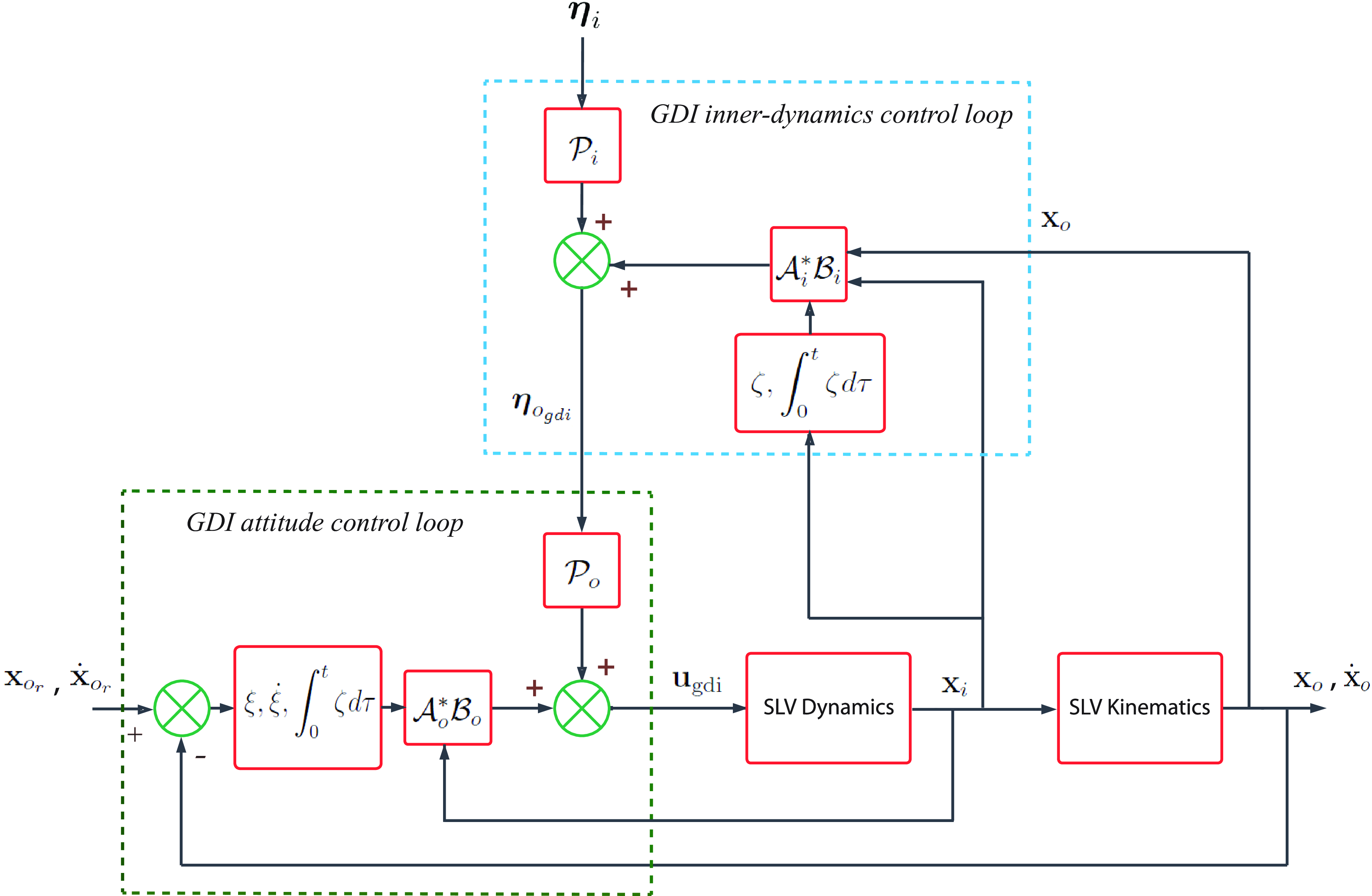
. The performance-robustified SGDI control system is illustrated in Fig. 3.
Robust SGDI control system structure: detailed block diagrams of robustified inner and outer GDI control loops and their interactions.

5.0 Optimal reference trajectory generation, reshaping and rational energy management
This section describes the procedure that is followed in this paper to optimise the SLV reference trajectory according to the ascent flight mission requirements and constraints. The section also highlights the need to reshape the open loop optimal reference trajectory and the strategy that is followed to fulfill that purpose. Finally, the rational energy management is described.
5.1 Optimal reference trajectory generation
The SLV under consideration is capable of injecting a payload of
 $500$
kg into a
 $300$
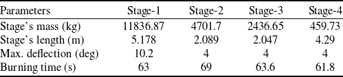
km sun synchronous low Earth orbit (LEO). The SLV has four stages as shown in Table 1 and was utilised in Refs. (Reference Ansari11–Reference Ansari and Alam13) for the purpose of SLV trajectory generation, optimisation, and control for different objectives and under different constraints.
Data of a four-stage SLV

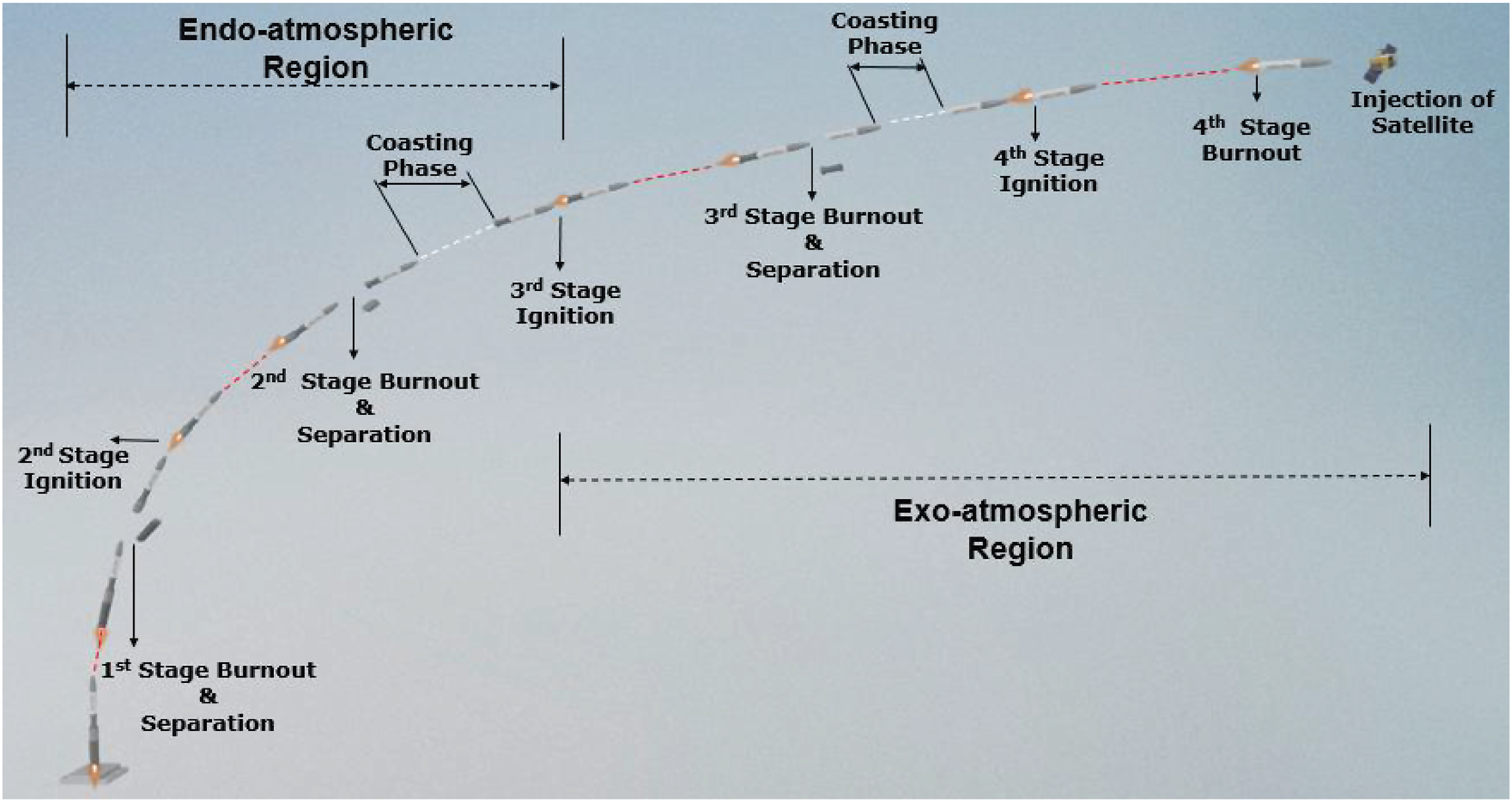
The ascent flight of the considered SLV is composed of four burning phases, during which the SLV manoeuvers are performed by means of four engine motors. Also, the SLV experiences two coasting phases of
 $100$
and
 $85$
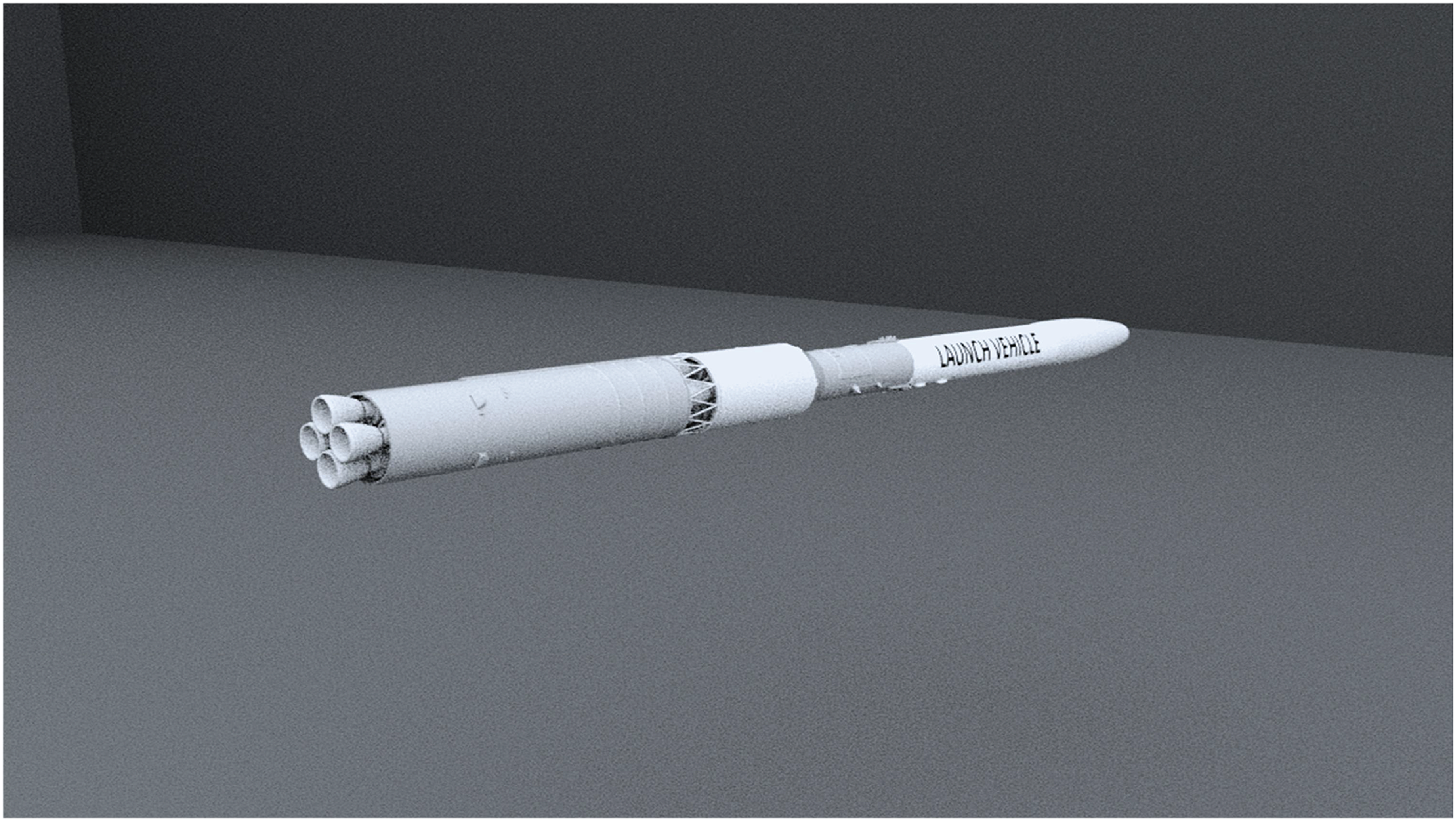
s after the second and the third stage burnouts, respectively. The ascent flight coasting phases are crucial for the SLV to attain desired orbital altitude. A schematic of the four-stage SLV’s structural design is given in Fig. 4, showing stage configuration, engine motors arrangement and overall shape of the SLV. Fig. 5 depicts the operational trajectory of the present SLV ascent flight experiment and the corresponding sequence of events. The figure outlines the burning phases of each stage and the coasting phases that follow, and how these stages function sequentially during the launch process.
Four-stage SLV structural design.

Four-stage SLV operational trajectory: ascent flight sequence of events and stage functionality.

Generating an optimal reference trajectory for the ascent flight phase is crucial to plan for the energy that is required to fulfill the SLV mission, and to avoid excessive thrust requirements and control actuators limitations. Optimising the reference trajectory aims also to restrict aerodynamic heating on the SLV’s body and to maintain its structural loading within the design limits. To generate the optimal flight trajectory, the following point mass model of the SLV is used [Reference Xiao35]
 \begin{align} {{\dot{\textbf{V}}}_l} & = \frac{{{L_{lb}}}}{m}\left[ {\begin{array}{c}{T - Q{S_{{\textrm{ref}}}}{C_D}}\\[3pt] {Q{S_{{\textrm{ref}}}}{C_{{L_\alpha }}}}\\[3pt] 0\end{array}} \right] + {L_{le}}{{\textbf{g}}_e} \\[-10pt] \nonumber\end{align}
 \begin{align} \dot h & = \sqrt {{x_e}^2 + {y_e}^2} - {R_L} \\[-10pt] \nonumber\end{align}
 \begin{align} \vartheta & = {\textrm{ta}}{{\textrm{n}}^{ - 1}}\left\{ {\frac{{{V_{yl}}}}{{{V_{xl}}}}} \right\} \\[-10pt] \nonumber\end{align}
 \begin{align} \theta & = {\alpha _{\textrm{prog}}} + \vartheta \\[6pt] \nonumber\end{align}
where
 ${\alpha _{\textrm{prog}}}$
is the optimal angle-of-attack profile required to achieve desired orbital parameters, and
 ${R_L}$
is the local radius of the earth given by
 \begin{align}{R_L} = {R_E}\frac{1 - f}{{\sqrt {1 - f\left( {2 - f} \right){\textrm{co}}{{\textrm{s}}^2}\lambda } }}. \end{align}
In the above expression of
 ${R_L}$
,
 ${R_E} = 6378.140$
km is the Earth’s equatorial radius,
 $f = 0.00335281$
is the Earth’s oblateness factor, and
 $\lambda $
is the latitude above which the point mass is located. The optimal SLV trajectory is determined by constrained optimisation of the angle-of-attack profile. The involved optimisation constraints are mainly on the maximum value of the angle-of-attack and the dynamic pressure, maximum axial and lateral inertial acceleration loadings on the body of the SLV, in addition to the orbital parameters of the mission, namely terminal velocity and altitude, and time duration of the ascent flight phase.
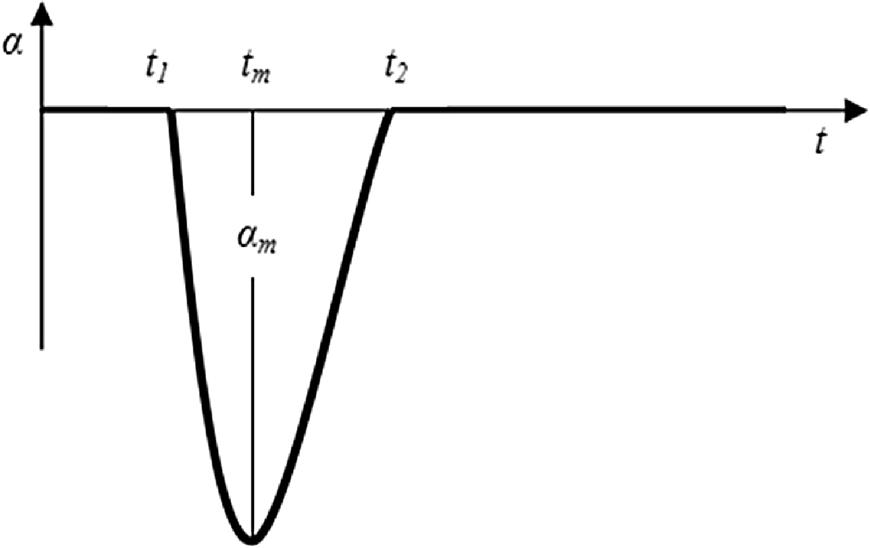
The design methodology that was followed to obtain the optimal SLV trajectory is based on global genetic algorithms (GA) open loop optimal guidance [Reference Ansari11, Reference Ansari and Alam12]. The GA algorithm strives to find the optimal angle-of-attack profile parameters, namely the time
 ${t_1}$
to start the pitch-over phase, the maximum value of the angle-of-attack
 ${\alpha _m}$
and its occurrence time
 ${t_m}$
, and the time
 ${t_2}$
at which the angle-of-attack returns back to zero as depicted in Fig. 6.
Designing the angle-of-attack profile: parameters
 ${t_1}$
,
 ${t_m}$
,
 ${t_2}$
, and
 ${\alpha _m}$
are optimised using genetic algorithms to achieve desired orbital parameters.

In addition to producing the optimal path to the orbit and the corresponding velocity profile, the optimal trajectory design produces the desired profiles of the pitch and yaw angles. The reference roll attitude angle is maintained at the zero value throughout the ascent flight mission. The SLV’s trajectory optimisation is performed by minimising the following objective function
 \begin{align}O = {(h - {h_{{\textrm{ref}}}})^2} + {(V - {V_{{\textrm{ref}}}})^2} + {(\vartheta_l - {{\vartheta_l} _{{\textrm{ref}}}})^2}, \end{align}
where
 ${h_{{\textrm{ref}}}} = 300$
km,
 ${V_{{\textrm{ref}}}} = 7800$
m/s, and
 ${{\vartheta_l} _{{\textrm{ref}}}} = 0$
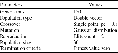
deg are the corresponding reference values. Values of the parameters used in the GA implementation that yield fast convergence speed and and high solution quality are shown in Table 2.
GA parameters

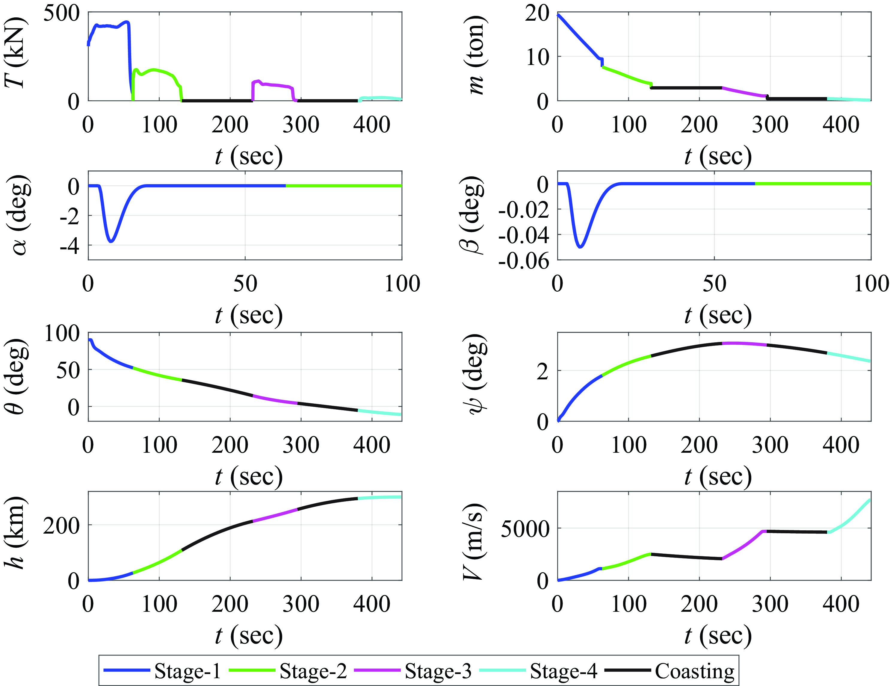
The obtained profiles of the variables that correspond to the achieved open loop optimal ascent flight phase trajectory are shown in Fig. 7.
Optimised SLV open-loop reference trajectories: optimal parameters for different stages of the ascent flight phase versus time.

5.2 Reference trajectory reshaping and rational energy management
The mathematical model that is usually used for the purpose of SLV trajectory generation is a simple idealised point mass model. Obtaining the point mass model requires performing several approximations and assumptions on the original six DOFs SLV model, at the cost of lowering the SLV model fidelity. Moreover, the open loop approach that is used to generate the optimal trajectory assumes undisturbed nominal environmental conditions along the SLV ascent flight trajectory.
Hence, tracking the open loop optimal trajectory leads to unsatisfactory terminal flight conditions in the presence of un-modelled SLV dynamics and external disturbances, i.e. it causes the actual values of the orbital parameters to deviate from the desired terminal constraint values. In particular, the final SLV altitude will be different from the desired orbital altitude, the orbital injection velocity will be different from the orbital velocity, and the orbital injection angle will be different from the desired zero flight path angle, resulting in terminal dispersions from the desired orbit.
Therefore, a realistic SLV trajectory generation design must involve a continuous in-flight updating of the open loop optimal trajectory such that the desired terminal conditions of the ascent flight phase are achieved while satisfying the mission and vehicle constraints.
To accomplish that goal, a hybrid GA/Fuzzy logic-type closed-loop guidance loop was used to reshape the generated optimal trajectory of the considered SLV and to update the reference roll and yaw commands [Reference Ansari11, Reference Ansari and Alam12]. The optimal steering logic of the guidance law enhances the autonomy of the SLV by steering it closer to the pre-computed optimised reference trajectory while satisfying the mission and the vehicle constraints, in addition to satisfying the desired terminal altitude and flight path angle conditions under the influence of point mass modeling uncertainties and environmental disturbances.
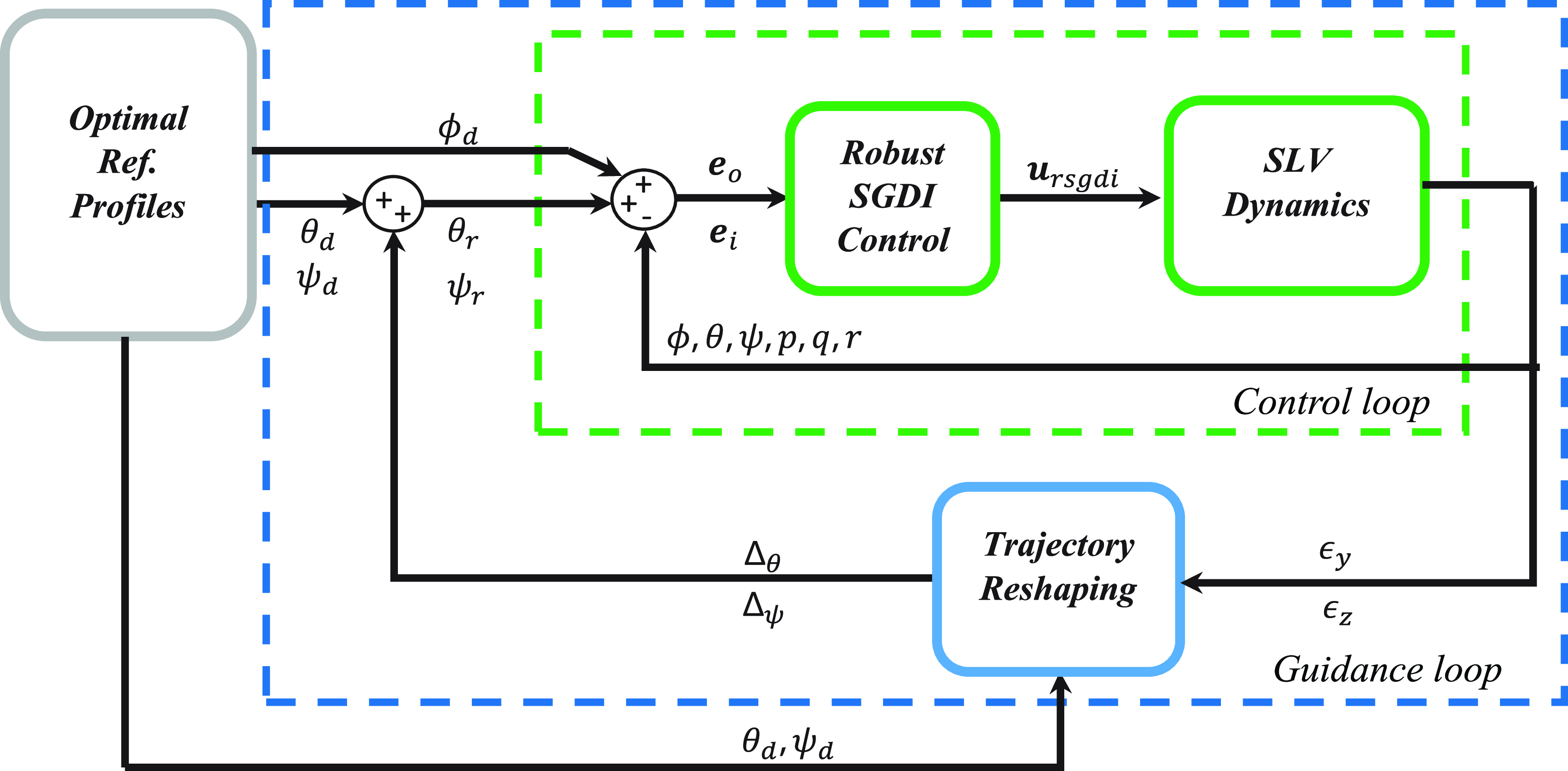
Additionally, the ‘rational energy management method’ for velocity control was also suggested in Ref. (Reference Ansari11) through activations of engine shutoff commands during the third stage powered phase to correct for the SLV velocity such that the achieved orbital injection velocity is equal to the required terminal velocity constraint despite the presence of inherent perturbations and environmental disturbances. The general structure of the closed-loop guidance and control loops is depicted in Fig. 8.
SLV closed-loop guidance and robust SGDI control system: reference attitude trajectories are reshaped by the guidance loop and are fed into the robust SGDI control system.

The optimal reference trajectory design provides the open loop attitude commands
 ${\phi _d} = 0$
,
 ${\theta _d}$
, and
 ${\psi _d}$
to the guidance (outer) loop. The trajectory reshaping mechanism is implemented to generate the closed loop reference attitude commands
 ${\theta _r}$
and
 ${\psi _r}$
given by
 \begin{align}{\theta _r} = {\theta _d} + {\Delta_\theta },{{\;\;\;\;}}{\psi _r} = {\psi _d} + {\Delta_\psi } \end{align}
where
 ${\Delta_\theta }$
and
 ${\Delta_\psi }$
are computed as
 \begin{align}{\Delta_\theta } = {k_\theta }{\epsilon _y},{{\;\;\;\;}}{\Delta_\psi } = {k_\psi }{\epsilon _z},. \end{align}
In (96), the normal dispersion
 ${\epsilon _y}$
is the deviation of the SLV position trajectory from its nominal path in the
 ${x_l}{y_l}$
plane of the LRF, i.e.
 ${\epsilon _y} = h - {h_{{\textrm{r}}ef}}$
. The lateral dispersion
 ${\epsilon _z}$
is the deviation of the SLV position trajectory from the nominal path in the transverse (normal to the
 ${x_l}{y_l}$
plane) direction, and
 ${k_\theta }$
and
 ${k_\psi }$
are positive gain constants. The aim of this paper is to design the robust SGDI control system to track the closed loop reference attitude trajectories
 ${\theta _r}$
and
 ${\psi _r}$
while maintaining
 ${\phi _d}$
at zero.
6.0 Numerical simulations
The robust SGDI SLV closed loop control system simulations are carried out next with reference trajectory reshaping. To emphasise the advantage of robustifying the baseline SGDI control system via the integral term, closed loop simulations are carried out with and without the integral robustifying term for the purpose of comparing the performance of the two control laws. A comparative study follows the proposed robust SGDI control system and a classical SMC trajectory tracking control system. Finally, a statistical dispersion analysis of the robust SGDI control system is performed by extensive Monte Carlo simulations.
6.1 Robust SGDI SLV control simulations with trajectory reshaping
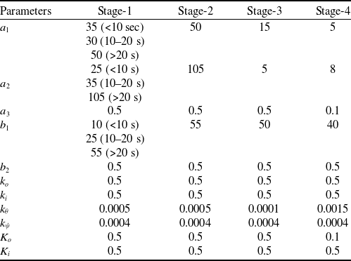
Numerical simulations of closed loop-controlled attitude manoeuvers along with trajectory reshaping are performed on a six DOFs SLV simulator to demonstrate the performance of robust SGDI control. The parameter values of reshaped closed loop guidance and robust SGDI control are summarised in Table 3 for different time intervals of the ascent flight.
Numerical values of guidance and control parameters

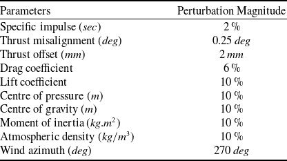
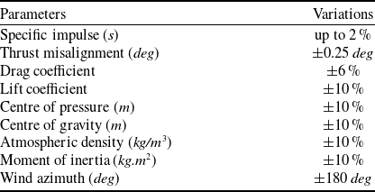
To demonstrate the robustness attributes of SGDI control, parametric uncertainties and external perturbations are included intentionally in the mathematical model of the multi-stage SLV simulator while keeping these parameters at their nominal values in the SGDI control loops. The perturbed parameters and their perturbation percentages are listed in Table 4.
Parametric uncertainties and disturbances

The aim of the robust SGDI control system is to track the reshaped attitude angle profiles of
 $\phi $
,
 $\theta $
and
 $\psi $
by generating the control deflection commands
 ${u_\phi }$
,
 ${u_\theta }$
, and
 ${u_\psi }$
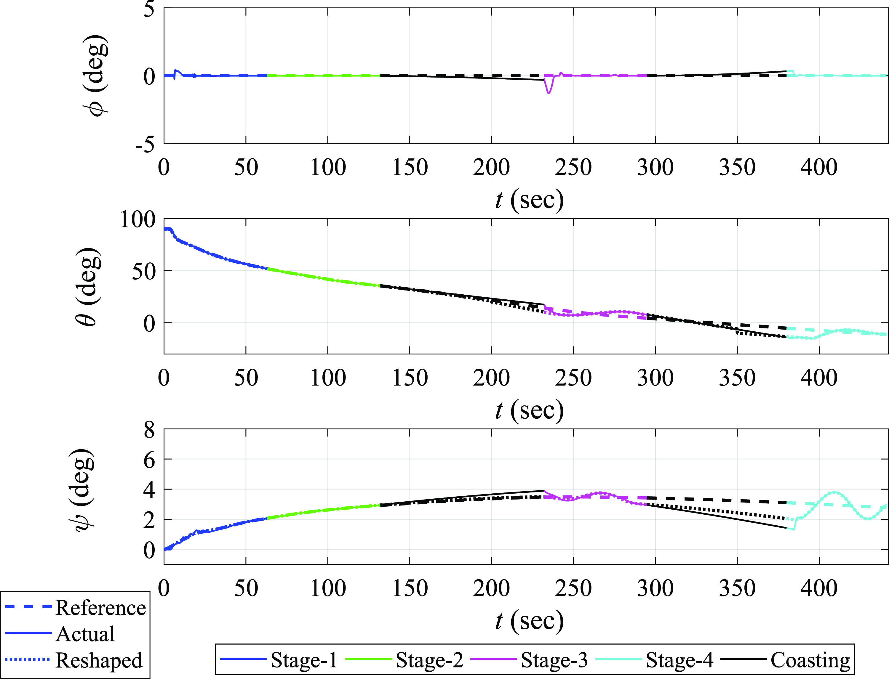
. The attitude tracking history is shown in Fig. 9. Tracking is lost during the coasting phases due to the absence of thrust. However, the robust SGDI control system exhibits fast convergence towards the desired (reshaped) attitude profiles once thrust is restored. Very small oscillations are experienced in the
 $\theta $
and
 $\psi $
reshaped reference attitude angles profiles and the corresponding actual controlled values during the final phase (
 ${4^{th}}$
stage) of flight because the inertia of the SLV continues to cause lateral and normal dispersions from the desired orbit as the guidance system is working to reshape the attitude reference profiles in order to eliminate these dispersals. The robust SGDI control system, however, provides excellent tracking of the reshaped attitude trajectories during the final phase.
Robust SGDI control system performance: time histories of reference, reshaped and actual attitude angles trajectories under parametric uncertainties and wind disturbance.

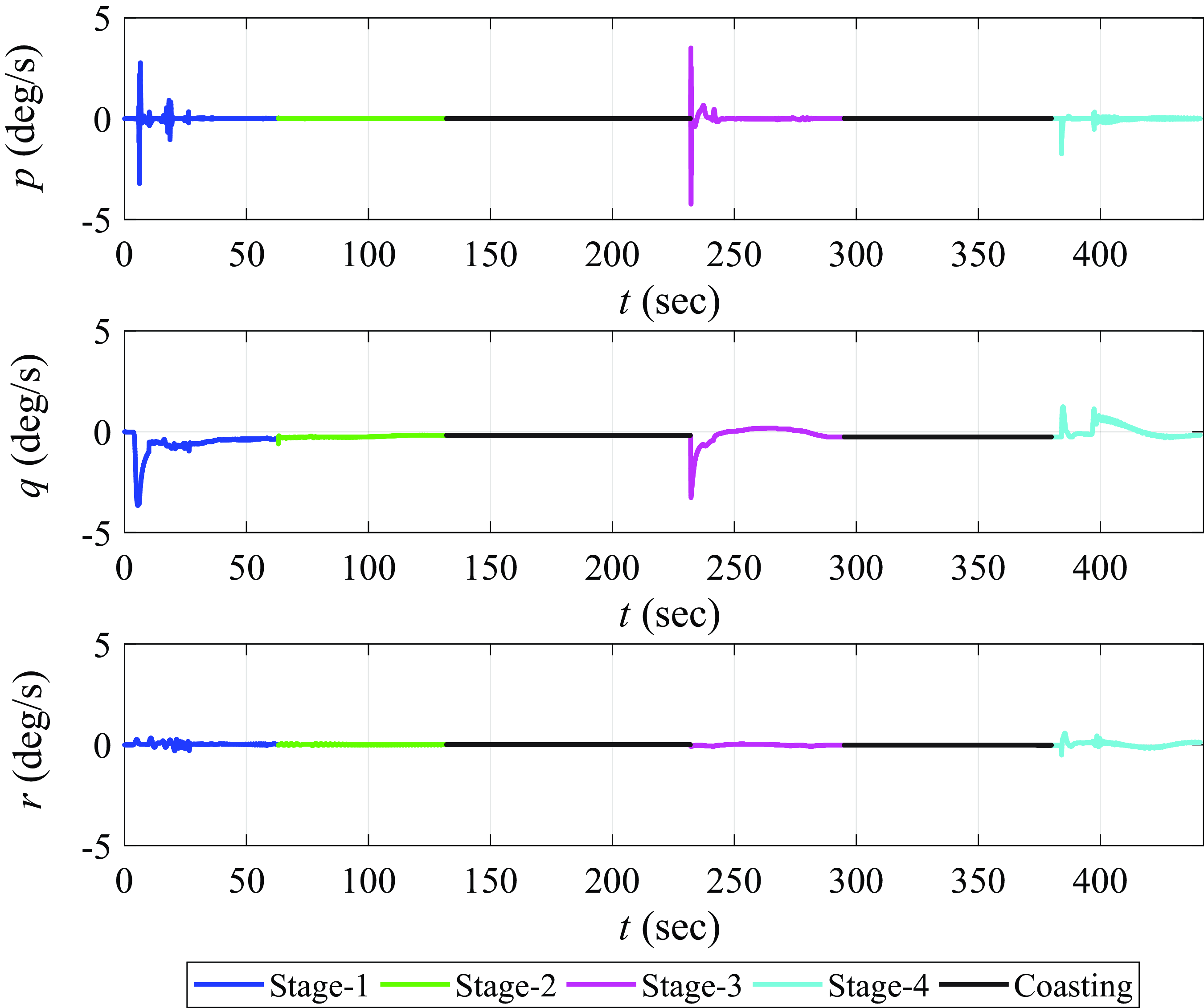
The time history of the SLV body angular velocity components is shown in Fig. 10. The robust SGDI control system limits the angular velocity level and fluctuations throughout the flight trajectory even in the region of high dynamic pressure, despite the inherent instability of the SLV and the presence of parametric uncertainties and wind disturbances.
Robust SGDI control system performance: time histories of body angular velocity components under parametric uncertainties and wind disturbance.

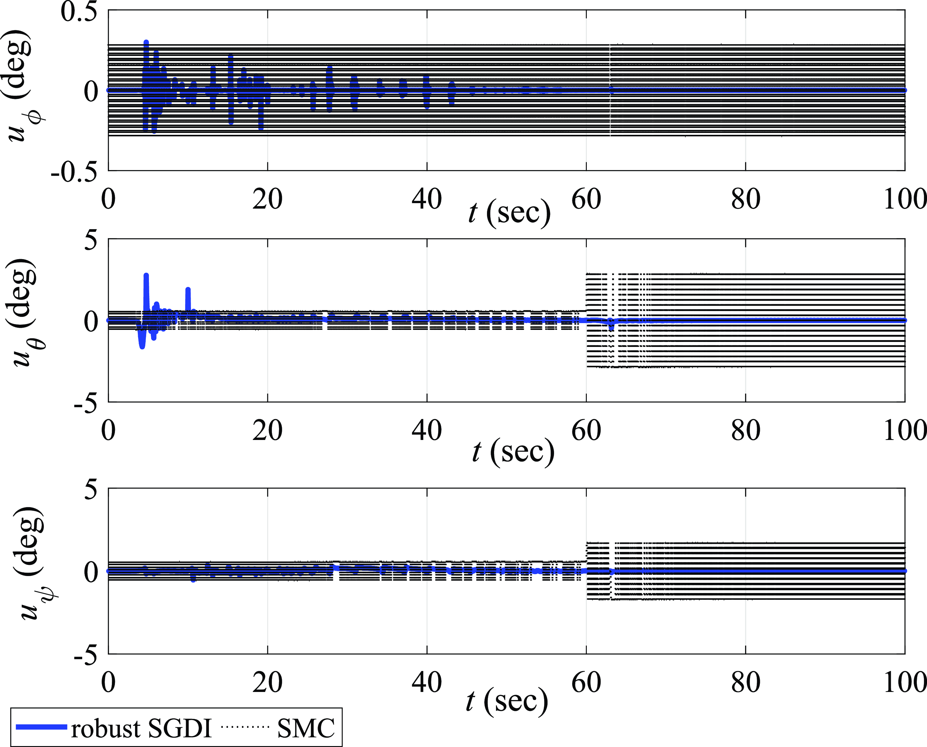
The time history of the control surfaces deflection commands
 ${u_\phi }$
,
 ${u_\theta }$
, and
 ${u_\psi }$
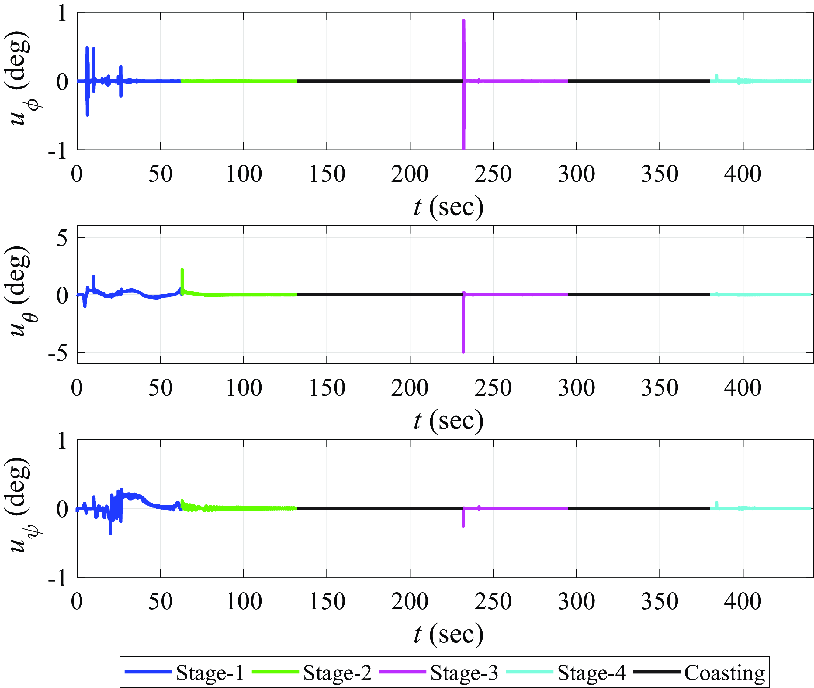
is shown in Fig. 11. The control surfaces deflections that are required to perform the attitude manoeuvers vary within a permitted range of
 $ \pm 5deg$
, and none is experiencing undesired chattering. The control surfaces deflections are obviously zeros during the two coasting phases.
Robust SGDI control system performance: time histories of control surface deflections required to perform the attitude manoeuvers.

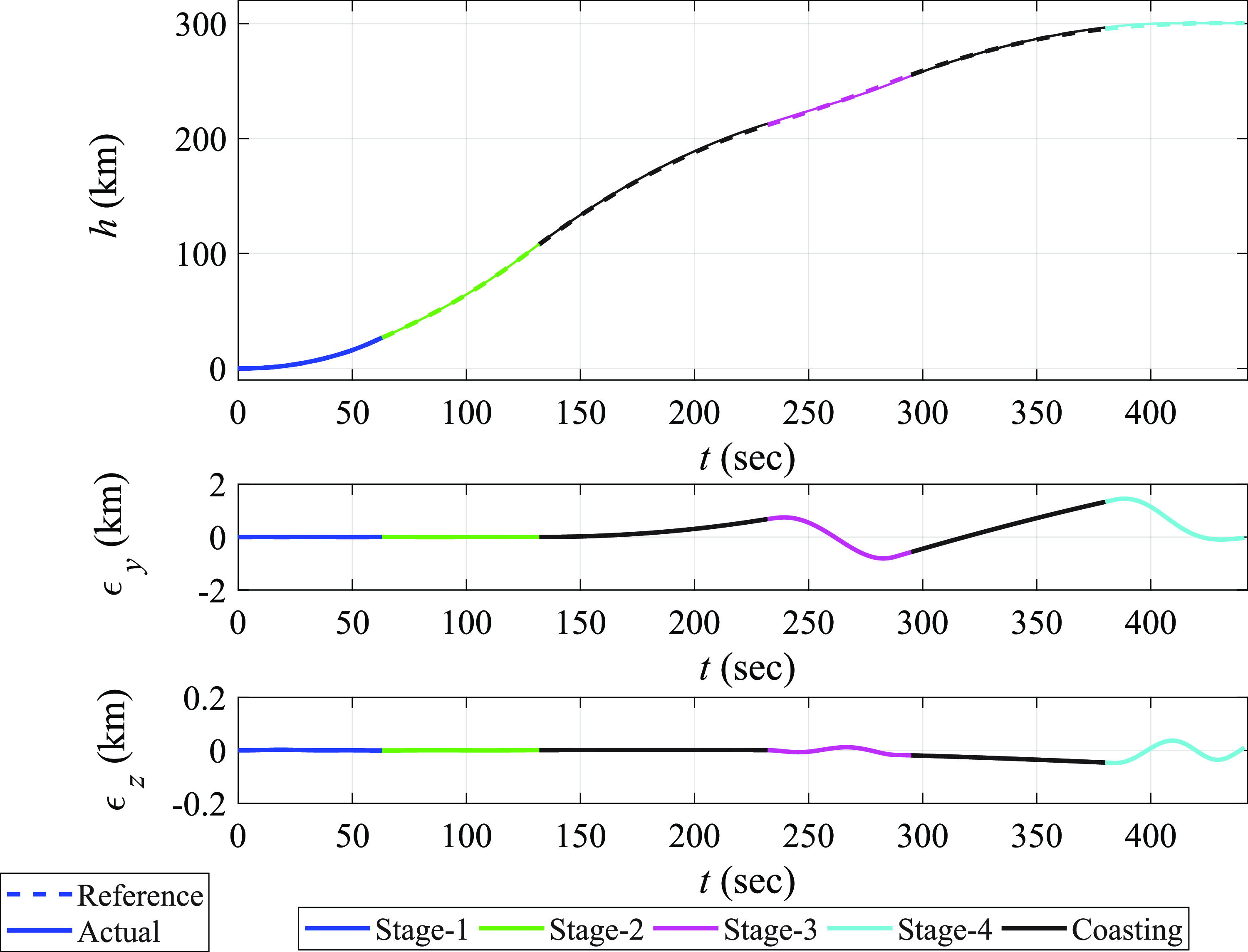
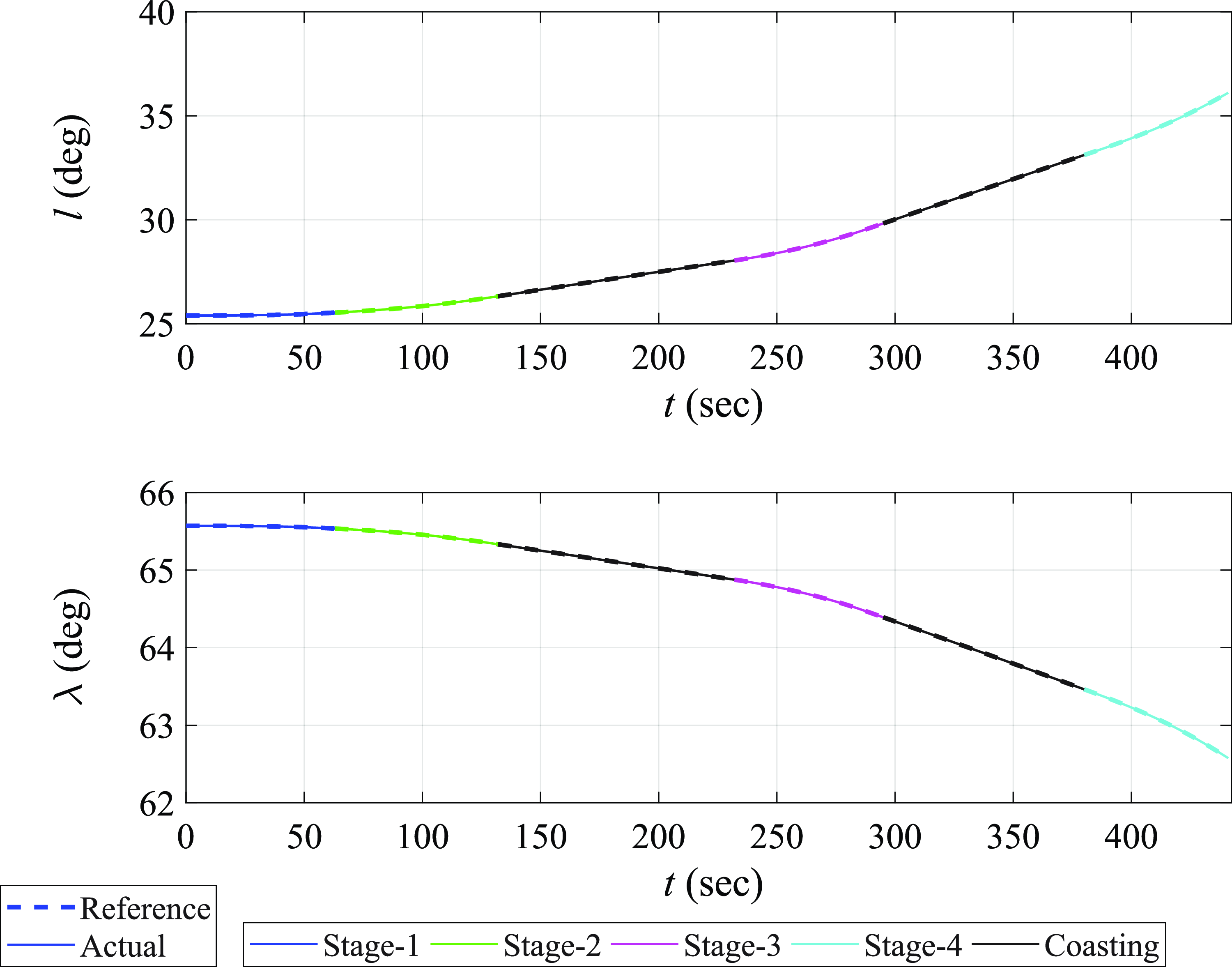
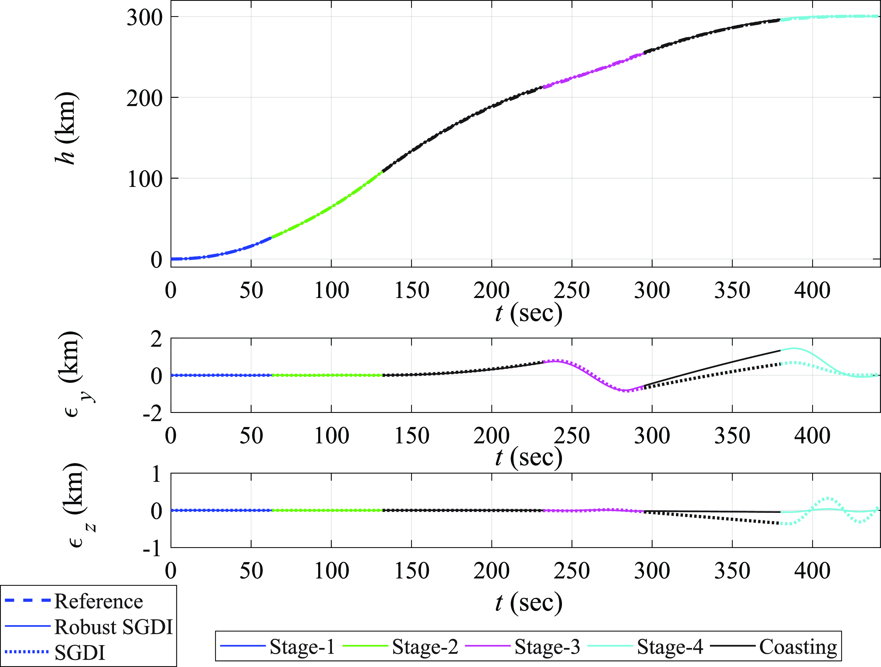
The ascent trajectory tracking performance of the SLV is depicted in Fig. 12. The SLV tracks the reference altitude profile closely as the reshaped attitude guidance commands are followed by the robust SGDI control system until the SLV achieves the desired orbit and afterwards. The positional dispersions variables
 ${\epsilon _y}$
and
 ${\epsilon _z}$
are also shown in Fig. 12. Finally, the time histories of actual and desired latitude and longitude profiles are shown in Fig. 13.
Robust SGDI control system performance: reference and actual altitude over time, highlighting positional dispersions.

Robust SGDI control system performance: time histories of actual and desired latitude and longitude profiles throughout the ascent flight stages.

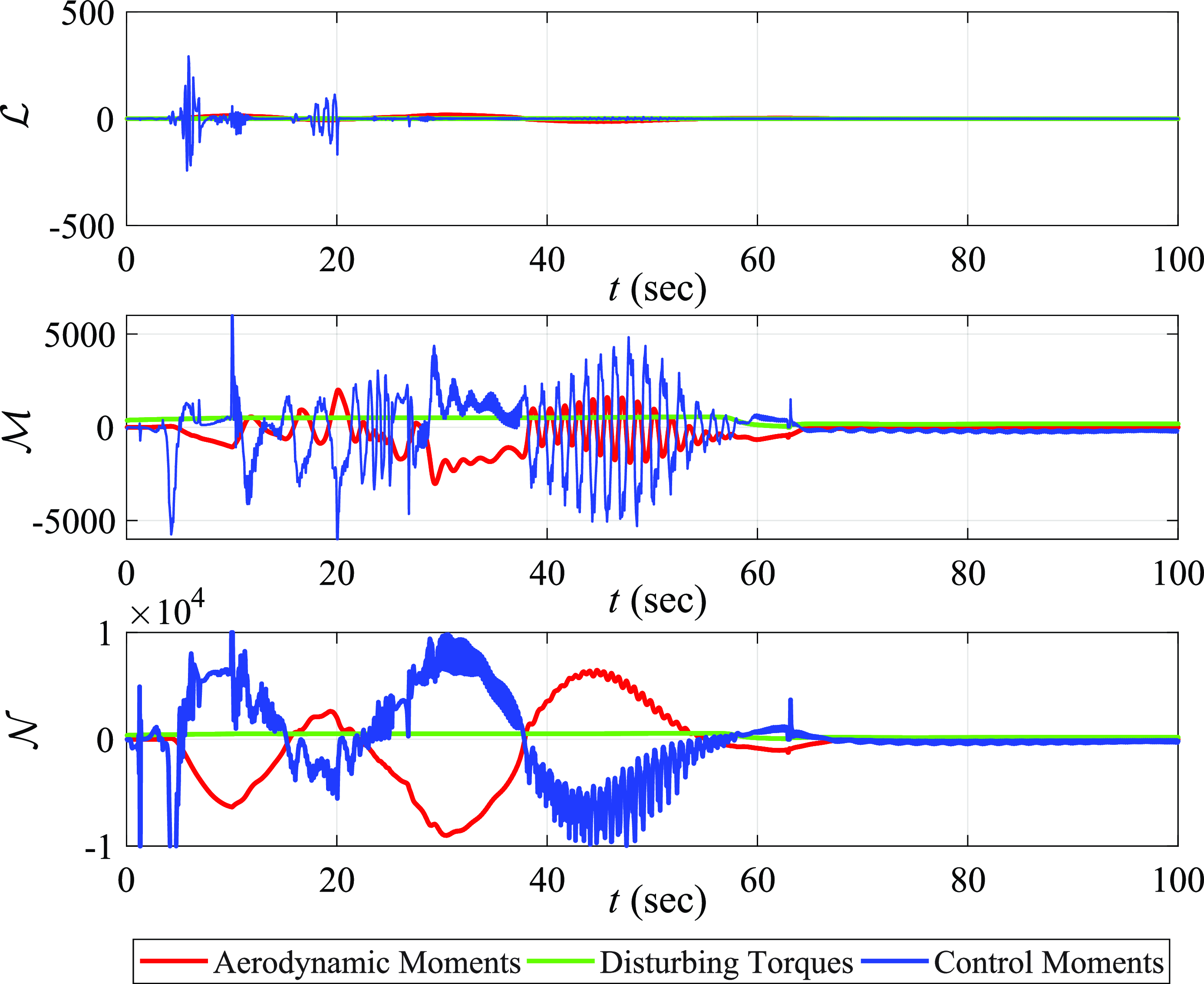
Figure 14 compares control, aerodynamic and disturbing torques due to thrust offset and misalignment throughout the ascent flight phases. Although disturbance torques are relatively small, aerodynamic torques are significant during the high aerodynamic pressure endo-atmospheric phase. The control moments effectively counterbalance these torques, maintaining stable and high-performance ascent flight.
Robust SGDI control system performance: time histories of control moments in comparison with aerodynamic and disturbance torques, showcasing the control moments counter effects.

6.2 Impact of SGDI control system robustification
In order to emphasise on the significance of robustifying the SGDI control law via the integral terms
 ${S_o}$
and
 ${S_i}$
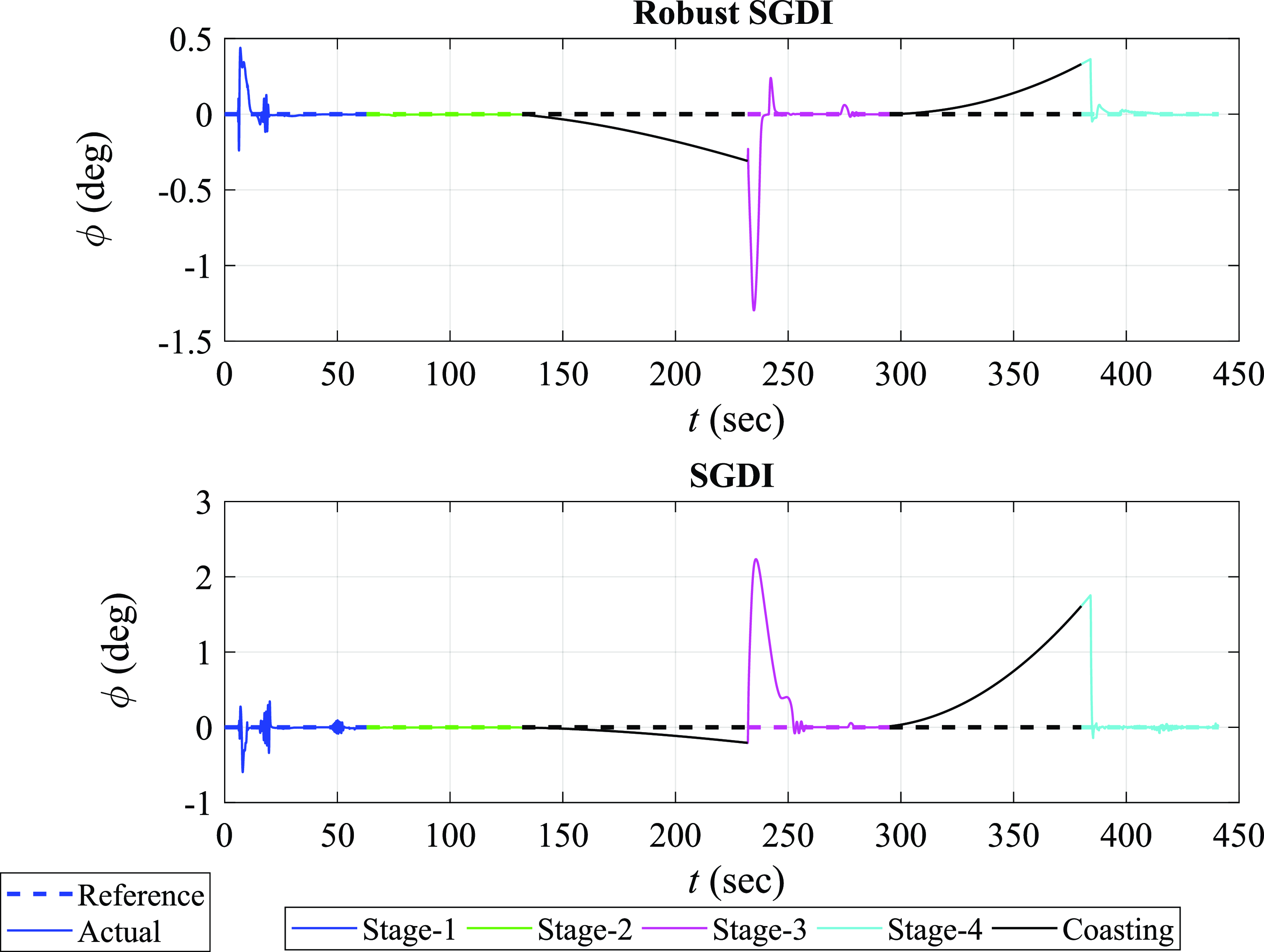
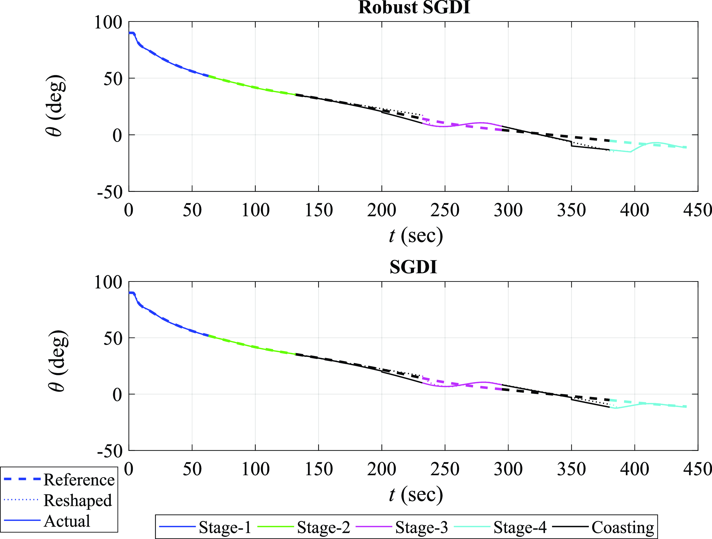
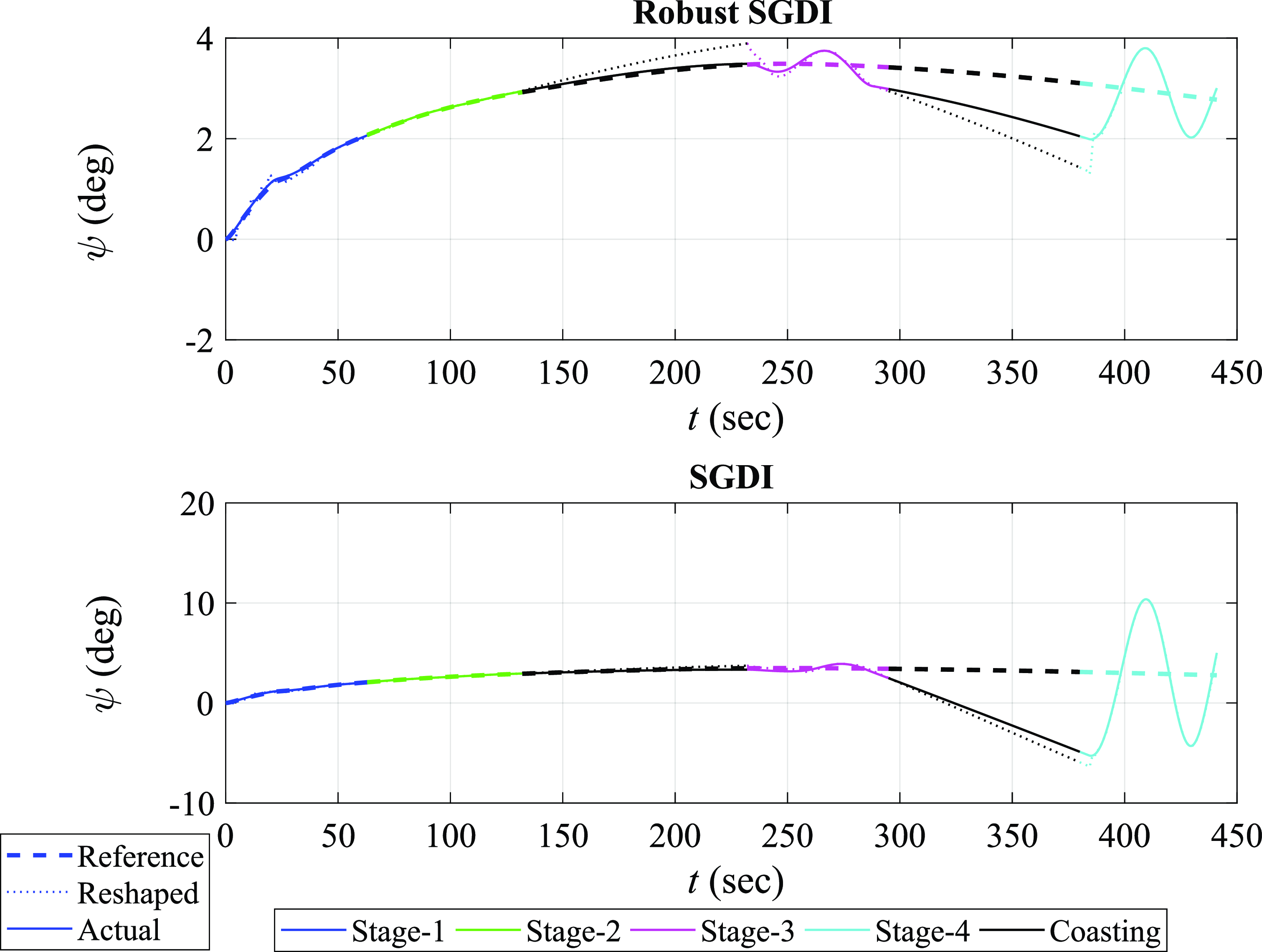
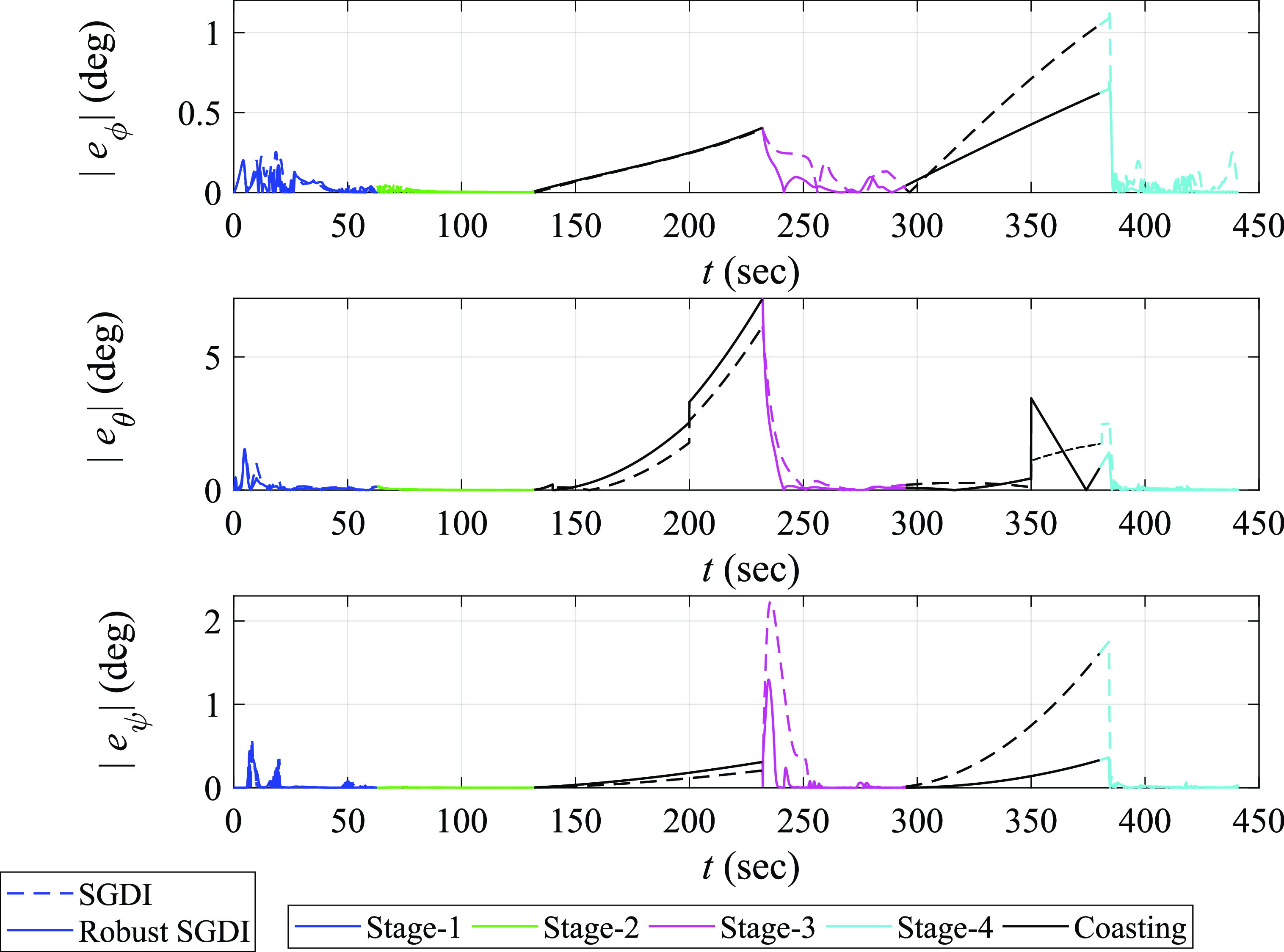
, a series of comparative simulations were conducted by implementing robust SGDI control and by deliberately omitting the robustifying integral terms. The attitude variables tracking behaviours for both cases are shown in Figs 15, 16 and 17. Also, Fig. 18 shows the magnitudes of residual errors across the three attitude channels for both cases. The simulation-driven depictions highlight the distinctive impact and contribution of the SGDI robustifying terms in enhancing the overall SLV’s attitude tracking performance.
SGDI vs. robust SGDI: roll angle behaviour throughout ascent flight stages.

SGDI vs. robust SGDI: pitch angle behaviour throughout ascent flight stages.

SGDI vs. robust SGDI: yaw angle behaviour throughout ascent flight stages.

SGDI vs. robust SGDI: residual errors magnitudes across attitude channels throughout ascent flight stages.

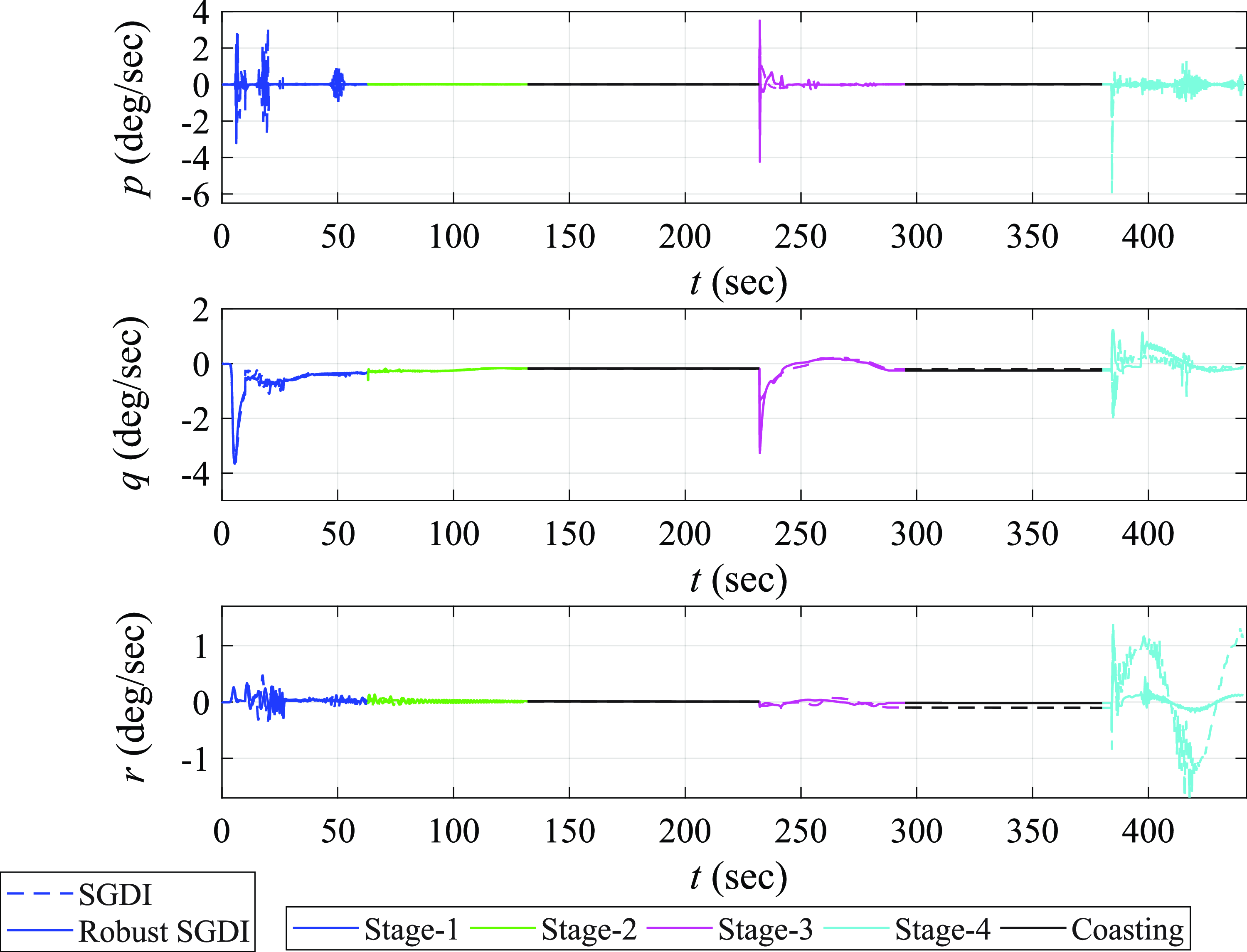
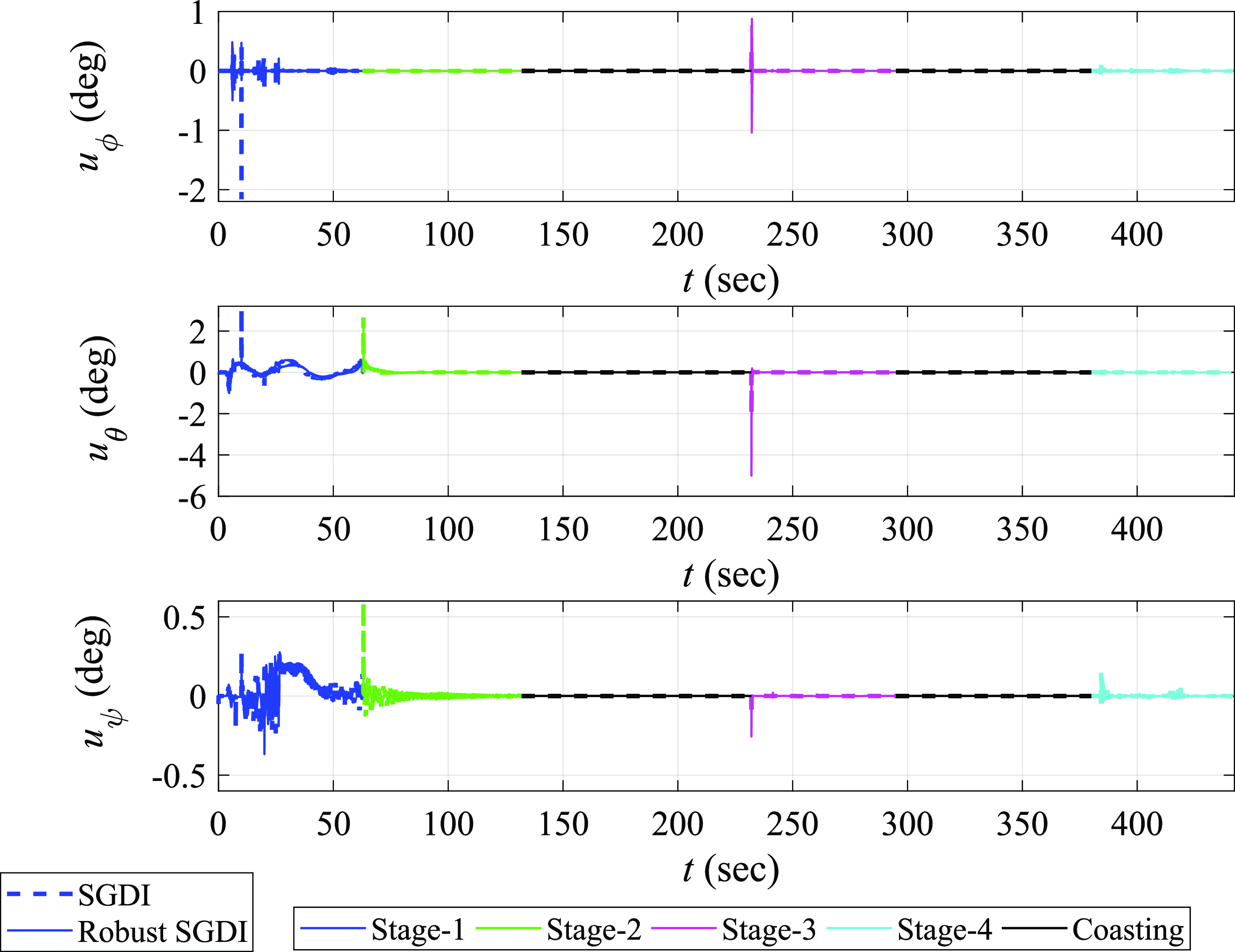
The inclusion of the robustifying SGDI integral terms lead to an expedited convergence of attitude angles towards the reference attitude profiles, particularly following the coasting phases. The accelerated convergence is a clear advantage of employing robust SGDI control in improving stability robustness of SGDI control. Furthermore, it is evident that the attitude errors during the controlled powered phase are significantly reduced in the presence of the robustifying terms. The reduction of attitude tracking discrepancies substantiates the positive influence of the integral terms on performance robustness of SGDI control. Similarly, Figs 19 and 20 show the robust SGDI terms effect on the SLV’s body angular velocity and control surfaces deflections.
SGDI vs. robust SGDI: body angular velocity components throughout ascent flight stages.

SGDI vs. robust SGDI: control surfaces deflections throughout ascent flight stages.

However the outer guidance loop overshadow the impact of the robust SGDI terms in the context of ascent flight trajectory. The trajectories as shown in Fig. 21 appear to follow a similar path regardless of the presence of the robustifying terms.
SGDI vs. robust SGDI: SLV’s altitude throughout ascent flight stages.

6.3 Comparison of robust SGDI and classical SMC
The robust SGDI control system performance is assessed by comparing it with the performance of a classical SMC system, focusing on the initial pitch-over phase, which constitute approximately
 $100$
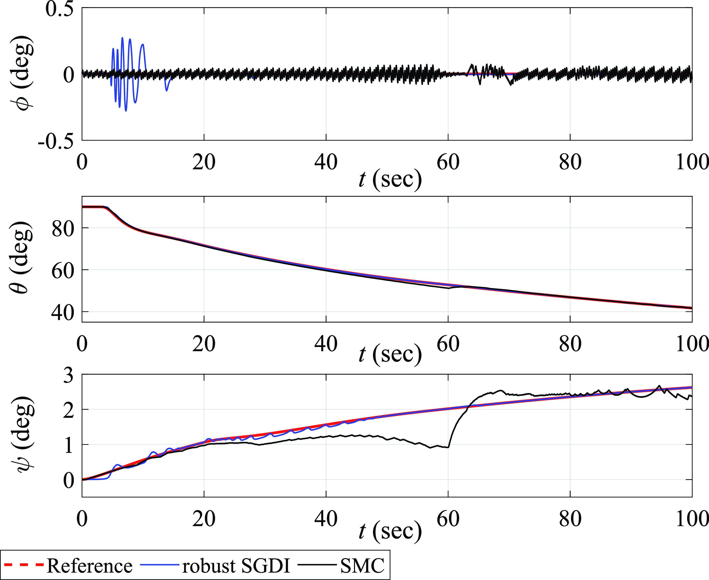
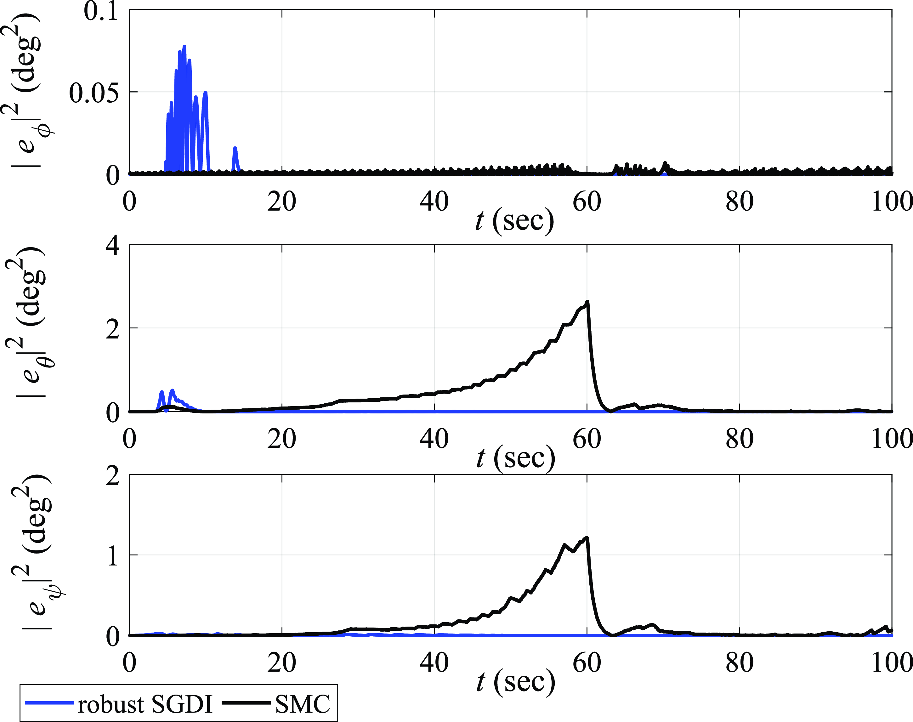
s of the ascent flight trajectory. The comparison focuses on attitude tracking performance of both control systems during this critical phase. Time histories of attitude tracking and the corresponding square errors are shown in Figs 22 and 23, respectively.
Robust SGDI vs. SMC: attitude tracking performance, focusing on the initial pitch-over phase of the ascent flight trajectory.

Robust SGDI vs. SMC: squared attitude tracking errors.

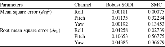
With the exception of the initial
 $15$
s for the roll channel, robust SGDI control consistently demonstrates a superior performance in minimising tracking errors when compared to SMC. Table 5 provides mean square error (MSE) and root mean square error (RMSE) comparisons for robust SGDI and SMC control across roll, pitch and yaw channels. It has been observed that robust SGDI consistently outperforms SMC in terms of MSE and RMSE, except for roll channel.
Attitude error comparison for robust SGDI and SMC

Similarly, the comparison of control deflections between robust SGDI control and SMC is shown in Fig. 24. The control commands generated by SMC are impacted by the chattering phenomenon, characterised by rapid and undesirable switching behaviour of the control signal. This phenomenon can severely impede the performance and stability of the controlled system.
Robust SGDI vs. SMC: control surface deflections, revealing the SMC chattering phenomenon.

Table 6 provides comparisons of the control efforts required by the robust SGDI and SMC designs for attitude tracking along roll, pitch and yaw axes. The control effort for a given channel is defined as the area under the corresponding plot in Fig. 24. By examining these values, the high-performance characteristics and practicality of implementation of the robust SGDI control approach become clear.
Comparison of control efforts for SGDI and SMC

6.4 Statistical dispersion analysis of robust SGDI control
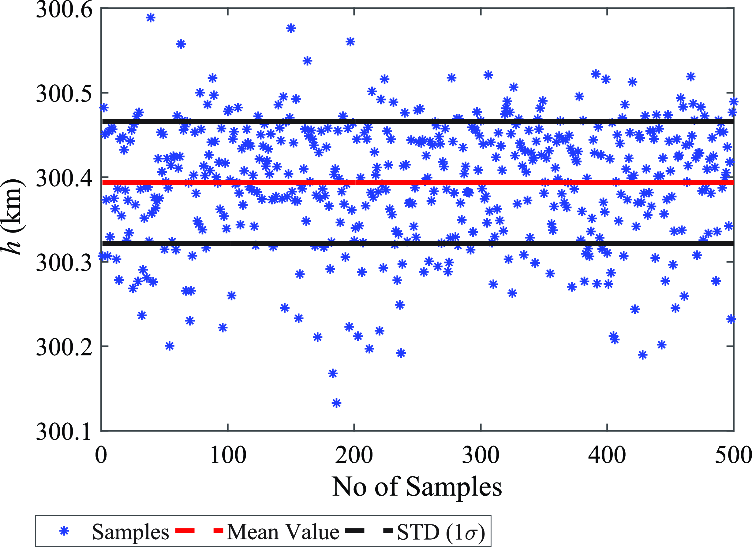
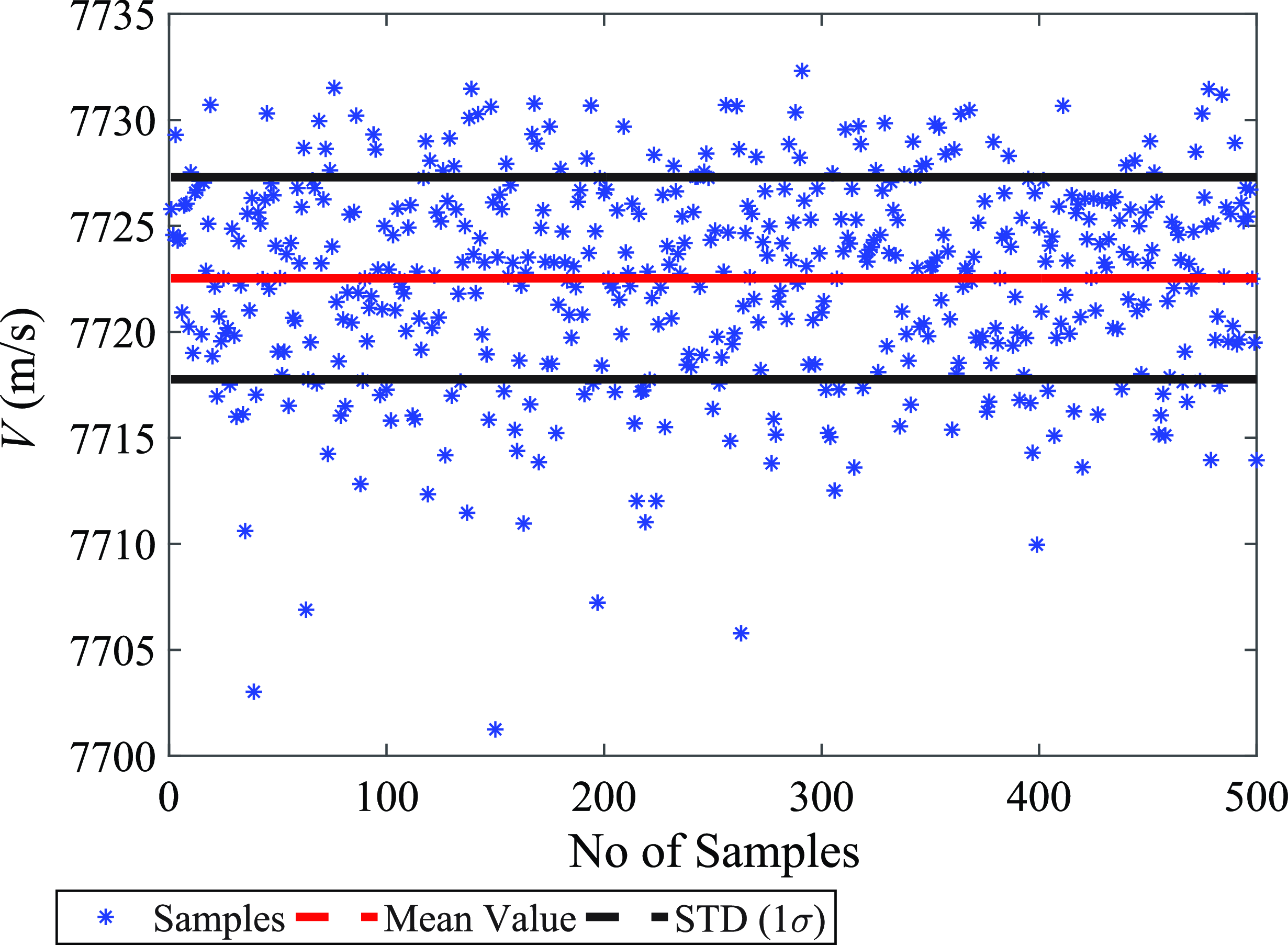
The present statistical analysis aims to investigate robustness of SGDI closed loop control with trajectory reshaping when the SLV intervenes with random variations in its dynamic parameters and under the influence of vital environmental turbulence. To accomplish this analysis, Monte Carlo simulations were conducted by considering various combinations of variations in a set of parameters that affect the SLV performance.
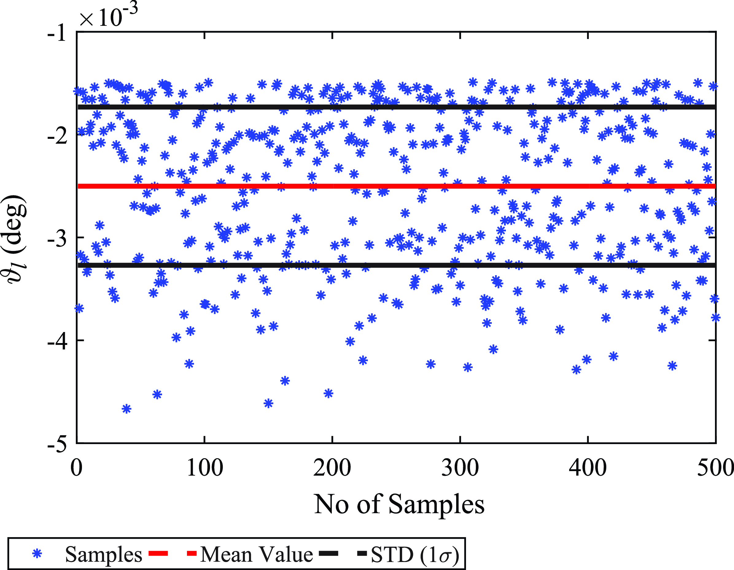
The parameters that are chosen to perform the Monte Carlo simulations are the specific impulse, mass flow rate, drag and lift coefficients, atmospheric density and wind azimuth. A number of
 $500$
cases were simulated by considering an array of random variations in the chosen parameters. The variations comply with Gaussian distributions with predefined tolerances and bounds in a specified envelope as shown in Table 7. The results acquired from Monte Carlo simulations are depicted by plotting the achieved orbital parameters against number of samples in Figs 25, 26, and 27.
Parametric variations and disturbances

Monte Carlo simulations: achieved orbital altitude versus Monte Carlo simulation samples.

Monte Carlo simulations: achieved orbital velocity versus Monte Carlo simulation samples.

Monte Carlo simulations: achieved local flight path angle at orbital injection versus Monte Carlo simulation samples.

The obtained dispersion data of the orbital parameters from their terminal state values using Monte Carlo simulation are depicted in Table 8, including the nominal and maximum values, the mean value and 1
 $\sigma $
standard deviation. The achieved orbital altitude, velocity and flight path angle are within reasonable ranges and are well distributed against parametric uncertainties and environmental perturbations.
Monte-Carlo analysis

7.0 Conclusion
The paper presents a novel SGDI-based control system design for multistage SLV attitude tracking. The GDI control methodology is applied in a successive manner to design the outer and inner loops of the proposed SGDI control system, taking advantage of the favourable geometric features of GDI control. Additionally, robustifying integral control elements are augmented in the outer and inner loops of the SGDI control system to improve the SLV tracking performance against dynamic scaling of the MPGI, modeling and parametric uncertainties and exogenous disturbances. Numerical simulations are conducted on a six DOFs simulator of a four-stage SLV. The optimised reference flight trajectories are generated using genetic algorithms by employing the data of the SLV. The numerical simulations exhibit satisfactory tracking performance of the proposed robust SGDI control system by closely tracking the SLV pre-determined optimised path to achieve the required orbital parameters. The proposed robust SGDI-based control system efficiently and effectively meets the requirements of attitude control system design for multistage SLVs.
Acknowledgements
This project was funded by the Deanship of Scientific Research (DSR), King Abdulaziz University, Jeddah, Saudi Arabia, under grant no. (KEP-1-135-42). The authors, therefore, acknowledge with thanks DSR technical and financial support. This paper is part of the research work the second author did during his PhD studies at King Abdulaziz University.
Data availability
Data sharing not applicable to this article as no datasets were generated or analysed during the current study.
Competing interests
The authors declare none.