Introduction
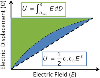
Capacitors with high power and high energy have been actively pursued in recent decades because of their critical role in modern electronic and electrical applications, such as high-frequency inverters, insulated-gate bipolar transistor snubbers, power factor correction, and pulsed power generation. Reference Sarjeant, Zirnheld, MacDougall, Bowers, Clark, Clelland, Price, Hudis, Kohlberg, McDuff, McNab, Parler, Prymak and Nalwa1,Reference Wang and Zhu2 Electrostatic capacitors offer the highest power density, lowest loss, and highest operating voltage among various types of capacitors, including electrolytic capacitors and supercapacitors. However, the low energy densities of these capacitors (<2 J cm–3) fall short of the ever-increasing demands for compact, reliable, and efficient electrical power systems. It is imperative to develop novel technologies that can significantly increase the energy density of electrostatic capacitors. In principle, energy density (U e) in a dielectric is determined by the applied electric field (E) and the electric displacement (D) as Reference Dang, Yuan, Yao and Liao3
 $$U_e = \int_{D_{\max } }^0 {E\,dD} ,$$
shown by the blue-colored area in Figure 1 . The electric displacement (D) is related to the polarization (P) by Reference Dang, Yuan, Yao and Liao3
 $$D = P + {\varepsilon _r}{\varepsilon _0}E,$$
Schematic illustration of the electric displacement (D) and discharge energy density (U, colored area) with applied electric field (E). For nonlinear dielectrics, the discharge energy density is determined from the area in green, whereas for linear dielectrics, the discharge energy density is determined from the triangular area (blue + green). Note: ε0 = 8.85 × 10⁻¹² F m–1 is the vacuum permittivity, and εr is the relative dielectric permittivity of the dielectric.

Hence, high polarization leads to high displacement. For linear dielectrics,
 ${U_e}{ = ^1}{/_2}{\varepsilon _r}{\varepsilon _0}{E_B}^2,$
where
 ${\varepsilon _0}$
= 8.85 × 10⁻¹² F m–1 is the vacuum permittivity, and εr and E
B are the relative dielectric permittivity and breakdown strength, respectively, of the dielectric.
Given its quadratic dependence on E B, U e is largely determined by the breakdown strength of the dielectric. Polymers, such as biaxially oriented polypropylene, are thus the primary dielectric of choice in dielectric capacitors because of their high breakdown strengths (>700 V m–1), low dielectric losses (<0.02%), and “graceful failure” at breakdown (i.e., an open circuit is formed). Reference Reed and Cichanowski4–Reference Chen, Shen, Zhang and Zhang10 The major drawback of polymer dielectrics is their low εr values (usually <3) and, consequently, small electrical displacements (D), which result in low energy densities (<2 J cm–3) in practical capacitor devices despite the ultrahigh breakdown strengths of dielectric films.
To address these issues, the nanocomposite approach has been intensively explored, whereby polymeric and inorganic phases are integrated facilely. The rationale behind the nanocomposite approach lies in the potential of combining the high breakdown strength and low dielectric loss of the polymer with the high dielectric constant of a ceramic filler, leading to a high energy density. Reference Nan11 One major benefit of this approach is that the large interfaces in the nanocomposites could promote interfacial exchange coupling through a dipolar interface layer and lead to enhanced polarization and polarizability in the polymer matrix close to the interface. In addition, given the nanometer size of the ceramic particles, it is possible to reduce the thickness of the polymer matrix film to the nanoscale. The interfaces between the ceramic nanoparticles and polymer also provide traps for mobile electrons that mitigate the multiplication of free electrons through collisions (avalanche effects), further enhancing the already high breakdown strength of polymer. Reference Li12,Reference Bune, Fridkin, Ducharme, Blinov, Palto, Sorokin, Yudin and Zlatkin13
Although this approach is straightforward at first sight, it can be complicated by a number of factors, including the filler–matrix interfaces and anisotropy of the fillers, which can largely determine the dielectric behavior of these nanocomposites. Moreover, a highly inhomogeneous electric field is induced by nanoparticles with high dielectric constants, which generates local hot spots of increased field concentration and reduces the effective breakdown strength of the composites. Reference Peruani, Solovey, Irurzun, Mola, Marzocca and Vicente14–Reference Li, Huang and Zhang16 Innovative strategies need to be developed to balance the seemingly contradictory demands of enhancing the dielectric constant while maintaining a high dielectric strength, and to fully explore the promises and potential of nanocomposites.
Theoretical considerations
Interface and interfacial polarization
In polymer nanocomposite dielectrics, the interface between the ceramic nanoparticles and the polymer matrix is defined as the range over which the permittivity changes from the value of the ceramic nanoparticles to that of the polymer matrix. For instance, for a 10-nm-diameter nanoparticle with a 5.0-nm-thick interface, the interfacial volume fraction exceeds 300%. Given their high volume fraction in the composites, interfaces are the dominant feature of nanocomposite dielectrics. Reference Lewis17
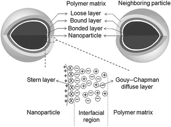
Two characteristics of interfaces are critical in describing their dielectric responses, namely, how they are chemically formed and how the charges are distributed across the interfacial regions. To describe the formation of interfaces, Tanaka et al. Reference Tanaka, Kozako, Fuse and Ohki18 proposed a multilayer core model for a spherical inorganic filler embedded in a polymer matrix, as shown in Figure 2 . The first layer is the bonded layer, which corresponds to a transition layer that is tightly bonded by ionic, covalent, or hydrogen bonds or van der Waals forces, to both the nanoparticle and the polymer. The second layer (the bound layer) is an interfacial region consisting of a layer of polymer chains strongly bound to or interacting with the bonded layer and the surface of the nanoparticle. The third layer is a region loosely coupling and interacting with the second layer, in which the chain conformation, chain mobility, and even free volume or crystallinity differ from those of the polymer matrix.
Multicore model for interfaces between inorganic nanoparticles and a polymer matrix in a polymer nanocomposite. The model consists of a bonded layer, a bound layer, and a loose layer. As the nanoparticle is positively charged, an electrical double layer (comprising the Stern and Gouy–Chapman diffusion layers) forms in the interfacial region and overlaps the three layers of the model. Adapted with permission from Reference 3.

In addition to the chemical bonds, the morphologies of the interface layers are also strongly affected by the charge distribution across the interfacial regions. Within these regions, Coulombic forces (long range), van der Waals forces (moderate range), and electrostatic forces (short range) are involved and can significantly alter the interface layers. When subjected to an electric field, the interfaces in a polymer composite can become charged. The charged interface is generally described in terms of three charged layers that invariably form and determine the dielectric characteristics of the interface, as shown in Figure 2. On the nanoparticle side, a double layer associated with surface states is induced by immobile charged impurities, trapped carriers, and mobile electrons and holes in the nanoparticle. After the nanoparticle becomes charged, the surrounding polymer responds by establishing a screening countercharge confronting the charge on the nanoparticles.
The mobile ions in the polymer will migrate to establish a diffuse electrical double layer (the so-called Stern–Helmholtz double layer) around the nanoparticle, which is of molecular thickness and can have a high charge density. The nanoparticle side of the Stern–Helmholtz double layer consists of adsorbed ions or dipoles, whereas the polymer side of this layer (also called the outer Helmholtz plane [OHP]) is determined by the nearby ions. Extending beyond the OHP into the polymer is the so-called Gouy–Chapman diffusion layer. In this region, the mobile charges are distributed in such a way that the countercharges with opposite polarity are diffused outward from the OHP to the Debye shielding length, decaying exponentially with distance according to the Born approximation. Filled with mobile charge, the Gouy–Chapman diffusion layer could play a dominant role in determining the dielectric response of polymer composite dielectrics. Reference Lewis19 By considering the charge density and electric potential within the interface layers, Reference O’Konski20–Reference Lopez-Pamies, Goudarzi, Meddeb and Ounaies22 the core–shell model provides plausible explanations for the extreme enhancement in the dielectric response of polymer composites. However, its basic assumption is that the electric field remains unaltered outside the core–shell-type nanoparticles, which obviously is not the case in real polymer composites.
Distribution of local electric field
In polymer nanocomposites, the local electric field close to the nanoparticle fillers can be significantly altered. When nanoparticles with high dielectric constants are introduced, increased polarization—and hence a higher charge density at the surface of the nanoparticles—is induced. This polarization is then countered by charges (mobile ions or dipoles induced by the polar groups in the polymer chain) in the polymer matrix. Within the double layer, the electrical field is significantly enhanced, becoming higher than the field in either the nanoparticles or the polymer matrix. Reference Lewis19
In theoretical studies within the framework of self-consistent effective media theory, Reference Li and Ducharme23,Reference Kim, Doss, Tillotson, Hotchkiss, Pan, Marder, Li, Calame and Perry24 the core–shell model is employed by considering the interfaces in polymer composites as an interfacial phase with finite thickness. The dielectric nanocomposite can then be considered as a three-phase material, consisting of a polymer matrix (phase 1), an interfacial phase (phase 2) of finite thickness, and nanoparticle fillers (phase 3). For this three-phase composite, the effective permittivity κ* can be expressed as
 $$\kappa * = {\kappa _1} + {f_2}\left( {{\kappa _2} - {\kappa _1}} \right){a_2} + {f_3}\left( {{\kappa _3} - {\kappa _1}} \right){a_3},$$
where f r and a r are the volume fraction and electric-field concentration factor, respectively, of phase r. The average electric field in phase r is then related to the electric field applied at the boundary (E 0) as
 $$\left\langle {{E_r}} \right\rangle = {a_r}{E_0}.$$
The effective medium approximation provides a reasonable estimate of a r (r = 2, 3) as Reference Hori and Nemat-Nasser25–Reference Li27
 $${a_r} = 1 - S{\left[ {{{\left( {{\kappa _r} - \kappa * } \right)}^{ - 1}}\kappa * + s} \right]^{ - 1}},$$
where s is the depolarization factor, which is 1/3 for spherical particles. The field concentration factor for the polymer matrix can then be determined from the normalization condition as
 $$\sum\limits_{r = 1}^3 {{f_r}{a_r} = 1} \,.$$
By taking into account the statistical fluctuation of the field throughout the polymer composite, the apparent breakdown strength of the polymer composite (E B) can be predicted more accurately as
 $${E_0}\left( {{a_1} + \sqrt {{1 \over {{f_1}}}{{\partial \kappa * } \over {\partial {\kappa _1}}}} - a_1^2} \right) \ge {E_B}$$
The implication of these modeling results is that special measures should be taken to mitigate electric-field concentration in order not to cause a serious reduction in the dielectric breakdown strength of polymer composites.
Core–shell-structured polymer nanocomposites
The most common approach to modulating the filler–polymer interface is surface modification of the nanoparticles. To form robust interface layers on the surface of nanoparticles and suppress dielectric losses, covalent bonding between the surface modifiers and the nanoparticles is highly desirable. Phosphonic acid Reference Kim, Doss, Tillotson, Hotchkiss, Pan, Marder, Li, Calame and Perry24,Reference Rao and Wong28–Reference Kim, Jones, Hotchkiss, Haddock, Kippelen, Marder and Perry31 and hydroxyl groups Reference Zhou, Zha, Cui, Fan, Yuan and Dang32,Reference Liu, Zhai, Wang, Xue and Zhang33 have been anchored on the surface of BaTiO3 and Ba0.6Sr0.4TiO3 nanoparticles to induce covalent bonding between the nanoparticles and the polymer matrix. Dopamine, a bioinspired building block with aromatic and amido groups, has recently been explored as a compatibilizer between inorganic nanoparticles and polymer matrixes. Reference Lee, Dellatore, Miller and Messersmith34–Reference Song, Shen, Hu, Lin, Li and Nan37 The surface layer not only affords a homogeneous dispersion of nanoparticles, but also suppresses the remnant polarization usually associated with surface charges in the loose interface between the nanoparticle and polymer.
Another strategy for modulating the filler–polymer interface is to graft the host polymer chains directly onto the nanoparticles without using small-molecule surface modifiers. After the corresponding monomers have been grafted to the surface of BaTiO3 nanoparticles, subsequent atom-transfer radical polymerization Reference Xie, Huang, Wu and Jiang38 or surface-initiated reversible addition−fragmentation chain-transfer polymerization Reference Yang, Huang, Huang, Xie and Jiang39 yields a dense polymer surface layer on the BaTiO3 nanoparticles to form core–shell-structured BaTiO3/polymer composites. In polymer composites filled with poly(heptadecafluorodecyl acrylate)-coated BaTiO3 nanoparticles, the dielectric loss is only 0.02 (at 100 Hz), which is even lower than that of a poly(vinylidene fluoride-co-hexafluoropropylene) (P[VDF-HFP]) matrix (0.06), even when the volume fraction of BaTiO3 nanoparticles is as high as 50 vol%. Reference Yang, Huang, Huang, Xie and Jiang39
The charge distribution in the interfacial regions can also be modulated by this core–shell approach. In a polystyrene (PS) nanocomposite comprising core–shell BaTiO3 nanoparticles with diblock copolymer shielding layers, Reference Jung, Kang, Yang, Won and Kim40 polystyrene-block-poly(styrene-co-vinylbenzylchloride) (PS-b-PSVBC) self-assembles and forms a dense shell layer on the BaTiO3 nanoparticles once the chloromethyl groups in PSVBC are converted to ammonium groups by treatment with triethylamine. Within the shell layer, the nonpolar polystyrene blocks of the diblock copolymer form the outer layer, with the polar ammonium-containing blocks preferentially residing in the inner layer and bonding closely with the BaTiO3 nanoparticles. The surface of the BaTiO3 nanoparticles can then be charged with ammonium groups in the inner layer, which contributes to high polarization in the composites. This charge-rich layer is shielded by the insulating outer layer so as to minimize the development of a breakdown path and leakage current. The high dielectric permittivity of the corresponding polymer composites (∼44 at 10 kHz) and high dielectric breakdown strength (up to 222 kV mm–1) lead to a high energy density of 9.7 J cm–3.
Siddabattuni et al. Reference Siddabattuni, Schuman and Dogan41 recently explored the role of charge density in the interface. Five different monolayers of electron-rich or electron-poor organophosphate coupling groups were self-assembled on the surface of TiO2 or BaTiO3 nanoparticles to vary the filler–polymer interface. It was found that the surface of TiO2 nanoparticles is best modified with electropositive aromatic organophosphate ligands that contain electron-withdrawing functional groups, such as nitro groups, resulting in composites with improved leakage currents (<5 pA cm–2 at 100 V), low dielectric losses, and enhanced dielectric breakdown strengths compared to electron-donating-group-modified TiO2 composites. These results support the hypothesis that the electronic structure of filler ligands can indeed control the dielectric properties of composites.
The implication of these results is that decoupled modulation of dielectric permittivity and dielectric breakdown strength can be realized by carefully tuning the charge density in the bonded layer while maintaining the low electrical conductivity of the bound layer. Marks and coworkers Reference Li, Fredin, Tewari, DiBenedetto, Lanagan, Ratner and Marks42–Reference Fredin, Li, Ratner, Lanagan and Marks44 recently achieved a realization of Tanaka et al.’s multicore model. Instead of polymer chains or small-molecule surfactants, a thin layer of Al2O3 with a dielectric permittivity of ∼10 was deposited on nanoparticles of a variety of metal oxides, including BaTiO3, ZrO2, MgO, SrTiO3, and Ba0.5Sr0.5TiO3, which were then coated with isotactic polypropylene by in situ polymerization. Reference Fredin, Li, Ratner, Lanagan and Marks45 In the presence of an Al2O3 buffer layer of moderate dielectric permittivity, electric-field concentration caused by the large contrast in dielectric permittivity between the nanoparticle and the polymer matrix could be mitigated by the dielectric permittivity gradient.
In addition to introducing a buffer layer of moderate dielectric permittivity between the nanoparticles and the polymer matrix, the approach of balancing dielectric permittivity by rationally selecting a filler and polymer matrix with comparable permittivities has also been employed to mitigate the electric-field concentration induced by the large contrast in dielectric permittivity. Wang et al. Reference Li, Seok, Chu, Dogan, Zhang and Wang46 prepared a nanocomposite of poly(vinylidene fluoride-co-trifluoroethylene-co-chlorofluoroethylene) (εr ≈ 42) and TiO2 nanoparticles (εr ≈ 47). The large interfacial area between the TiO2 nanoparticles and the polymer significantly promoted interfacial polarization, leading to a substantial improvement in the electric displacement and, thus, a high energy density at moderate field (6.9 J cm–3 at 200 MV m–1).
Implications of dielectric anisotropy
Equally important as the filler–polymer interface in determining the dielectric and energy storage performance of nanocomposites is the dielectric anisotropy. For nanocomposites, dielectric anisotropy can be induced through either the introduction of anisotropic nanoparticles, such as nanofibers (one-dimensional, 1D) or nanosheets (two-dimensional, 2D) with high aspect ratios, or the alignment of spherical nanoparticles into chains. Reference Tomer, Randal, Polizos, Kostelnick and Manias47
The effects of dielectric anisotropy on the energy storage performance of polymer nanocomposites are several: (1) An enhanced dielectric permittivity, and hence higher electrical polarization, along the direction in which the nanoparticles are oriented or aligned with the external field is highly desirable to increase the energy density of a nanocomposite. (2) Filler particle arrangements that provide higher composite dielectric permittivities also suffer from higher concentration of the local electric field in the polymer matrix, which decreases the dielectric breakdown strength of the composite. Phase field modeling Reference Wang and Tan48,Reference Wang, Tan and Krahn49 indicates that hot spots of local electric fields are mostly found in the matrix regions between spherical nanoparticles aligned into chains along the external electric-field direction or at the tip of high-aspect-ratio nanoparticles (such as nanofibers or nanowires). Dielectric breakdown could thus be initiated from these hot spots of local electric field at an external electric field that is still far below the intrinsic dielectric breakdown strength of the polymer matrix. (3) Filler fibers aligned perpendicular to the applied field direction can reduce the field concentration in the polymer matrix and, hence improve the breakdown strength.
The use of ceramic nanofibers as dielectric fillers to achieve higher energy densities in polymer nanocomposites is rationalized by the enhanced dielectric breakdown strength. Nanofibers of ferroelectric materials, such as BaTiO3 Reference Kim, Jones, Hotchkiss, Haddock, Kippelen, Marder and Perry31,Reference Zhou, Zha, Cui, Fan, Yuan and Dang32,Reference Tomer and Randall50 and Pb(ZrTi)O3, Reference Tang, Lin and Sodano51 or paraelectric materials, such as Ba x Sr1–x TiO3 ,Reference Hu, Liu, Shen, Guan, Song, Lin and Nan52 have been explored in terms of energy storage behavior in polymer nanocomposites. Despite the different intrinsic polarization behaviors of these ceramic nanofibers, the dominant interfacial polarization at the filler–polymer interface overwhelms the intrinsic polarization, leading to very minor differences in the polarization behaviors of the corresponding polymer nanocomposites.
Compared with 1D nanofibers, very few types of 2D nanosheets have been explored for their energy storage applications in polymer nanocomposites. So far, the most commonly used 2D nanosheet is montmorillonite (MMT), a layered silicate that is naturally abundant and commercially available. The rationale of using MMT lies in its ability to provide more ordered trapping centers and more efficient scattering for the injected charges, thus reducing the conduction current. In addition, increased path tortuosity in the electrical treeing process during breakdown is also favorable for enhanced dielectric breakdown strength.
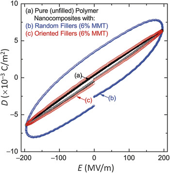
Tomer et al. Reference Tomer, Polizos, Randall and Manias53 found that highly oriented organically modified MMT (oMMT) has a measurable positive effect on the breakdown strength of polymer nanocomposites. Markedly lower dielectric losses were also observed in nanocomposites containing oriented oMMT as compared with its random counterparts, as shown in Figure 3 . However, at intermediate or high loadings of MMT, polymer-deficient structural defects, such as voids, form and usually result in a precipitous decline in dielectric breakdown strength of the polymer nanocomposite. Recently, in a model system composed of oMMT and poly(vinyl butyral), Fillery et al. Reference Fillery, Koerner, Drummy, Dunkerley, Durstock, Schmidt and Vaia54 showed that an idealized morphology of polymer nanocomposites to retard the breakdown cascade perpendicular to the electrodes will occur at intermediate volume fractions and resemble a discotic nematic phase where highly aligned, high-aspect-ratio nanometer-thick plates are uniformly surrounded by nanoscopic regions of polymer.
Displacement–electric field (D–E) loops showing the evolution of high field losses present in nanocomposites of polyethylene and montmorillonite (MMT); the effect of filler orientation is clearly illustrated by the marked widening of the loop. Adapted with permission from Reference 53.

On the other end of the composite spectrum, the role of the polymer matrix in energy storage performance should not be overlooked. For pure poly(vinylidene fluoride) (PVDF) films, Li et al. Reference Li, Meng, Zheng, Zhang, Xia and Xu55 demonstrated that thermal quenching of PVDF films (from 2000°C into ice water) induces a phase transformation from the polar α-phase to the nonpolar γ-phase, which could withstand a high electric field of ∼500 kV mm–1 and avoid early polarization saturation in the β-phase (an all-trans configuration of the polymer). Along similar lines, Tang and Sodano Reference Tang and Sodano56 followed a combined approach toward ultrahigh-energy-density polymer nanocomposites. Paraelectric Ba0.2Sr0.8TiO3 nanowires were coated with PVDF to form nanocomposite films. Thermal quenching of these nanocomposites from 2000°C into ice water not only induced γ-phase formation in PVDF, but also helped eliminate pores or voids formed during the casting process of the composite films. The resultant nanocomposites exhibited an ultrahigh energy density of 14.86 J cm–3 at 450 kV mm–1 and provided microsecond discharge times.
In addition to thermal treatments, the interplay between introduced nanoparticles and crystallization of the polymer matrix can also be exploited as an efficient means of modulating the crystalline phase of the polymer matrix. Tomer et al. Reference Tomer, Manias and Randall57 explored the synergy of hexafluoropropylene (HFP) comonomers and kaolinite clay nanofillers. This study showed that the addition of these high-aspect-ratio fillers to poly(vinylidene fluoride-co-hexafluoropropylene) (P[VDF-HFP]) copolymers did not increase the polar phase. With 5 wt% kaolinite clay nanofillers, the dielectric breakdown strength of the corresponding polymer nanocomposites was increased to ∼780 kV mm–1, giving rise to an electrical energy density of ∼19 J cm–3.
In addition to improving only the dielectric breakdown strength of polymer nanocomposites, novel approaches have also been proposed for the concurrent enhancement of the dielectric permittivity and, thereby of the electrical polarization. The most straightforward approach has been to employ dual nanofillers to improve both electrical polarization and breakdown strength. BaTiO3 spherical nanoparticles have been the most commonly used nanofillers for enhancing electrical polarization, whereas MMT nanoplatelets Reference Polizos, Tomer, Manias and Randall58 and hexagonal boron nitride nanosheets Reference Li, Han, Gadinski, Zhang and Wang59 have been used to improve dielectric breakdown strength.
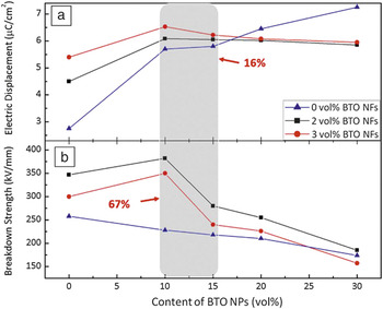
Recently, we proposed and demonstrated Reference Hu, Shen, Guan, Zhang and Lin60–Reference Zhang, Shen, Zhang, Gu, Hu, Du, Lin and Nan62 that very high energy densities can be achieved by simultaneously modulating the interfacial polarization and dielectric anisotropy of polymer nanocomposites. In the first demonstration system, Reference Hu, Shen, Guan, Zhang and Lin60,Reference Hu, Wang, Shen, Guan, Lin and Nan61 we prepared a class of topological-structure-modulated nanocomposites in which BaTiO3 nanoparticles were introduced in the outer composite layers to induce high electrical polarization, and BaTiO3 nanofibers were used in the central composite layer to improve the breakdown strength. The outer layers filled with BaTiO3 nanoparticles could be polarized up to a higher electric field, hence enhancing the electric displacement. As highlighted in the shaded region in Figure 4 , enhanced electric displacement and breakdown strength were achieved concomitantly. Through careful tuning of the relative thicknesses of the constituent layers, a maximum discharge energy density of 9.7 J cm–3 was achieved.
Variations of (a) maximum electric displacement and (b) breakdown strength of multilayer composites with the volume fractions of BaTiO3 nanoparticles (BTO NPs) in the outer layers and BaTiO3 nanofibers (BTO NFs) in the central layer. Also superimposed are data for composites filled solely with BTO NPs (denoted as 0 vol%). The concomitant enhancement of electric displacement (by 16%) and breakdown strength (by 67%) is highlighted in the shaded area. Adapted with permission from Reference 62.

In the second demonstration system, Reference Zhang, Shen, Zhang, Gu, Hu, Du, Lin and Nan62 we focused on the inside of ceramic nanofibers with the objective of introducing hierarchical interfaces in the corresponding polymer nanocomposites. TiO2 nanofibers embedded with BaTiO3 nanoparticles (BaTiO3@TiO2 nanofibers) were prepared by electrospinning and then fused with PVDF into polymer nanocomposite films. Inside the BaTiO3@TiO2 nanofibers, atomic-scale engineering of the hierarchical interfaces between BaTiO3@TiO2 generated a much increased dielectric permittivity, Reference Zhang, Chen, Wang, Shen, Gu, Lin and Nan63 whereas the high-aspect ratio and partial orientation of the BaTiO3@TiO2 nanofibers afforded the nanocomposites an improved breakdown strength, giving rise to an ultrahigh energy density of ∼20 J cm–3 with a dielectric breakdown strength of 646 kV mm–1.
Enhanced elastic properties of nanocomposites and their implications for the dielectric strength of capacitor films
As shown in Figure 1, the dielectric breakdown strengths of capacitor films have a direct influence on the electric energy densities of capacitors. For many polymer films, dielectric breakdown is controlled by electromechanical breakdown.
Reference O’Dwyer64–Reference Zhou, Zhao, Suo, Zou, Runt, Liu, Zhang and Zhang67
The Stark–Garton (S–G) model has been used widely to explain electromechanical breakdown in polymers.
Reference Stark and Garton68
Following this model, a polymer of initial thickness d
0 subjected to a voltage V deforms to thickness d, because of the induced electrostatic stress of
 $^1{/_2}{\varepsilon _r}{\varepsilon _0}{E^2}.$
For a linear elastic solid, the mechanical stress is Ye, where Y is the Young’s modulus and
 $e = \ln \left( {{d_0}/d} \right)$
is the true strain. At equilibrium, the electrostatic stress is balanced by the mechanical stress, σ. The electromechanical breakdown field occurs when the electrostatic stress cannot be balanced by the mechanical stress,
 ${E_B} = {\left( {Y/{\varepsilon _r}{\varepsilon _0}} \right)^{1/2}},$
and the polymer true strain at breakdown is
 ${e_B} = \ln \left( {{d_0}/{d_B}} \right){ = ^1}{/_2},$
where d
B is the polymer thickness at breakdown. However, for many polymers, the E
B value from the S–G model is far higher than the experimental data.
Reference Stark and Garton68–Reference Nash71
One reason for this inconsistency is that, for many polymers, such as the many semicrystalline polymers discussed in this article, the S–G model fails to capture the mechanical properties of the polymer. Many polymeric materials have yield strengths far below
 ${\sigma _B} = Y{e_B},$
as predicted by the S–G model. Using the yield strengths of polymers or a more general power-law relation to characterize the elastic–plastic deformation of semicrystalline polymers,
Reference Zhao, Hong and Suo72
one obtains the stress–strain relationship
 $$\sigma = K{e^N} = K{\left[ {\log \left( {{d_0}/d} \right)} \right]^N},$$
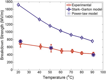
where K scales with the yield strength, and N is usually in the range of 0.1–0.6 for polymers developing plastic deformation. N = 1 corresponds to linear elasticity, where K = Y. As shown in Figure 5 , the power-law model of Zhou et al. matches extremely well with the breakdown strength of a P(VDF-HFP) copolymer. Reference Zhou, Zhao, Suo, Zou, Runt, Liu, Zhang and Zhang67
Experimentally determined breakdown field of poly(vinylidene fluoride-co-hexafluoropropylene) [P(VDF-HFP)] 95.5/4.5 mol% copolymer films as a function of temperature (circles). Predictions of the electromechanical breakdown strength of P(VDF-HFP) at various temperatures based on the Stark–Garton model and a power-law model are also presented. Reference Zhou, Zhao, Suo, Zou, Runt, Liu, Zhang and Zhang67

Compared with pure polymers, nanocomposites have the promise of improving the elastic modulus and yield strength of the dielectric films. Consequently, in addition to improving the dielectric constant, nanocomposites also have the potential to improve the elastic properties and dielectric strength of dielectric films, leading to improved energy density and capacitor performance. Reference Jordan, Jacob, Tannenbaum, Aharaf and Jasiuk73,Reference Shah, Maiti, Guun, Schmidt, Jiang, Batt and Giannelis74
Conclusions and future perspectives
Years of focused research have led to polymer nanocomposites with rather high energy densities of ∼20 J cm–3. It is now widely accepted that it takes multifaceted efforts to address various challenges in developing high-energy-density nanocomposites and reaching the full potential of these materials. The design of polymer nanocomposites requires the rational selection of nanoparticles and polymer matrices that takes into account their interplay and the consequent effects on the dispersion of nanoparticles and on the nano- and mesoscale morphologies of the polymer matrix, interface engineering that not only promotes the homogeneous dispersion of nanoparticles, but also modulates the critical interfacial polarization. As dielectric media subjected to rather high electrical fields, polymer nanocomposites are also extremely sensitive to any structural defects that can have detrimental effects on their dielectric breakdown strength and compromise their energy storage performance, or even counteract any benefits obtained through rational design of the nanocomposite microstructure. Careful control of processing conditions is thus equally, if not more, important for the rational design of polymer nanocomposites.
Acknowledgments
Financial support from the National Basic Research Program of China (Grant No. 2015CB654603), the NSF of China (Grant No. 51222204), and ONR under Grant No. N00014-14-1-0109 are appreciated.