1. Introduction
Nonlinear systems, such as parallel robots, use techniques that require full dynamic models for control. One of the techniques used to solve these systems is the sliding mode controller with adaptive backstepping, which is an alternative to feedback linearization that provides stability and tracking to the system [Reference Mazare and Taghizadeh1, Reference Alyoussef and Kaya2]. The adaptive controller allows the user to estimate the unknown dynamic system parameters, while the sliding modes controller solves the unmodeled dynamics and external disturbances [Reference Zeinali and Notash3]. The sliding mode control produces a switching control law to force the system to converge to the sliding surface within a boundary layer near the sliding surface under the convergence of the Lyapunov stability theory. This approach solves unmodeled dynamics and external disturbances [Reference Dachang, Baolin, Puchen and Wu4], while the adaptive controller allows the user to estimate the unknown dynamic system parameters. Moreover, the backstepping control is used to deal with nonlinear systems in which the states are used as virtual control signals in control law design, and the virtual signals and their derivatives are required at every step of the design process [Reference Dachang, Baolin, Puchen and Wu4, Reference Yu, Shi and Zhao5]. The main advantage of the backstepping scheme is its ability to handle systems with different relative degrees (the difference between the number of poles and zeros).
Coutinho et al. [Reference Coutinho and Hess-Coelho6] used two controls, the first of which was a hybrid control derived from the combination of a pure PD (Proportional derivative) control with a modified sliding mode control. The second combined a pure computed torque with the altered sliding mode control. The simulations and the experimental results show a significant reduction in the path tracking and steady-state errors in both hybrid control strategies. Mazare et al. [Reference Mazare and Taghizadeh1] proposed a controller that combined an adaptive sliding mode and backstepping methods to perform exact tracking control of a parallel robot. This is because it uses an adaptive approach to estimate the uncertainties and disturbances of the dynamic model and a Lyapunov function to prove the controller’s stability. The dynamic robot model was obtained using the Lagrangian method, which is robust with time-varying disturbances. Furthermore, the controller’s performance is evaluated using simulated trajectories with some precision point optimization using harmony search algorithm (HSA) and interpolation spline cubic (ISC). In a study by Wang et al. [Reference Wang, Lin, Zhou, Shi and Wang7], the backstepping sliding mode robust control was proposed for a wire-driven parallel robot (WDPR) system used in a wind tunnel test to dominate the motion of the end effector. The backstepping design method was adopted and a sliding mode term was introduced to construct a controller, while the disturbances were compensated in the controller to reduce the switching gain, thereby guaranteeing robustness. For the sake of verifying the stabilization of the closed-loop system, the Lyapunov function was constructed to analyze the system’s stabilization.
Since rehabilitation robots directly operate with the user (physiotherapist/patient), physical interaction must be controlled to ensure the user’s safety. Moreover, the level of forces applied and limb or joint movements must be regulated so that the rehabilitation goal is achieved. An example of this is provided by the research of Azcaray et al. [Reference Azcaray, Blanco, García, Adam, Reyes, Guerrero and Guzmán8] and Guzmán et al. [Reference Guzmán-Valdivia, Carrera-Escobedo, Blanco-Ortega, Oliver-Salazar and Gómez-Becerra9] which used PID (Proportional integral derivative) control techniques in ankle rehabilitators. Other authors state that there are also combinations of this technique, such as the FOPID (fractional-order proportional integral derivative) by Sinasi Ayas et al. [Reference Sinasi-Ayas, Hakki-Altas and Sahin10], impedance control by Magadán et al. [Reference Magadán, Blanco, Gama and Abúndez11] as well as sliding modes by Chen et al. [Reference Chen, Zhou, Vanderborght, Wang and Wang12]. In another work, Li et al. [Reference Li, Zuo, Zhang, Dong, Zhang, Tao and Ji13] described an ankle robot based on a parallel mechanism actuated using four pneumatic muscle actuators to provide three rotational degrees of freedom to the ankle joint. The controller adaptive impedance control was used with the patients’ active participation to provide customized robotic assistance. In addition, Wang et al. [Reference Wang, Chang and Zhu14] presented an internal model control (IMC) controller. The simulation showed that the composite two-degrees of freedom (2-DOF) IMC controller provided a high level of performance, with the experimental results showing the effectiveness of passive training of the given trajectory and impedance training active control strategy. Dong et al. [Reference Dong, Wenpei, Jianfeng, Xiaodong, Xi, Yuan and Yu15] developed an ankle robotic system with three rehabilitation training strategies based on admittance control and its derivatives. The controller’s output is obtained based on proportional and time-shifting methods according to the continuous measured torque which considers the patient’s muscle strength level and different stages of recovery. In a further study, Zhang M. et al. [Reference Zhang, Mcdaid, Veale, Peng and Xie16] proposed an adaptive patient-cooperative control strategy to improve rehabilitator-assisted ankle efficacy and safety by developing and implementing a compatible ankle rehabilitation robot.
Recently, the adaptive backstepping sliding mode control has been applied to ankle rehabilitation robots in some studies. For example, Qingsong et al. [Reference Qingsong, Chengxiang, Jie, Meng, Liu, Xie and Yang17] explained that human–robot external disturbance can be estimated by an observer which is used to adjust the robot output to accommodate external changes. This means, therefore, that the system’s stability is guaranteed by the Lyapunov theorem. In the study by Salimi et al. [Reference Salimi-Lafmejani, Tale-Masouleh and Kalhor18], the position control of the pneumatic actuator was performed based on the backstepping sliding mode controller according to the system’s dynamic model. The results show the efficiency of the control strategy and the proposed method for calculating the position of the end effector. In another study, Mohanta et al. [Reference Mohanta, Mohan, Takeda, Corves and Uhl19] presented an adaptive backstepping motion control of a sitting-type lower limb rehabilitation robot. The proposed robot kinematics and dynamics were discussed, and its motion control design in the workspace was based on an adaptive backstepping control strategy which is derived herein. With Lyapunov’s direct method, the closed-loop system stability of the proposed motion control scheme can be demonstrated. For numerical simulations, in order to validate the motion control strategy effectiveness and the proposed lower limb rehabilitation robot design, the clinically obtained test gait data is used for the desired motion trajectory.
In this work, a robust control scheme for a rehabilitation parallel robot is proposed and implemented numerically and experimentally to prove its effectiveness. The desired trajectory is generated for each of its actuators, meaning that a decentralized active disturbance rejection controller (ADRC) is used for each prismatic actuator. The purpose of the ADRC is that uncertainties, external disturbances, and modeling errors are all integrated as an extended state which is estimated and compensated by the extended state observer (ESO) [Reference Shi, Wu, He, Li, Ding and Liu20]. The parallel robot has two active prismatic joints, each with two linear bearings guided by two axes and driven by a power screw, which is coupled to a permanent magnet DC electric motor. The controller design is based on the backstepping technique and ESOr [Reference Linares, Hernández, Guerrero, Mino, Espinosa and Zurita21]. The observer and the controller synchronize and regulate the position of the prismatic actuator, ensuring the robustness of trajectory tracking in each actuator. Finally, the proposed controller facilitates its numerical and experimental application in real time.
2. Parallel robot description
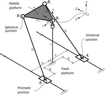
The parallel robot consists of a mobile platform and a fixed base connected by two PUS (prismatic, universal, and spherical joints) kinematic chains as well as an RR (revolute-revolute) chain (Fig. 1).There are 2-DOF to generate the inversion/eversion and flexion/extension movements, along with the adduction/abduction movements. For the first movement, the rotation of the mobile platform that generates flexion/extension and abduction/adduction movement is blocked, while to generate flexion/extension and abduction/adduction movements, the inversion/eversion DOF is blocked. The arrangement of the kinematic chains allows the prismatic joints axes to be parallel to the
 $Z$
axis global coordinate system. The universal joints’ centers are designated as
 $A_1$
and
 $A_2$
, while the spherical joints’ locations and the mobile platform are denoted by
 $B_1$
,
 $B_2$
, and
 $B_3$
. The mobile platform coordinates are coplanar to simplify the analyses. The global coordinate system is
 $O_{XYZ}$
and the moving reference is
 $P_{xyz}$
, where point
 $O$
and
 $P$
are the intersection points of the central pole revolute joints. The longitudinal axis of the
 $Y$
axis is colinear to the central pole longitudinal axis [Reference Flores-Salazar, Arias-Montiel, Lugo-González, Gallardo-Alvarado, Tapia Herrera and Uhl22, Reference Flores-Salazar, Garcí-Murillo, Lugo-González, Gallardo-Alvarado, Arias-Montiel, Barrangan-Mendoza, Palafox-Delgado and Santiago Santos23].
Parallel robot 2PUS+RR [Reference Flores-Salazar, Arias-Montiel, Lugo-González, Gallardo-Alvarado, Tapia Herrera and Uhl22].

With regard to the analysis of the parallel robot direct kinematics, in Flores et al. [Reference Flores-Salazar, Arias-Montiel, Lugo-González, Gallardo-Alvarado, Tapia Herrera and Uhl22], the Sylvester dialytic elimination method was presented, as it consisted of reducing any system of polynomial equations into a single polynomial with one unknown. This approach was used to obtain all the possible locations of the mobile platform, in addition to the exact solutions of the system of equations. In Flores et al. [Reference Flores-Salazar, Garcí-Murillo, Lugo-González, Gallardo-Alvarado, Arias-Montiel, Barrangan-Mendoza, Palafox-Delgado and Santiago Santos23], the velocity and acceleration analysis was also performed using the screw theory. By systematically applying Klein’s form, the passive velocities and accelerations are canceled, and two systems of linear equations are obtained that link the mobile platform’s velocities and accelerations with the actuators’ velocities and accelerations, respectively. Singularity calculations (configurations where the mobile platform gains or loses degrees of freedom) are also obtained using screw theory based on velocity analysis equations that link the mobile platform’s angular velocities to the actuators’ linear velocities.
2.1. Inverse kinematics
The inverse kinematics analysis consists of finding the displacement variables
 $q_i$
, given the mobile platform coordinates
 $\boldsymbol{P}_{x,y,z}$
. Any rigid body position can be specified by knowing their three coordinate points [Reference Garcia-Murillo, Takeda, Castillo-Castaneda, Matsuura, Kawasumi and Gallardo-Alvarado24]. The mobile platform position, compared to the fixed reference frame
 $O_{XYZ}$
, can be determined by calculating the coordinates of points
 $B_i$
[Reference Flores-Salazar, Garcí-Murillo, Lugo-González, Gallardo-Alvarado, Arias-Montiel, Barrangan-Mendoza, Palafox-Delgado and Santiago Santos23]. Then, the equations that include these variables are written using mechanical constraint expressions, where the robot limbs lengths
 $d_i$
are constrained to
 \begin{align} \left ({{{\boldsymbol{B}}_i} -{\boldsymbol{A}_i}} \right ) \cdot \left ({{\boldsymbol{B}_i} -{\boldsymbol{A}_i}} \right ) = d_i^2 \,\,\,\,\,\,\,\,\,\,\,\, \forall i = 1,2 \end{align}
Developing the equations given in Eq. (1) and obtaining
 $q_1$
and
 $q_2$
:
 \begin{align}{q_1} ={Z_1} \pm \sqrt{X_1^2 - 2bX_1 - Y_1^2 - 2c{Y_1} -{b^2} -{c^2} +{d_1^2}} \end{align}
 \begin{align}{q_2} ={Z_2} \pm \sqrt{X_2^2 + 2bX_2 - Y_2^2 - 2c{Y_2} -{b^2} -{c^2} +{d_2^2}} \end{align}
 \begin{align} \left [{\begin{array}{*{20}{c}}{{X_i}}\\{{Y_i}}\\{{Z_i}} \end{array}} \right ] =\boldsymbol{R}{ B_i} \end{align}
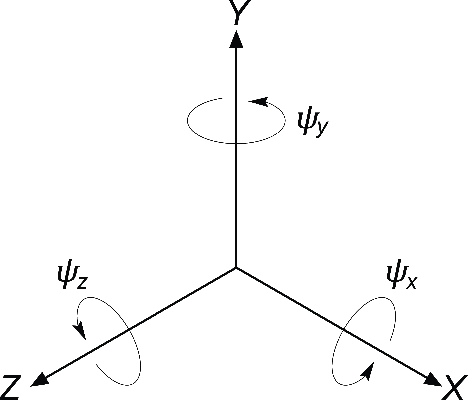
Rotation angles on the global coordinate system.

 $\boldsymbol{R}$
is the rotation matrix on the global coordinate system (Fig. 2) formed by the rotation matrices
 $\boldsymbol{R}_x$
,
 $\boldsymbol{R}_y$
, and
 $\boldsymbol{R}_z$
:
 \begin{align} \boldsymbol{R} &= \boldsymbol{R}_y\,\boldsymbol{R}_z\, \boldsymbol{R}_x \end{align}
 \begin{align}{\boldsymbol{R}_x} &= \left [{\begin{array}{*{20}{@{\quad}c}} 1&0&0\\ 0&{\cos\! \left ({{\psi _x^*}} \right )}&{ - \sin\! \left ({{\psi _x^*}} \right )}\\[3pt] 0&{\sin\! \left ({{\psi _x^*}} \right )}&{\cos\! \left ({{\psi _x^*}} \right )} \end{array}} \right ]\nonumber \\[1em]{\boldsymbol{R}_y} &= \left [{\begin{array}{*{20}{@{\quad}c}}{\cos\! \left ({{\psi _y^*}} \right )}&0&{\sin\! \left ({{\psi _y^*}} \right )}\\ 0&1&0\\{ - \sin\! \left ({{\psi _y^*}} \right )}&0&{\cos\! \left ({{\psi _y^*}} \right )} \end{array}} \right ]\\[1em]{\boldsymbol{R}_z} &= \left [{\begin{array}{*{20}{@{\quad}c}}{\cos\! \left ({{\psi _z^*}} \right )}&{ - \sin\! \left ({{\psi _z^*}} \right )}&0\\[3pt]{\sin\! \left ({{\psi _z^*}} \right )}&{\cos\! \left ({{\psi _z^*}} \right )}&0\\[3pt] 0&0&1 \end{array}} \right ]\nonumber \end{align}
By knowing the mobile platform’s velocity, the actuator’s velocity is calculated by
 $\boldsymbol{\dot{\boldsymbol{Q}}}$
:
 \begin{align} \boldsymbol{\dot{\boldsymbol{Q}}}=\boldsymbol{\boldsymbol{B}^{-1}}AVo \end{align}
By knowing the mobile platform’s acceleration, the actuators’ acceleration is calculated by
 $ \boldsymbol{\ddot{\boldsymbol{Q}}}$
:
 \begin{align} \boldsymbol{\ddot{\boldsymbol{Q}}}= \boldsymbol{\boldsymbol{B}^{-1}} {( \boldsymbol{A}\boldsymbol{A}\boldsymbol{o} - \boldsymbol{C}_\boldsymbol{a})} \end{align}
By having the desired accelerations, velocities, and displacements to be applied to the system, the magnitudes and directions of the necessary forces and torques to generate the desired motions can be obtained.
2.2. Dynamic model
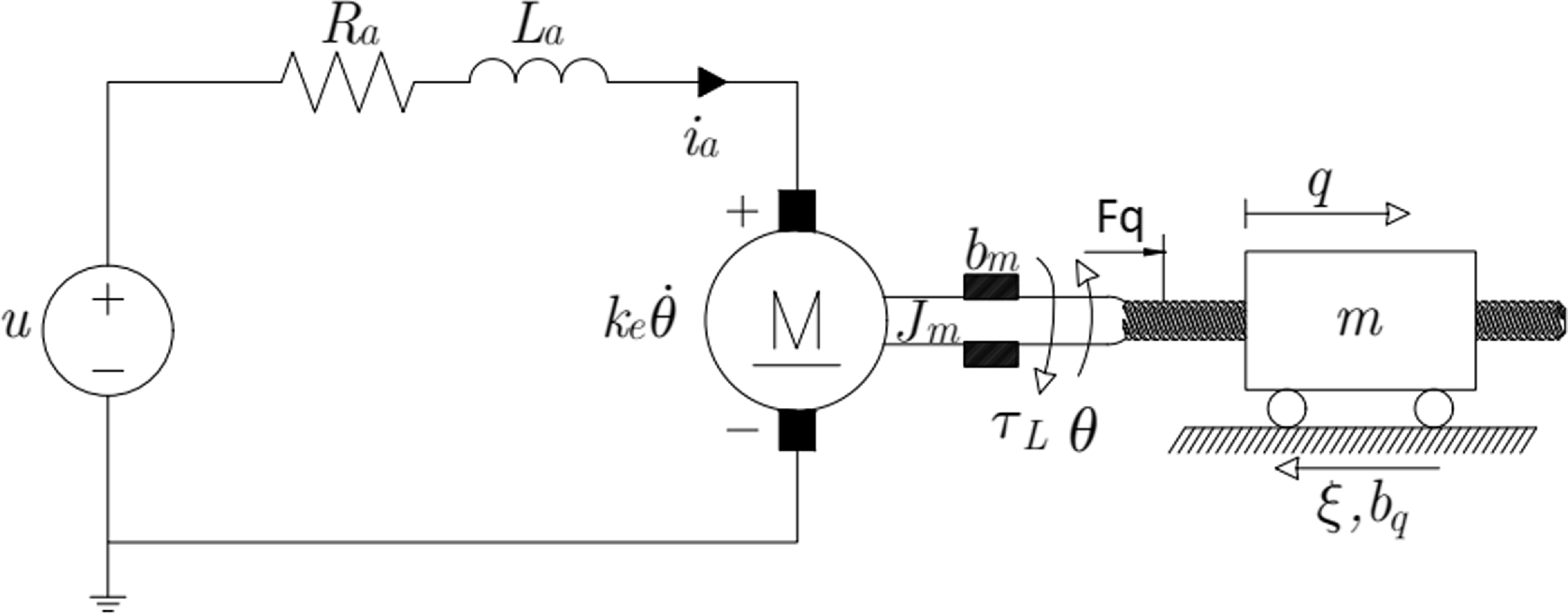
The parallel robot dynamics modeling is based on the dynamics of two slides, each one with two linear bearings guided by two axes and driven by a power screw which is coupled to an electric motor (Fig. 3). Viscous damping,
 $b_q$
, is considered on both linear slides between them and the corresponding guides, as well as between the nut and the screw. For the displacement in
 $q$
, there is an input force denoted by
 $F_q$
. The forces generated in each movement due to the mobile platform weight and the foot weight force are considered as perturbations
 $\xi$
.
Electric linear actuator.

The DC motor dynamic model shown in Fig. 3, using Kirchhoff’s law and Newton’s second law, can be written as follows:
 \begin{align}{L_a}\frac{{d{i_a}}}{{dt}} = -{R_a}{i_a} -{k_e}\dot \theta + u \end{align}
 \begin{align}{J_m}\ddot \theta ={k_m}{i_a} -{b_m}\dot \theta -{\tau _L} \end{align}
In permanent magnet DC motors, there is a very small armature inductance, therefore,
 $L_a \approx 0$
considering
 ${L_a}\dfrac{{d{i_a}}}{{dt}} \approx 0$
, meaning that the dynamic variable
 $i_a$
can be static:
 \begin{align}{{\bar i}_a} = \left ({\frac{{u -{k_e}\dot \theta }}{{{R_a}}}} \right ) \end{align}
By substituting Eq. (11) in Eq. (10), the following expression is obtained:
 \begin{align}{J_m}\ddot \theta = - \left ({\frac{{{k_m}{k_e}}}{{{R_a}}} +{b_m}} \right )\dot \theta + \left ({\frac{{{k_m}}}{{{R_a}}}} \right )u -{\tau _L} \end{align}
The dynamic model for the mobile mass shown (see in Fig. 3), using Newton’s second law, can be written as:
 \begin{align} m\ddot q +{b_q}\dot q + \xi ={F_q} \end{align}
To couple the DC motor and the mobile mass dynamics, the following is considered:
 \begin{align} \theta = \frac{q}{p},\,\,\, \dot \theta = \frac{{\dot q}}{p},\,\,\, \ddot \theta = \frac{{\ddot q}}{p},\,\,\,{\tau _L} = p{F_q} \end{align}
 \begin{align} \underbrace{\left ({\frac{{{J_m}}}{p} + mp} \right )}_{{:= J_\textit{eq}}}\ddot q = - \underbrace{\left ({\frac{{{k_m}{k_e}}}{{{R_a}p}} + \frac{b_m}{p}}+{b_q}p \right ) }_{:=\alpha } \dot q + \underbrace {\left ({\frac{{{k_m}}}{{{R_a}}}} \right )}_{:=\beta } u-p\xi \end{align}
Representing the system in state variables,
 $x_1 = q$
and
 $x_2 = \dot{q}$
:
 \begin{align} \begin{array}{*{20}{l}}{{{\dot x}_1} ={x_2}}\\{{{\dot x}_2} ={\Phi\! \left ({{x_2},\xi } \right )} + \left ({\dfrac{\beta }{{{J_\textit{eq}}}}} \right )u} \end{array} \end{align}
 \begin{align} \Phi\! \left ({{x_2},\xi } \right ) = - \left ({\frac{\alpha }{{{J_\textit{eq}}}}} \right )\dot q - \left ({\frac{p}{{{J_\textit{eq}}}}} \right )\xi \end{align}
The function
 $\Phi$
is assumed to be unknown but is bounded. The dynamics of both actuators can be considered as decoupled, meaning that control strategies for tracking separate position planned trajectories are proposed.
3. Backstepping control
The backstepping design showed more flexibility compared to the feedback linearization, since it does not require the resulting input–output dynamics to be linear. The cancelation of potentially useful nonlinearities can be avoided resulting in less complex controllers [Reference Khalil25]. The backstepping technique uses a Lyapunov function for solving the stability of each of the blocks, until reaching the controller design. It starts from the Eq. (16) dynamic model, choosing the output displacement as
 $q = x_1$
. The second step is to formulate a candidate Lyapunov function. The next step is to formulate the backstepping control law, and an analysis of the system’s stability is then performed. Finally, the feedback control system is simulated to verify that the plant’s controlled outputs meet the previously established design specifications and that the designed control system a shows stable behavior.
For the origin to be stable, by using Lyapunov’s theorem, the first candidate function must be positive definite and its semidefinite derivative negative, thus the following function is proposed:
 \begin{align} V\! \left ({{z_1}} \right ) = \frac{1}{2}z_1^2 \end{align}
where
 $z_1$
denotes the selected output tracking error:
 \begin{align}{z_1} ={x_1} - x_1^* \end{align}
where
 $x_1^*$
is the desired actuator position.
The Lyapunov candidate function is positive definite by
 $V\!\left ({{z_1}} \right ) > 0 -\left \{{0} \right \}$
, where its time derivative is
 \begin{align} \dot V\!\left ({{z_1}} \right ) ={z_1}{{\dot z}_1} \end{align}
where
 ${\dot z}_1$
is the tracking error derivative:
 \begin{align}{{\dot z}_1} ={{\dot x}_1} - \dot x_1^* ={x_2} - \dot x_1^* \end{align}
where
 $x_2$
is an output displacement.
Substituting
 ${\dot x}_1$
from Eq. (16) in Eq. (21) as an intermediate step, the tracking error
 $z_2$
is proposed, which involves the virtual controller
 $\gamma\! \left ( x \right )$
to make
 $\dot V\!\left ({{z_1}} \right )$
semidefinite negative:
 \begin{align} \dot V\!\left ({{z_1}} \right ) ={z_1}\!\left ({{x_2} - \dot x_1^*} \right ) \end{align}
 \begin{align}{z_2} ={x_2} - \gamma\! \left ( x \right ) \end{align}
Obtaining
 $x_2$
from Eq. (23), results in:
 \begin{align}{x_2} ={z_2} + \gamma\! \left ( x \right ) \end{align}
and by substituting Eq. (24) for Eq. (22), the following expression is obtained:
 \begin{align} \dot V\!\left ({{z_1}} \right ) ={z_1}\!\left ({{z_2} + \gamma \left ( x \right ) - \dot x_1^*} \right ) \end{align}
Now, a virtual controller is proposed
 $\gamma\! \left ( x \right )$
, to cancel the term
 $\dot x_1^*$
and make
 $\dot V\!\left ({{z_1}} \right )$
negative semidefinite:
 \begin{align} \gamma\! \left ( x \right ) = -{k_1}{z_1} + \dot x_1^* \end{align}
where
 $k_1>0$
is a constant value that defines the sensitivity of tracking error proportional of variable
 $z_1$
. By substituting Eq. (26) for Eq. (25), the following expression is obtained:
 \begin{align} \dot V\!\left ({{z_1}} \right ) = -{k_1}{z_1^2} +{z_1}{z_2} \end{align}
Proposing a Lyapunov control function as follows:
 \begin{align} V\!\left ({{z_1},{z_2}} \right ) = V\!\left ({{z_1}} \right ) + \frac{1}{2}z_2^2 \end{align}
Deriving the Lyapunov function compared to time, the following is obtained:
 \begin{align} \dot V\!\left ({{z_1},{z_2}} \right ) = \dot V\left ({{z_1}} \right ) +{z_2}{{\dot z}_2} = -{k_1}{z_1^2} +{z_2}\!\left ({{z_1} +{{\dot z}_2}} \right ) \end{align}
where
 ${\dot z}_2$
is obtained by deriving the Eq. (23) as:
 \begin{align}{{\dot z}_2} ={{\dot x}_2} - \dot \gamma \left ( x \right ) \end{align}
 \begin{align}={{\dot x}_2} +{k_1}{{\dot z}_1} - \ddot x_1^* \end{align}
 \begin{align} = \Phi\! \left ({{x_2},\xi } \right ) + \dfrac{\beta }{{{J_\textit{eq}}}}u +{k_1}{{\dot z}_1} - \ddot x_1^* \end{align}
Finally, a control law is proposed that makes the function
 $\dot V\left ({{z_1},{z_2}} \right )$
semidefinite negative:
 \begin{align} u = - \frac{{{J_\textit{eq}}}}{\beta }\left [{{k_2}{z_2} +{z_1} + \hat{\Phi }\! \left ({{x_2},\xi } \right ) +{k_1}{{\dot z}_1} - \ddot x_1^*} \right ] \end{align}
where
 $\hat{\Phi }\! \left ({{x_2},\xi } \right )$
is a function to be estimated through an ESO, and
 $k_2>0$
is a constant value defining the sensitivity tracking error proportional of variable
 $z_2$
. Substituting the Eq. (33) for Eq. (29), the following expression is obtained:
 \begin{align} \dot V\!\left ({{z_1},{z_2}} \right ) = -{k_1}{z_1^2} -{k_2}{z_2^2} +{z_2} \tilde{\Phi } \left ({{x_2},\xi } \right ) \end{align}
with
 \begin{align} \tilde{\Phi }\! \left ({{x_2},\xi } \right ) ={\Phi }\! \left ({{x_2},\xi } \right ) - \hat{\Phi }\! \left ({{x_2},\xi } \right ) \end{align}
For the function defined in Eq. (34) to be negative semidefinite and ensure asymptotic stability, the function
 $\hat{\Phi }$
must be bounded as follows:
 \begin{align} \tilde{\Phi }\! \left ({z_2}\right ) \le k_2 \|{{z_2}} \| \end{align}
4. Extended state observer
An ESO is designed for an online estimation of the
 $\Phi$
function and the states
 $x_1$
and
 $x_2$
where the estimated values are adapted to the backstepping controller references. The following assumptions are made for the ESO design.
-
• The only variable available for measurement is
 $x_1$
.
-
• The
$R_a$
,
$J_m$
,
$k_m$
,
$m$
, and
$p$
parameters are known. -
• The estimated value of the
$\Phi$
function, which includes structured and unstructured uncertainties, is considered an unknown but bounded function. -
• The estimate of the unknown function
$\Phi$
is denoted by
$\eta _1$
. -
• The estimates of the output
$x_1$
are successive derivatives and are denoted by
$y_1 = \hat{x}_1$
and
$y_2 = \hat{x}_2$
.


Taking the mobile mass dynamic model from Eq. (37), the ESO is designed as:
 \begin{align} \begin{array}{l}{{\dot y}_1} ={y_2} +{\lambda _3}\!\left ({x_1 -{y_1}} \right )\\[2pt]{{\dot y}_2} ={\eta _1} + \left ({\dfrac{\beta }{{{J_\textit{eq}}}}} \right )u +{\lambda _2}\!\left ({x_1 -{y_1}} \right )\\[2pt]{{\dot \eta }_1} ={\eta _2} +{\lambda _1}\!\left ({x_1 -{y_1}} \right )\\[2pt]{{\dot \eta }_2} ={\lambda _0}\!\left ({x_1 -{y_1}} \right ) \end{array} \end{align}
The selection of constant coefficients
 $\{{\lambda _3},{\lambda _2},{\lambda _1},{\lambda _0}\}$
, such as the Hurwitz polynomial coefficients, is such that the roots of the characteristic polynomial dominate the output estimation error dynamics’ behavior, placing them in the left half-plane of the complex plane. Therefore, a fourth-order polynomial was selected given by:
 \begin{align} P\!\left ( s \right ) ={\left ({{s^2} + 2\zeta{\omega _n}s + \omega _n^2} \right )^2} \end{align}
From this, the coefficient final values are given by:
 \begin{align} \begin{array}{l}{\lambda _0} = \omega _n^4\\[2pt]{\lambda _1} = 4\zeta \omega _n^3\\[2pt]{\lambda _2} = 4{\zeta ^2}\omega _n^2 + 2\omega _n^2\\[2pt]{\lambda _3} = 4\zeta{\omega _n} \end{array} \end{align}
for
 $0 < \zeta < 1$
and
 ${\omega _n} > 0$
.
5. Desired trajectories
The desired trajectories for the actuators displacement
 ${q^*}$
,
 ${{\dot q}^*}$
and their corresponding velocity
 ${\dot q}^*$
and acceleration
 ${\ddot q}^*$
are obtained by the inverse kinematic analysis of the parallel robot. The desired trajectories
 $\psi _n^*$
and their corresponding velocity
 $\dot{\psi } _n^*$
and acceleration
 $\ddot{\psi } _n^*$
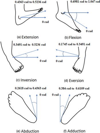
are proposed as Bézier polynomials as in Eq. (40). These trajectories represent the ankle movements as shown in Fig. 4, and the rehabilitation movements start from an initial position and reach a final position with a smooth change [Reference Blanco, Gomez, Vela and Delgado26].
Ankle movements [Reference Lippert27].

 $\forall n = x,y,z$
, where:
 \begin{align} \psi _n^* = \left \{{\begin{array}{*{20}{l}}{{{\bar \psi }_{{n_{0}}}}}\\{{{\bar \psi }_{{n_{0}}}} + \left ({{{\bar \psi }_{{n_{f}}}} -{{\bar \psi }_{{n_{0}}}}} \right ){\phi }\left ({t,{t_{0}},{t_{f}}} \right )}\\{{{\bar \psi }_{{n_{f}}}}} \end{array}} \right .\begin{array}{*{20}{l}}{{\rm{for}}\,\, t \lt {t_{0}}}\\{{\rm{for}}\,\,{t_{0}} \le t \le{t_{f}}}\\{{\rm{for}}\,\, t \gt {t_{f}}} \end{array} \end{align}
 \begin{align} \phi\! \left ({t,{t_{0}},t_{f}} \right ) = \left ({\frac{{t -{t_{0}}}}{{{t_{f}} -{t_{0}}}}} \right )^5 \sum _{i=0}^{5}\left (-1\right )^i \sigma _i\left ({\frac{{t -{t_{0}}}}{{{t_{f}} -{t_{0}}}}} \right )^i \ \end{align}
with parameters of the polynomial function:
 $\sigma _0 = 252, \,\, \sigma _1 = 1050, \,\, \sigma _2 = 1800, \,\, \sigma _3 = 1575, \,\, \sigma _4 = 700, \,\, \sigma _5 = 126.$
6. Result and discussion
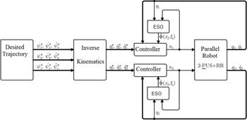
In order to validate the proposed controller-observer scheme, a MATLAB-ADAMS cosimulation was carried out and a block diagram of the closed-loop system is depicted in Fig. 5. ADAMS is a computational software focused on the dynamic analysis of multibody systems, and its main objective is to solve nonlinear problems. It facilitates the analysis of the dynamics of moving parts, as well as the loads and forces that are distributed along the mechanical systems [Reference McConville28]. Moreover, a MATLAB-Simulink is a block diagram environment for multidomain simulations and model-based designs. The simulation software calculates model behavior as conditions evolve over time or as events occur and can be used to evaluate a new design, diagnose problems with an existing design, and test a system under conditions that are difficult to reproduce [Reference Moore29].
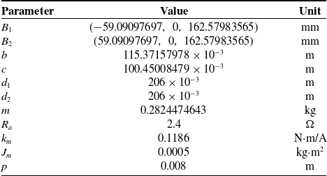
Robot’s parameters.

Control diagram.

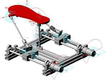
Virtual prototype on MSC ADAMS.

The virtual prototype in a MSC ADAMS environment is shown in Fig. 6, and the numerical parameters used in the cosimulation are presented in Table I.
For simulation purposes, an external disturbance
 $\xi _P$
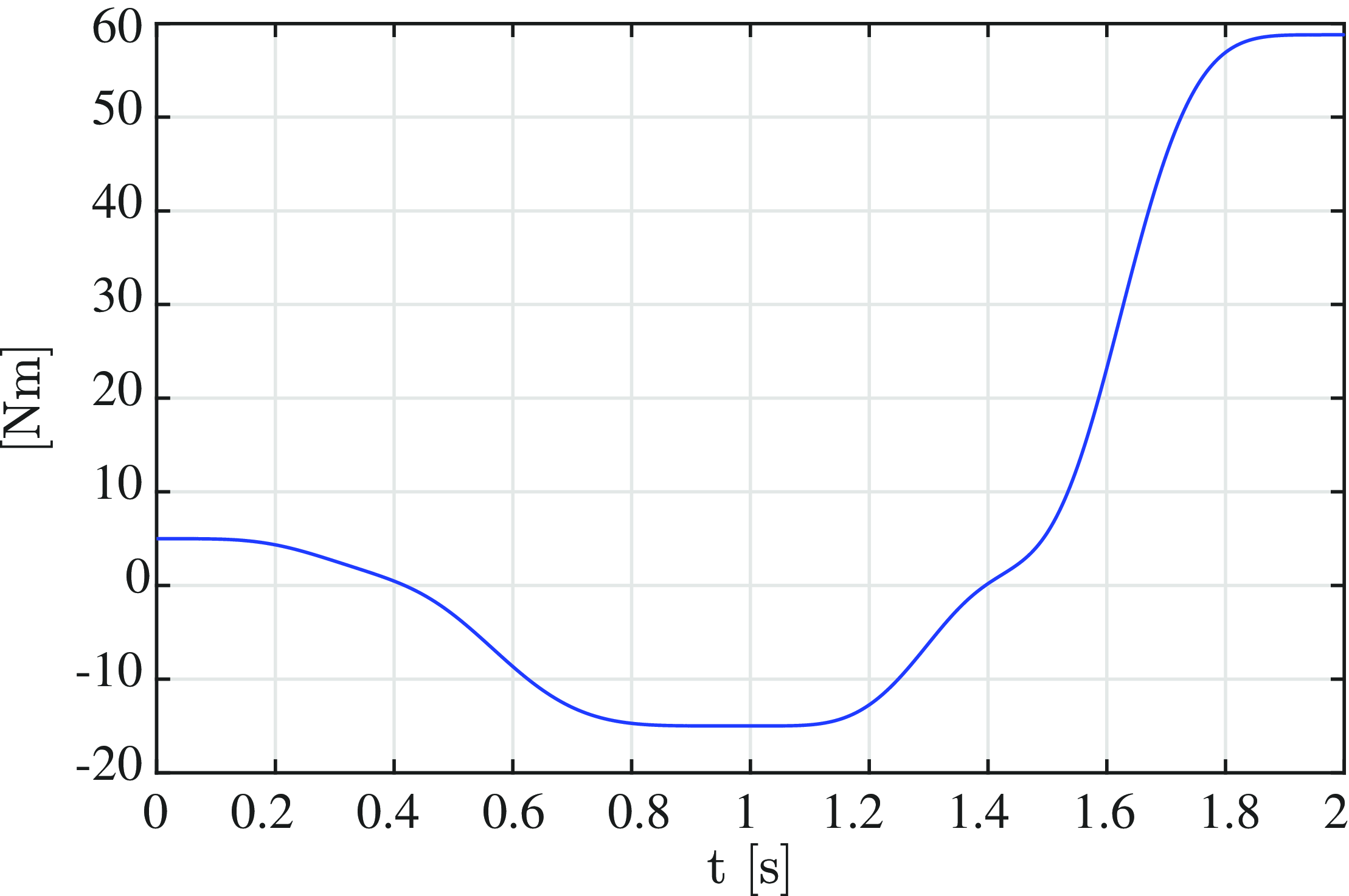
is added. This disturbance emulates the torque required to carry out the flexion/extension passive motion in an ankle rehabilitation therapy [Reference Andrade, Lacourpaille, Freitas, Mcnair and Nordez30] and is shown in Fig. 7. This torque is applied to the mobile platform on the global
 $X$
-axis direction, and can be approximated by a fourth-order polynomial given by (42):
External disturbance
 $\xi _P$
.

 \begin{align} \xi _P = 4.2614e^{-6}\psi _x^4 - 6.4331e{-4}\psi _x^3 + 0.0212\psi _x^2 - 0.4632\psi _x + 4.9973 \end{align}
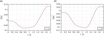
The actuators position tracking response: (a) position of actuator 1 and (b) position of actuator 2.

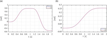
The mobile angular position tracking response: (a) flexion/extension motion and (b) abduction/adduction motion.

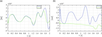
Dynamics of error tracking: (a) tracking error dynamic for two actuators and (b) tracking error dynamic for mobile platform.

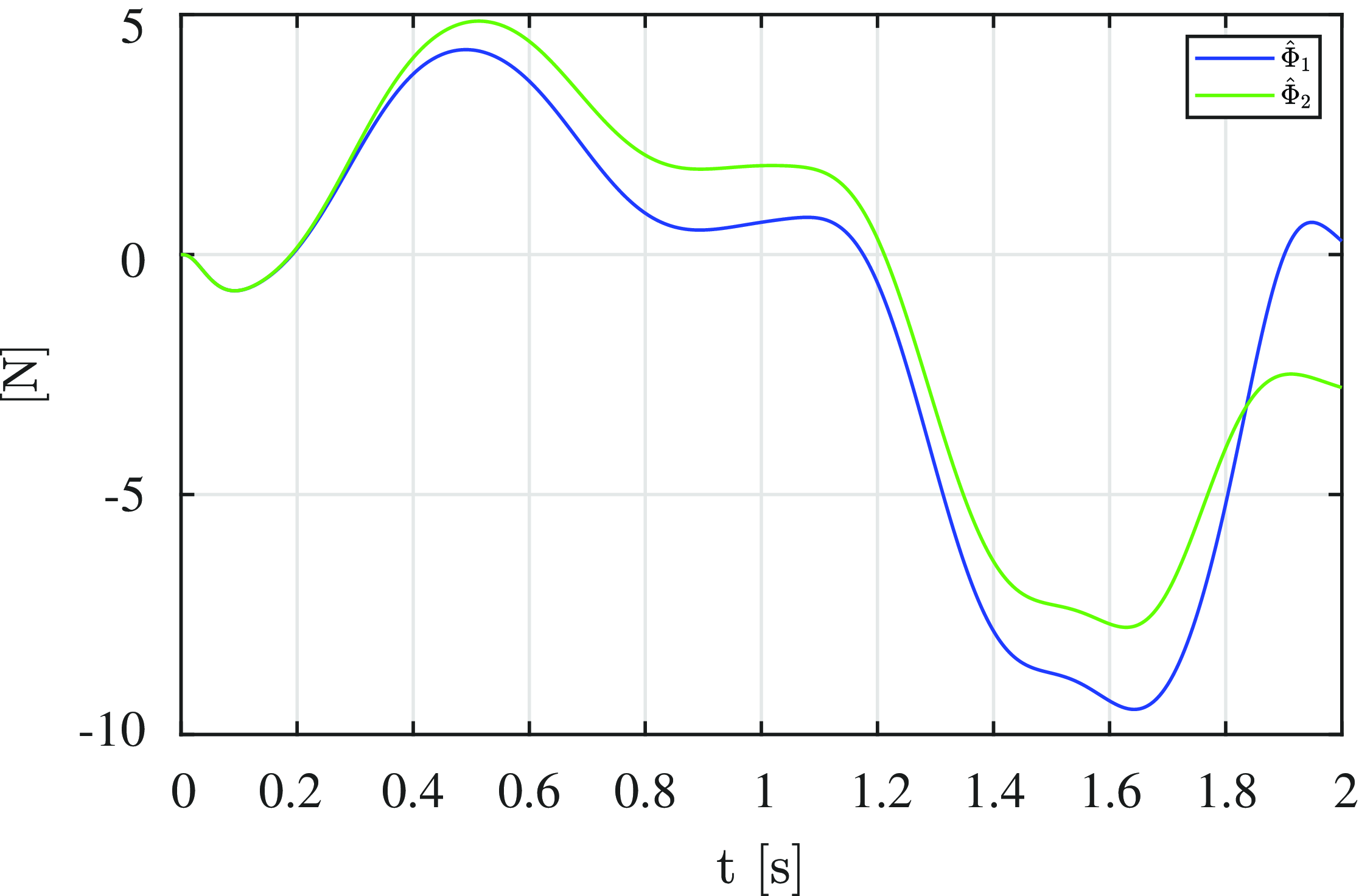
Estimated value of functions
 $\Phi$
, during the coupling of the dynamics of the DC motor and the link considering the uncertainties of both, as well as the disturbances caused by the movement and force of the foot on each actuator.

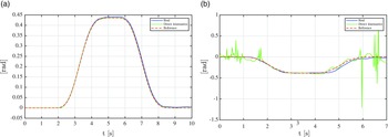
Figure 8 shows the trajectories generated by the inverse kinematic analysis and the actuators’ position with the proposed controller for trajectory tracking. The mobile platform’s motion and the desired trajectories use the Bézier-type polynomial [see Eq. (40)] to generate a combined flexion/extension and abduction/adduction motion, which are presented in Fig. 9. The flexion/extension motion begins at
 $\bar \psi _x$
= 0 rad and ends at
 $\bar \psi _x$
= 0.802851 rad, in the time interval t = [0 s, 1 s]. For the interval t = [1 s, 2 s], this motion starts at
 $\bar \psi _x$
= 0.802851 rad and ends at
 $\bar \psi _x$
= −0.523599 rad. The abduction/adduction motion starts at 0 rad and ends at 0.261799 rad in the time interval t = [0 s, 2 s]. In Fig. 10, the tracking error dynamics for actuators and mobile platform position are shown. A maximum absolute error of
 $3.5$
×
 $10^{-6}$
m for the actuators position and 2.8 ×
 $10^{-5}$
rad for the robot mobile platform orientation can be observed. Finally, the behavior of the unknown estimated function is presented in Fig. 11, where it can be seen that actuator 2 reaches 5 N in 0.5 s and actuator 1 reaches approximately 4 N over the same period. Although the estimation of the two actuators is independent, it is observed that their graphs are similar, and it is proven that it is not necessary to use physical sensors for current, voltage, or to know the exact applied force of the foot on the prototype to have the system controlled for each actuator.
6.1. Control implementation in physical prototype
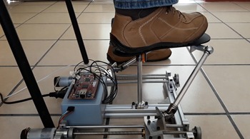
The physical prototype is shown in Fig. 12. The actuator’s position is measured by a linear incremental encoder with a resolution of 150 pulses per millimeter. The mobile platform’s angular velocity is obtained by using an inertial measurement unit (MPU 6050), while the angular position and acceleration are estimated with numerical treatment of the velocity signal. The bandwidth of the system is a 1 ms, which is sufficient for a mechatronic system such as the one presented. The results of the designed controller implementation are shown in Figs. 13–16.
Physical prototype.

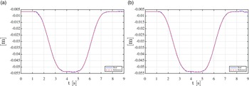
Experimental response to tracking the actuator position’s trajectory: (a) actuator 1 position and (b) actuator 2 position.

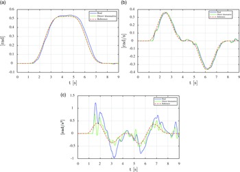
The platform trajectory tracking response for flexion/extension movement: (a) comparison of physical prototype, direct kinematics, and reference for actuators’ angular position, (b) comparison of physical prototype, direct kinematics, and reference for actuators’ angular velocity, and (c) comparison of actual, direct kinematics, and reference for actuators’ angular acceleration.

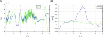
Dynamics of error tracking using a physical prototype: (a) tracking error dynamic for two actuators and (b) mobile platform position on X and Y axes.

Tracking of trajectory: (a) mobile platform trajectory tracking for abduction movements and (b) mobile platform trajectory tracking for eversion movements.

In Fig. 13, the trajectory tracking for the actuators is shown. The response of the two actuators has a small variation at 8 s because actuator two shows a small perturbation.
Figure 14 presents the flexion/extension movement of the parallel robot’s mobile platform. A flexion movement test was performed on a healthy adult, while the parameters for the desired trajectory, based on Eq. (40), were used for the flexion/extension motion:
 $\bar \psi _x$
= 0 rad (initial value) and
 $\bar \psi _x\,f$
= 0.523599 rad (final value) in the time interval t = [1.25 s, 4.25 s]. For the interval t = [4.25 s, 7.25 s], this movement starts at
 $\bar \psi _x$
= 0.523599 rad and ends at
 $\bar \psi _x\,f$
= 0 rad. In the bibliography consulted [Reference Magadán, Blanco, Gama and Abúndez11, Reference Chen, Zhou, Vanderborght, Wang and Wang12, Reference Qingsong, Chengxiang, Jie, Meng, Liu, Xie and Yang17], in order to begin to see a response from the control implemented in the ankle rehabilitators, an approximate time period of between 0 and 20 s was used. In Fig. 15, the tracking error dynamics for the actuators’ and mobile platforms’ positions are shown. The maximum absolute error can be appreciated at 5 ×
 $10^{-4}$
m for the actuator’s position (see Fig. 15a) and 0.0575959 rad for the robot mobile platform orientation (see Fig. 15b). The controller and the observer minimize the trajectory tracking error even when external disturbances are applied to the robot. In Fig. 16, the mobile platform trajectory tracking is shown for abduction (see Fig. 16a) and eversion (see Fig. 16b) movements. The discrepancy between the values calculated by direct kinematics and the real values measured at specific time intervals are due to the effect of a small mechanical defect in one of the couplers, which is detected and measured by the estimator. Despite this, however, the system follows the desired behavior in the eversion movement, without causing any problems for the user.
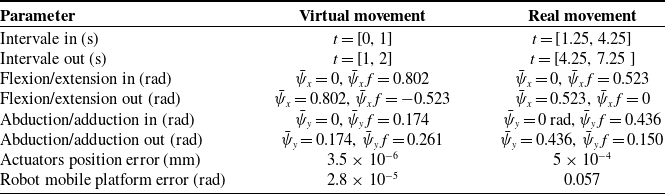
In the physical prototype, the actuators present a tracking error of less than 1 mm which is not significant for the movement to be performed by the parallel robot. The mobile platform presents a tracking error between the value estimated by the inertial measurement unit and the desired trajectory of less than 0.0610865 rad, which does not have an effect on the parallel robot’s performance. Considering the values calculated by direct kinematics [Reference Flores-Salazar, Arias-Montiel, Lugo-González, Gallardo-Alvarado, Tapia Herrera and Uhl22, Reference Flores-Salazar, Garcí-Murillo, Lugo-González, Gallardo-Alvarado, Arias-Montiel, Barrangan-Mendoza, Palafox-Delgado and Santiago Santos23], the tracking error is less than 0.003839724 rad (half a degree). Table II shows an abstract of results for virtual and real movements of the parallel robot. A difference between the values for the virtual and real prototypes can be observed due to the measurement instruments and users’ characteristics who performed the tests with the prototype. In both cases, the controller and the observer minimize the trajectory tracking error even when external disturbances are applied to the robot.
Results for the virtual and physical movements with the controller and the observer implemented.

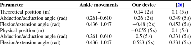
In order to verify the results, the research by Blanco-Ortega A. et al. [Reference Blanco, Gomez, Vela and Delgado26] was used, and the design and implementation of a generalized proportional integral (GPI) controller for ankle rehabilitation based on an XY table was shown. The horizontal linear guide provides the abduction/adduction motion, and the vertical linear guide provides the dorsiflexion/plantarflexion motion. As mentioned above, the same values were used to obtain the trajectory through the Bézier polynomial. In Table III, the positions of the mobile platform as well as the error and the angles generated during the abduction/adduction and flexion/extension movements were compared.
Comparison with different ankle rehabilitators.

A GPI controller and backstepping technique using an ESO (as presented in this article) can be observed when using the same values for the Bézier polynomial, on [Reference Blanco, Gomez, Vela and Delgado26], but with different control systems. It can also be seen that the theoretical results cannot be compared at all by the tests times, as they differ, with this study measuring 2 s and other studies measuring 5 s. The difference in times is due to which moment initiates the stability in each system. It can also be observed that theoretically the [Reference Blanco, Gomez, Vela and Delgado26] work presents a better theoretical response compared to the ankle movement angles, for example in flexion/extension, 0.436 rad [Reference Blanco, Gomez, Vela and Delgado26] and 0.456 rad ankle movements. The physical prototype presented in this work provides more accurate results compared to the ankle motion, for example in flexion/extension, 0.436 rad (our project) and 0.523 rad (ankle motion). The practical results presented by this research are within the ankle’s range of motion.
7. Conclusion
Considering the parallel robot as a highly nonlinear system, the use of inverse kinematics facilitates the obtention of a set of linear differential equations that are solved using a decentralized control scheme based on the backstepping technique and linear ESO. In this work, the aforementioned control system was used to solve the trajectory tracking problem and estimate the structured and unstructured uncertainties presented by the robot. The proposed controller-observer scheme solves the tracking problem for the parallel ankle rehabilitation robot with the use of the active disturbance rejection control paradigm. Furthermore, a decentralized ADRC is used for each prismatic actuator, while the system’s closed-loop performance is initially tested using a MATLAB-ADAMS cosimulation. The numerical results obtained show a satisfactory tracking of the mobile platform’s trajectory performing specific rehabilitation movements. This is in addition to achieving system stability in a realistically short time (2 s for the virtual prototype and 5 s for the physical prototype), which demonstrates the feasibility of the proposed controller to be implemented in the physical prototype for ankle rehabilitation. As observed in Table III, the physical prototype presented has the ability to comply with the specific trajectories for flexion/extension and abduction/adduction, as well as being a device that can be validated with the results of other studies and specific ankle movements. The mobile platform presents a tracking error between the value estimated by the inertial measurement unit and the desired trajectory of less than 0.061 rad, which also has no effect on the parallel robot’s performance. A proposal for future work would be to use other methods of advanced control to minimize the errors in the trajectory tracking and to perform a more extensive verification and validation with other works related to this topic, as well as seeking approval for its use by specialized personnel in physical rehabilitation.
Author contributions
Erick. D. Flores-Salazar and Esther Lugo-González conceived and designed the study. Jaime Gallardo-Alvarado, Manuel Arias-Montiel and Erick. D. Flores-Salazar performed statical and dynamical analyses. Manuel Arias-Montiel, Erick. D. Flores-Salazar and Esther Lugo-González developed the control system. Erick. D. Flores-Salazar implemented a control system. Erick. D. Flores-Salazar and Esther Lugo-González wrote the article.
Financial support
This research received no specific grant from any funding agency, commercial or not-for-profit sectors.
Competing interests
The authors declare no competing interests exist.
Ethical approval
Not applicable.