


Impact Statement
Membrane separation technologies are crucial for increasing the selectivity and energy efficiency of chemical separations. Membranes can also enable novel separations that are difficult to achieve via traditional techniques, such as the recovery of critical minerals from wastewater and brine. However, emerging membrane technologies face challenges in scaling up membrane materials from the lab to industry. This work presents a proof of concept for scaling up phyllosilicate-based membranes, a novel class of inorganic membranes with many advantages, including low cost, tunable structure, and environmental compatibility. We used slot-die coating (including both batch-scale and continuous roll-to-roll methods) to fabricate large-area phyllosilicate membranes on top of nylon substrates. The coated membranes are 1–2
$ \unicode{x03BC} \mathrm{m} $
 in thickness and exhibit similar structure and performance to membranes fabricated at the lab scale. The methods and findings from this work will accelerate the implementation of phyllosilicate and other 2D-material-based membranes in industry. This transition will enable new and more selective commercial separations while leveraging these materials’ extremely low cost and environmental friendliness. Ultimately, the scalable fabrication of phyllosilicate nanofiltration membranes will address the global challenge of critical mineral recovery while also improving the energy efficiency of chemical separations.
1. Introduction
Membrane technologies play a central role in enabling energy-efficient chemical separations and the recovery of critical minerals. Membrane separations have several advantages over traditional thermal separation techniques (e.g., distillation), including low energy consumption, high efficiency for many separations, and the ability to be operated continuously [Reference Baker1, Reference Taylor and Jacobs2, Reference Lee, Elam and Darling3]. While membranes have been in use for decades in aqueous separation applications, such as desalination and water purification, another growing area of interest is the selective recovery of critical minerals from wastewater and brine. Specifically, metals including lithium, transition metals such as cobalt, and rare earth elements are in high demand for energy technologies but have low rates of recycling and are challenging to mine [Reference Sholl and Lively4, Reference DuChanois, Cooper and Lee5]. These metals are present in dilute concentrations in many aqueous sources; for example, water contains over 70% of the total recoverable lithium on Earth [Reference DuChanois, Cooper and Lee5, Reference Swain6, Reference Quinby-Hunt and Turekian7, Reference Darling8]. Recovering lithium and other valuable metals from industrial waste streams, brines, or seawater is an attractive prospect for improving energy security. Size- or charge-based separation (nanofiltration) of these metals from other ions in complex aqueous sources is thus an important research goal.
Two-dimensional (2D) materials, a broad class of crystalline materials, have experienced a research boom since the discovery of graphene in 2004. These materials consist of exfoliated, atomically thin sheets that can be stacked into layered or lamellar structures. A layered 2D material’s structure consists of many 2D flakes separated by ordered interlayer spaces approximately 1 nm in size [Reference Choi, Yun and Won9, Reference Wang, Xiong and Wang10]. These interlayer spaces, or nanochannels, make 2D materials attractive for size-based ion separations (as hydrated ions also have diameters of the order of 1 nm). Furthermore, the size of the interlayer spaces can be tuned by modifying the ion species and amount of water present in the interlayer [Reference Gao, Sun and Poorandokht11, Reference Osti, Naguib and Ostadhossein12, Reference Wang, Wang and Gu13, Reference Zhu, Booth and Eatman14] or by selecting crosslinking agents of varying dimensions, allowing for highly selective separations. Recent research has shown that partial desolvation of ions may also occur during nanoconfinement in the interlayer spaces of 2D materials [Reference Ghidiu, Halim and Kota15, Reference Li, Wang and Liu16], contributing to selectivity; however, thorough characterization and modeling of ion solvation under confinement remain an open research topic [Reference Zhao, Liu, Hao, Zhao and Zhou17]. Graphene oxide [Reference Li, Li, Xia, Yuan and Zhang18], MXenes [Reference Booth, Xiong, Jeon, Schatz and Hatzell19, Reference Ventura-Martinez, Zhu, Booth and Hatzell20, Reference Ding, Li and Liu21], and transition metal dichalcogenides (TMDCs) [Reference Wang, Xiong and Wang10, Reference Xiong, Liu and Schatz22] are various types of 2D materials that can be processed into layered nanofiltration membranes.
Phyllosilicates are a diverse family of naturally occurring clay minerals that also belong to the class of 2D materials. Phyllosilicates have a stacked–sheet-like structure formed by tetrahedral and octahedral layers. For example, vermiculite (VM), Mg0.7(Mg,Fe,Al)6(Si,Al)8O20(OH)4•8H2O, consists of Mg- or Fe-based octahedral sheets sandwiched between tetrahedral silicate sheets. While these natural materials have long been used in traditional industries such as construction [Reference Liu, Wang and Sengupta23, Reference Xia, Chen and Shevate24, Reference Tian, Wang and Wang25], they have recently drawn attention as candidate materials for nanofiltration membranes [Reference Huang, Rowe and Chi26, Reference Tian, Liu and Zhang27, Reference Liu, Tan and Qian28, Reference Wang, Hao and Yan29]. Similar to other 2D materials, phyllosilicates have demonstrated selectivity for monovalent over multivalent cations due to a combination of size and charge (Donnan) exclusion [Reference Liu, Wang and Sengupta23, Reference Xia, Chen and Shevate24]. However, phyllosilicates possess several advantages over synthetic 2D materials, including their abundance and very low cost (e.g., VM has a price of around $350 per ton). Additionally, phyllosilicates are environmentally stable, have highly tunable interlayer spacing, and are amenable to mild membrane synthesis routes [Reference Ra, Kim, Kim, Bae and Shim30, Reference Kim, Liu, Booth, Hatzell and Darling31]. These advantages in cost, properties, and environmental friendliness make phyllosilicates competitive membrane materials compared to materials such as MXenes and TMDCs, which often have expensive precursors and require strong acids or organic solvents to synthesize.
Scalable fabrication of phyllosilicate membranes will be critical for adapting these novel membranes to industrial applications. While phyllosilicate and other 2D-material-based membranes have attractive properties for molecular-scale separations, they are typically fabricated at the lab scale, using slow and small-batch processes such as vacuum filtration. This is a major bottleneck limiting their adoption in industry, where large membrane surface areas are required to construct membrane modules and achieve high production rates. Recently, 2D materials such as graphene, MXenes, and molybdenum disulfide have been fabricated into large-area membranes using batch-scale slot-die coating [Reference Kim, Choi and Kang32, Reference Guo, Zhou and Gao33, Reference Kim, Park and Kim34, Reference Kim, Jung and Choi35] and roll-to-roll coating [Reference Esfahani, Ma, Flewellen, Nair and Harris36, Reference Li, Liu and Shi37, Reference Lim, Han and Kim38, Reference Wells, Johnson, Lhermitte, Kinge and Sivula39]. Slot-die coating is a process that injects a coating ink into a die head, which spreads the ink across a substrate to form a flat-sheet thin film or membrane. This method can be integrated into a roll-to-roll process in which the ink continuously coats a moving substrate fed from a long roll. In this work, we present slot-die and roll-to-roll methods for fabricating VM membranes (with ethylenediamine–vermiculite crosslinkers (EDAVM) as an exemplar). The large-area membranes are 1–2
$ \unicode{x03BC} \mathrm{m} $
 in thickness, thinner than previously reported freestanding VM membranes [Reference Liu, Wang and Sengupta23, Reference Xia, Chen and Shevate24], but show the same lamellar structure and similar ion transport performance. This work is a proof of concept for scalable coating methods that can bring these low-cost, stable, and tunable membrane materials to industry.
2. Methods and Materials
2.1. Materials
Bulk raw VM particles, lithium chloride (LiCl), sodium chloride (NaCl), potassium chloride, calcium chloride, and ethylenediamine (EDA) were purchased from Sigma-Aldrich and used as received. Nylon membranes (0.22
$ \unicode{x03BC} \mathrm{m} $
 pore size) were purchased from Tisch Scientific as 30 cm × 3 m rolls.
2.2. Preparation of Aqueous Vermiculite Dispersion
A stable aqueous dispersion of exfoliated VM flakes was prepared via two steps of ion exchange. In total, 2.2 g of raw VM (Supplementary Figure 1S) was added to 500 mL of saturated (6 M) NaCl in water and stirred at 99°C for 24 h. The next day, the solution was vacuum-filtered through a porous polyvinylidene fluoride (PVDF) filter to obtain the NaCl-exchanged VM particles. The particles were rinsed with 20 mL of deionized (DI) water. Next, the NaCl-exchanged VM particles were added to 500 mL of 2 M LiCl and stirred at 99°C for 24 h. The LiCl-exchanged particles were also collected via vacuum filtration, then rinsed twice with 20 mL of DI water.
The collected LiCl-exchanged VM was diluted with 250 mL of DI water and sonicated for 1 h in a large glass beaker. Sonication was performed on low power to exfoliate flakes while avoiding excessive damage (e.g., reduction in lateral size of flakes). The sonicated dispersion was diluted again, to a total of 1 L, and stored.
The dilute ∼2 g L−1 VM dispersion was centrifuged at 2000 rpm for 10 min to achieve size selection. A yellow-colored supernatant, composed of single-layer exfoliated VM flakes (Supplementary Figure 1S), was collected. The unexfoliated sediment was discarded. Then, the yellow-colored solution was centrifuged at 9500 rpm for 1 h to concentrate the VM flakes. The clear supernatant was discarded, and a dark-colored sediment was collected and redispersed in a small amount of DI water to achieve a concentration of ∼35 g L−1.
2.3. Slot-Die and Roll-to-Roll Coating
The VM dispersion was used to prepare the slot-die coating solution. The concentrated single-layer VM was diluted to 20 g L−1, and 0.5% (volume percent) liquid EDA was added as a crosslinker. Higher concentrations of EDA can cause undesirable aggregation in solution (see Section 3 and Supplementary Figure 2S for more details). The solution was mixed by hand and with a vortex mixer, then transferred to a 5-mL syringe for coating.
Slot-die coating was performed using an Ossila slot-die coater with built-in syringe pump. The substrate was a flat-sheet nylon membrane cut to ∼10 cm × 20 cm and adhered to a glass plate. The VM dispersion was injected through the coater head to form a meniscus, and then the substrate was moved at constant speed while the syringe injection continued. After coating was complete, the nylon substrate was removed from the glass, and the membrane was oven-dried at 80°C overnight (at least 12 h). More details of the process are reported in Section 3.
Roll-to-roll coating was performed using a roll-to-roll coating apparatus (FOM photonR2R, FOM Technologies, Kastrup, Denmark). The roll-to-roll coating trials were conducted at the Materials Engineering Research Facility of Argonne National Laboratory. The same VM dispersion and syringe injection method was used for roll-to-roll and batch slot-die coating. Coating was performed on a rolled nylon substrate cut to 2.5 cm in width. The substrate was gradually uncoiled and was pulled with 9 N of tension past the slot-die head as the VM dispersion was applied. After the VM was deposited, in-line heating chucks were used to dry the membrane at 80°C for approximately 30 min as the substrate moved along the length of the coating apparatus. After in-line drying, the membrane was immediately coiled onto a second roll. The rolled membrane was then removed and oven-dried at 80°C for at least 12 h.
2.4. Structural and Performance Characterization
X-ray diffraction (XRD) patterns were obtained using a Rigaku benchtop X-ray diffractometer equipped with HyPix-400 MF 2D hybrid pixel array detector (HPAD) and a Cu K
$ \alpha $
 X-ray source (wavelength of 1.5418 Å), operating with the Bragg–Brentano geometry at 40 kV and 15 mA. Each XRD spectrum was averaged from two duplicate samples. Cross-sectional images of the VM membranes were obtained using scanning electron microscopy (SEM) at the Center for Nanoscale Materials, Argonne National Laboratory. Profilometry was performed on freestanding membrane samples. Samples were prepared by immersing a membrane in water, mechanically removing the VM from the substrate, then transferring onto a Si wafer.
Vermiculite dispersions (coating inks) were rheologically studied using a DHR3 hybrid rheometer (TA Instruments, USA). All dispersions were studied using a parallel plate geometry with 1000
$ \unicode{x03BC} \mathrm{m} $
 gap thickness. Shear sweeps were run from 200 s−1 to 0.01 s−1 at 25°C and ambient pressure.
Membrane performance characterization was conducted using machined diffusion cells. Membranes were sandwiched between watertight feed and permeate compartments using a screw-based assembly. In total, 30 mL of DI water was added to the permeate compartment, and 20 mL of 0.1 M salt solution was added to the feed compartment. In the case of binary (multi-ion) measurements, the feed solution was an equimolar mixture of both salts at 0.05 M each. A 1 mL aliquot was taken from the permeate at 2 h, 4 h, 6 h, and 24 h, and the salt concentration was analyzed using inductively coupled plasma optical emission spectroscopy (Agilent ICP-OES).
3. Results and Discussion
3.1. Lab-Scale Slot-Die Coating of Vermiculite Membranes
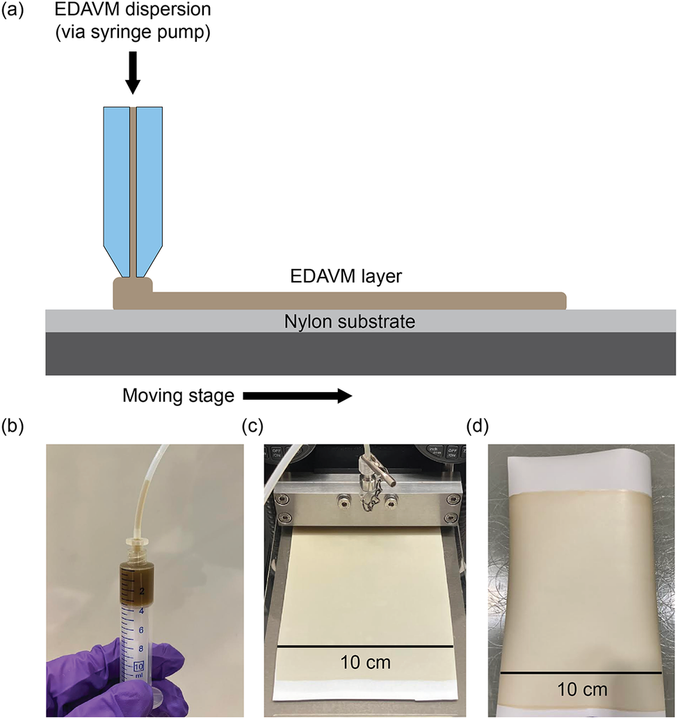
Slot-die coating is widely used to deposit thin films across a range of applications in energy storage, energy conversion, and membrane technologies. This technique relies on the generation of a controlled pressure gradient to drive a fluid through a shim and dispense it onto a moving substrate (Figure 1a). The rheological properties of the fluid, along with the shear rate at the die exit, play a critical role in achieving uniform, defect-free membranes. Herein, we investigate the slot-die processing of an “ink” composed of EDA and VM (EDAVM). Ethylenediamine, C2H4(NH2)2, is a diamine linker known to promote water stability in VM membranes [Reference Xia, Chen and Shevate24]. EDA was selected because it has the shortest chain length of all diamine linkers compatible with VM and is thus the least susceptible to aggregation. Aggregation of VM flakes occurs with excess linker concentration, especially for longer-chain linkers, and causes solid aggregates to precipitate out of solution. These aggregates are detrimental to slot-die coating because they can cause heterogeneity in the coated film and/or clog the slot die head (Supplementary Figure 2S).
(a) Schematic of the slot-die coating process. Images of (b) the ethylenediamine-vermiculite (EDAVM) coating solution, (c) slot-die coating of EDAVM onto a flat-sheet nylon substrate, and (d) a slot-die coated membrane after drying.

Figure 1. Long description
The graphic is divided into four panels labeled a through d.
* Panel a is a schematic diagram of the slot-die coating process. At the top, a black arrow points down to a blue slot-die head, labeled E D A V M dispersion via syringe pump. The dispersion flows through the die onto a light gray Nylon substrate. The resulting brown E D A V M layer is shown spreading to the right. Below the substrate is a dark gray moving stage with a black arrow pointing to the right.
* Panel b is a photo of a gloved hand holding a syringe filled with a dark brown E D A V M coating solution. A thin tube connects the top of the syringe to the coating apparatus.
* Panel c is a photo showing the slot-die coating of E D A V M onto a flat-sheet nylon substrate. A wide metal die head is depositing a uniform beige layer onto the white substrate. A black scale bar at the bottom indicates a width of 10 c m.
* Panel d is a photo of the finished slot-die coated membrane after drying. The membrane is a large, flexible rectangular sheet with a uniform beige coating. A black scale bar at the bottom indicates a width of 10 c m.
Slot-die coating was performed using an Ossila brand slot die coater. The coating solution was loaded into a syringe (Figure 1b) and injected into the slot-die head to form a meniscus. Once the meniscus had spread across the full width of the substrate, a program was executed to move the stage at constant speed while injecting the coating solution at a constant rate (linear feed system). This process formed a thin VM film of constant thickness on top of the substrate (Figure 1c), which was air-dried for 1 h and then dried in an oven at 80°C overnight to produce a dry VM membrane (Figure 1d).
The substrate material was a flat sheet of porous nylon (polyamide) approximately 130
$ \unicode{x03BC} \mathrm{m} $
 thick. To ensure the substrate was flat with no wrinkles, we adhered the nylon to a glass plate by wetting the top of the glass plate, placing the nylon on top, and drying at 80°C for 1 h before coating. After coating, the VM–nylon membrane was removed from the glass plate.
We performed initial test runs of slot-die coating using a dispersion of pure VM with no crosslinker. We prepared the VM dispersion with a concentration of 20 g L−1, similar to concentrations used in other 2D material coating studies [Reference Guo, Zhou and Gao33, Reference Kim, Park and Kim34]. We set the shim thickness (i.e., interior gap inside the slot-die head) to 500
$ \unicode{x03BC} \mathrm{m} $
 with a shim width of 100 mm, as we found that smaller gaps could allow solid VM particles to clog the head. We set the gap height (i.e., distance between slot-die head and substrate) to 300
$ \unicode{x03BC} \mathrm{m} $
 . This gap height allowed the meniscus to quickly spread laterally across the entire width of the nylon sheet membrane; larger gap heights caused the meniscus to bulge (expand axially) near the center of the membrane without spreading. We adjusted the coating length to 12 cm to fit the size of the nylon sheet membranes.
We set the stage movement speed at 1.0 mm s−1, which allowed a 12-cm-long membrane to be coated in 2 min. We chose this speed to maximize the amount of VM deposited from the meniscus in a single coating. Speeds lower than 1.0 mm s−1 caused liquid to accumulate on top of the nylon substrate, which resulted in the coffee-ring effect (slow drying) and caused heterogeneity in the membrane [Reference Deegan, Bakajin and Dupont40]. Faster speeds allowed less VM to be deposited, resulting in sub-1-
$ \unicode{x03BC} \mathrm{m} $
 membranes. We set the syringe injection rate at 15 μL s–1. This injection rate allowed the meniscus to maintain a constant width during coating, without overflowing or becoming depleted. The selected coating speed, injection rate, and gap height were also chosen to give a wet film thickness of 150
$ \unicode{x03BC} \mathrm{m} $
 according to Eq. 1:

where
$ {Q}_{pump} $
 is the pump injection rate (15 μL s–1 = 900 μL min–1),
$ {v}_{stage} $
 is the stage movement speed (0.06 m min−1), and
$ {w}_{coating} $
 is the coating width (0.1 m). The wet film thickness is much larger than the true dry membrane thickness of 1–2
$ \unicode{x03BC} \mathrm{m} $
 , as the oven-drying process removes most of the wet film’s volume.
After determining the coating parameters for pure VM, an EDAVM dispersion was prepared by combining 0.5% (by volume) liquid EDA with a 20 g L−1 aqueous dispersion of VM flakes. This EDA concentration was chosen to promote the formation of water-resilient membranes while limiting VM aggregation in solution. At lower concentrations of EDA, the membrane was opaque and disintegrated in water, while at higher concentrations, VM aggregates formed and the membrane became heterogeneous (Supplementary Figure 2S). Simple water stability tests were conducted by soaking membranes in water for 24 h and then observing whether the membranes could be removed from water without tearing. EDAVM was coated onto nylon substrates using the above parameters, producing flat-sheet EDAVM membranes approximately 10 cm × 12 cm in size.
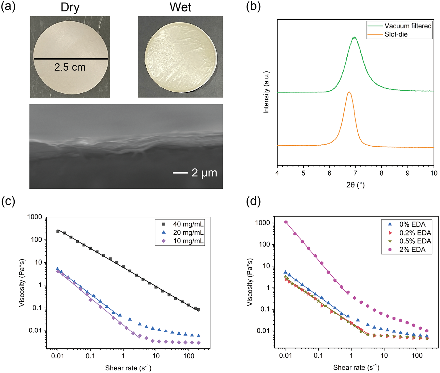
Each flat-sheet membrane was punched into approximately 12 smaller circular membranes, with a diameter of 2.5 cm (Figure 2a), for further testing. Upon wetting, the membranes separated slightly from the nylon substrate but retained their structural integrity. Cross-sectional SEM images indicate that the slot-die coated VM membranes were approximately 1–2
$ \unicode{x03BC} \mathrm{m} $
 in thickness (Figure 2a). XRD results (Figure 2b) indicate that the slot-die coated EDAVM had a slightly larger d-spacing than previously reported EDAVM fabricated via vacuum filtration (13.1 Å versus 12.7 Å). Vacuum filtration, a small-batch technique for fabricating 2D-material-based membranes, is the typical procedure for producing VM membranes and is reported in detail in our past work [Reference Xia, Chen and Shevate24]. The slight structural discrepancy between the two fabrication methods may occur because vacuum filtration can more effectively compress or remove water from the stacked VM layers.
(a) Optical images of 2.5-cm ethylenediamine–vermiculite (EDAVM) membranes in the dry state and after 24 h of soaking in water; cross-sectional SEM image of slot-die coated EDAVM. (b) X-ray diffraction spectra for slot-die coated and vacuum-filtered EDAVM membranes. Vacuum-filtered data adapted from Xia et al. [Reference Xia, Chen and Shevate24] (c) Viscosity as a function of shear rate for 10 mg mL−1, 20 mg mL−1, and 40 mg mL−1 dispersions of pure vermiculite in water. (d) Viscosity as a function of the shear rate for 20 mg mL−1 vermiculite dispersions with 0%–2% EDA linker.

Figure 2. Long description
Panel a contains three photos. Top left shows a circular beige Dry membrane with a 2.5 cm scale bar. Top right shows a Wet membrane with a slightly wrinkled texture. Below these is a cross-sectional S E M photo showing a layered, sheet-like structure with a 2 micrometer scale bar.
Panel b is an X R D spectrum with x-axis 2 theta in degrees from 4 to 10 and y-axis Intensity in arbitrary units. Two curves are shown: a green Vacuum filtered curve on top and an orange Slot-die curve below. Both exhibit a single prominent peak centered at approximately 7 degrees.
Panel c is a log-log line graph of Viscosity in Pascal-seconds versus Shear rate in reciprocal seconds. Three datasets are plotted: 40 mg per m L (black squares), 20 mg per m L (blue triangles), and 10 mg per m L (purple diamonds). The 40 mg per m L curve shows a linear decrease across the entire range. The lower concentration curves decrease linearly until a shear rate of 1, where they plateau.
Panel d is a log-log line graph of Viscosity versus Shear rate for 20 mg per m L dispersions with varying E D A linker percentages: 0 percent (blue triangles), 0.2 percent (red triangles), 0.5 percent (gold stars), and 2 percent (pink circles). The 2 percent E D A curve maintains significantly higher viscosity across all shear rates compared to the other three, which follow a similar downward trend and plateau.
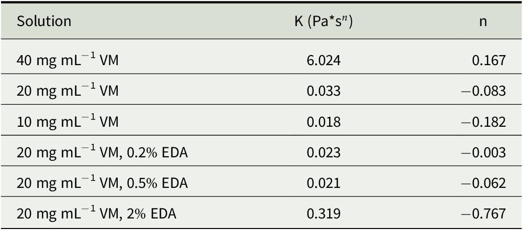
The quality of the coated wet film and organization of VM particles in the dry film depends on the rheology of the coating solution (ink). In particular, the variation of ink viscosity with the shear rate is an important characteristic for assessing coating behavior and interparticle interactions [Reference Tadros41, Reference Somalu, Muchtar, Daud and Brandon42]. Figure 2c, d illustrate the viscosity–shear behavior of VM coating solutions with different VM and EDA concentrations. All solutions exhibit shear-thinning behavior between 0 and 200 s−1, which is beneficial for coating and indicates the formation of layers of particles in the ink phase coincident to the shear plane [Reference Dixit, Harkey, Shen and Hatzell43, Reference Bisht, Dixit and Essehli44]. Viscosity behavior in the shear-thinning (non-Newtonian) region can be described by a power law model (Eq. 2) [Reference Macosko45]:

where
$ \eta $
 is the viscosity (Pa*s),
$ K $
 is the flow consistency index (Pa*s
$ {}^n $
 ),
$ \dot{\gamma} $
 is the shear rate (s−1), and
$ n $
 is the unitless power law constant. Table 1 presents the power law parameters for the various VM solutions. In Figure 2c, d, power law fits are displayed alongside the experimental data in the applicable non-Newtonian (i.e., constant slope) regions.
Power law parameters for the various VM and EDAVM solutions within the non-Newtonian region.

Table 1. Long description
The table consists of three columns: Solution, K (measured in Pascal seconds to the n power), and n.
* Row 1: 40 mg m L super minus 1 V M; K is 6.024; n is 0.167.
* Row 2: 20 mg m L super minus 1 V M; K is 0.033; n is minus 0.083.
* Row 3: 10 mg m L super minus 1 V M; K is 0.018; n is minus 0.182.
* Row 4: 20 mg m L super minus 1 V M, 0.2 percent E D A; K is 0.023; n is minus 0.003.
* Row 5: 20 mg m L super minus 1 V M, 0.5 percent E D A; K is 0.021; n is minus 0.062.
* Row 6: 20 mg m L super minus 1 V M, 2 percent E D A; K is 0.319; n is minus 0.767.
Dilute solutions of VM exhibit lower viscosity than concentrated solutions. The viscosity of 40 mg mL−1 VM is over an order of magnitude higher than that of 20 mg mL−1 VM (Figure 2c). This result indicates that the 20 mg mL−1 VM solution has improved particle dispersion and reduced interparticle interactions. However, the reduction in viscosity diminishes with further dilution (i.e., the 10 mg mL−1 and 20 mg mL−1 solutions have similar viscosity), so there is little benefit to diluting the solution below 20 mg mL−1. At high shear rates, the 20 mg mL−1 and 10 mg mL−1 solutions deviate from power law behavior and approach constant viscosity. This result indicates that dilute VM coating solutions are approximately Newtonian (the effect of particle–particle interactions on flow behavior is negligible) at high shear rates.
Adding EDA linker to the VM coating solution can influence the rheological behavior of the ink. When a small amount of EDA (0.2%–0.5% v/v) is added to a 20 mg mL−1 vermiculite dispersion, the solution’s viscosity slightly decreases (Figure 2d). The solution also approaches a constant viscosity (reaches Newtonian behavior) at a relatively low shear rate of 3–4 s−1. This effect may occur because EDA improves the ordering of VM flakes and allows them to easily move parallel to the shear plane or possibly because excess EDA molecules can act as a lubricant to reduce VM particle interactions. However, when the EDA concentration increases to 2%, the solution’s viscosity greatly increases. This result indicates the formation of undesirable VM aggregates at high linker concentrations.
The shear rate during slot-die coating can be estimated according to Eq. 3:

where
$ v $
 is the substrate movement speed and
$ h $
 is the gap height [Reference Khandavalli and Rothstein46]. For both batch slot-die coating and roll-to-roll coating, a substrate speed of 1 mm s−1 and a gap height of 300
$ \unicode{x03BC} \mathrm{m} $
 (0.3 mm) were used. Therefore, the approximate shear rate for both coating protocols was 3.3 s−1. This shear rate is at the low end of the Newtonian (constant-viscosity) regime for VM with 0.5% EDA; the presence of EDA contributes to reduced ink viscosity at this shear rate.
3.2. Ion Separation Performance of Slot-Die Coated Membranes
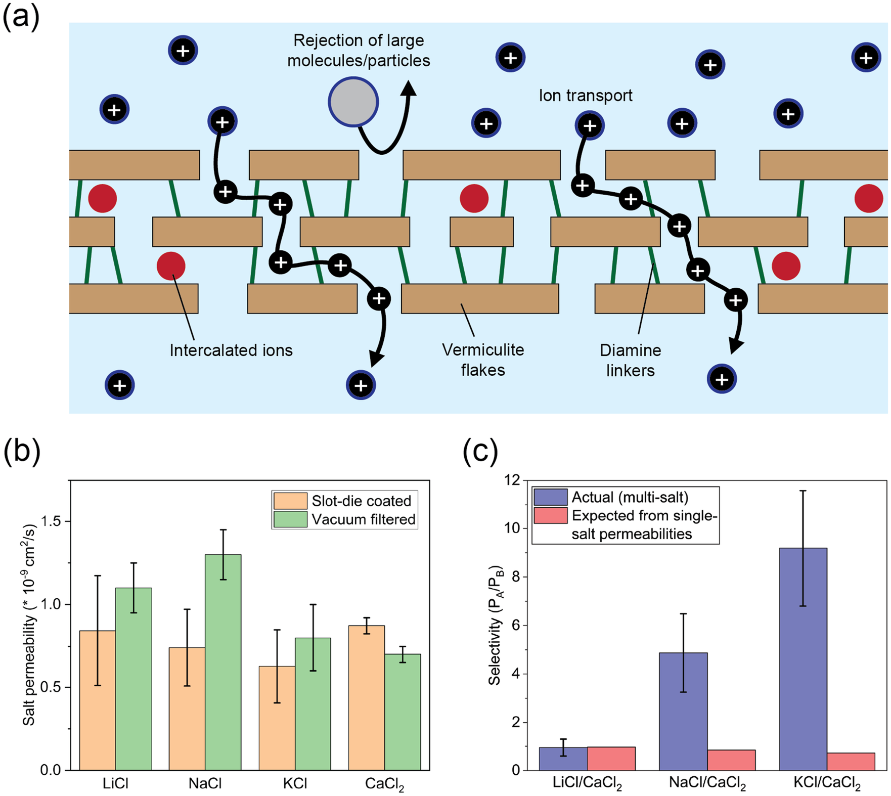
Vermiculite-based membranes are attractive candidates for charge- and size-selective ion separations (Figure 3a), and scalable fabrication will help adapt these membranes to industrial applications. We used lab-scale diffusion testing to conduct an initial investigation of these slot-die coated membranes’ ion separation capabilities. The 2.5-cm membranes were loaded into homemade diffusion cells, which used a screw/gasket assembly to sandwich a membrane between the feed solution and permeate solution. The cells were lightly stirred for 24 h to reduce concentration polarization, and the permeate was sampled for ICP analysis to determine ion concentration.
(a) Schematic of ion transport through a layered vermiculite (VM) membrane. (b) Single-salt permeability comparison (LiCl, NaCl, KCl, and CaCl2) between slot-die coated ethylenediamine–vermiculite (EDAVM) and vacuum-filtered EDAVM. Vacuum filtration data were adapted from Xia et al. [Reference Xia, Chen and Shevate24] (c) Measured multisalt selectivity of three equimolar binary salt mixtures (LiCl/CaCl2, NaCl/CaCl2, and KCl/CaCl2) through slot-die–coated EDAVM, compared with the expected selectivity from single-salt permeability ratios.

Figure 3. Long description
Panel a is a schematic cross-section. At the top, a blue solution contains small black circles with plus signs representing ions and a large grey circle representing a molecule. A curved arrow shows the large molecule being rejected by the membrane surface. Black paths with plus signs show ion transport through a layered structure of brown rectangles labeled Vermiculite flakes. The flakes are connected by vertical green lines labeled Diamine linkers. Red circles between layers are labeled Intercalated ions. Ions exit the bottom of the membrane into another blue solution layer.
Panel b is a bar graph of Salt permeability in units of 10 super minus 9 centimeters squared per second. The x-axis lists L i C l, N a C l, K C l, and C a C l sub 2. For each salt, two bars are shown: orange for Slot-die coated and green for Vacuum filtered. For L i C l, N a C l, and K C l, vacuum filtered permeability is higher than slot-die coated. For C a C l sub 2, slot-die coated is slightly higher.
Panel c is a bar graph of Selectivity P sub A forward slash P sub B. The x-axis lists three binary mixtures: L i C l forward slash C a C l sub 2, N a C l forward slash C a C l sub 2, and K C l forward slash C a C l sub 2. Blue bars represent Actual multi-salt data and red bars represent Expected from single-salt permeabilities. The actual selectivity for N a C l and K C l mixtures is significantly higher than expected, reaching approximately 5 and 9 respectively, while the expected values remain near 1.
Membranes were first tested with 0.1 M feed solutions of single salts (LiCl, NaCl, KCl, and CaCl2). This library of salts was chosen to compare the membranes’ permeability for three different monovalent ions (Li+, Na+, and K+) and to determine the effectiveness of separating these ions from a multivalent ion, Ca
$ {}^{2+} $
 . Each salt’s flux was calculated using Eq. 4:

where
$ {J}_i $
 represents the molar flux of species
$ i $
 ,
$ {C}_i $
 is the concentration of species
$ i $
 ,
$ V $
 is the cell volume,
$ A $
 is the membrane area in the cell, and
$ \Delta t $
 is the elapsed time. Data were inspected to ensure that the ion permeation trend was approximately linear over 24 h (i.e., the membrane did not fail).
Ion flux was converted to permeability using Eq. 5:

where
$ {P}_i $
 represents the permeability of species
$ i $
 ,
$ {J}_i $
 is the flux of species
$ i $
 from Eq. 4,
$ L $
 is the thickness of the membrane, and
$ {C}_{i, feed} $
 is the concentration of species
$ i $
 in the feed.
The slot-die–coated membranes show single-salt permeabilities within 1–2 standard errors of the vacuum-filtered membranes previously published [Reference Xia, Chen and Shevate24]. Specifically, monovalent ion permeabilities are slightly lower for the slot-die–coated membranes, while Ca
$ {}^{2+} $
 permeability is slightly higher. These slight discrepancies in permeability may arise from structural differences between the two types of membranes. Ion transport through membranes depends on both (a) bulk diffusion through the membrane material and (b) partitioning (i.e., ions entering/leaving the membrane at the water–membrane interface) [Reference Kingsbury, Baird and Zhang47]. Although permeability is normalized by membrane thickness, transport through the thin (1–2
$ \unicode{x03BC} \mathrm{m} $
 ) slot-die–coated membranes will depend more on partitioning effects, while bulk diffusion will be more important for the thicker (∼20
$ \unicode{x03BC} \mathrm{m} $
 ) vacuum-filtered membranes. The slightly different interlayer spacing of the two types of membranes, as well as differing amounts of water and ions remaining in the membranes after the two fabrication methods, may also affect permeability.
After determining each ion’s permeability, we measured the monovalent/multivalent selectivity of the EDAVM membranes via diffusion cell testing with equimolar mixtures of each pair of salts. In each case, the feed concentration was fixed at 0.05 M of each salt to keep a constant feed molarity of 0.1 M. The selectivity of each pair of cations was calculated by taking the ratio of both permeabilities (Eq. 6):

The selectivity was determined from these actual multisalt measurements and compared to the “pseudo-selectivity” expected from taking the ratio of each single-salt permeability (Figure 3c). Importantly, the true selectivity is always higher than the selectivity expected from single-salt experiments. This effect is most extreme for the KCl/CaCl2 separation, in which the measured selectivity is approximately 9.2 but the expected selectivity is less than 1. These results motivate the need to characterize membranes in realistic environments instead of making assumptions based on single-salt permeability testing. Future 2D-material membrane scale-up studies may benefit from using high-throughput testing to measure ion transport performance in various ionic environments.
3.3. Scalable Vermiculite Membrane Fabrication via Roll-to-Roll Coating
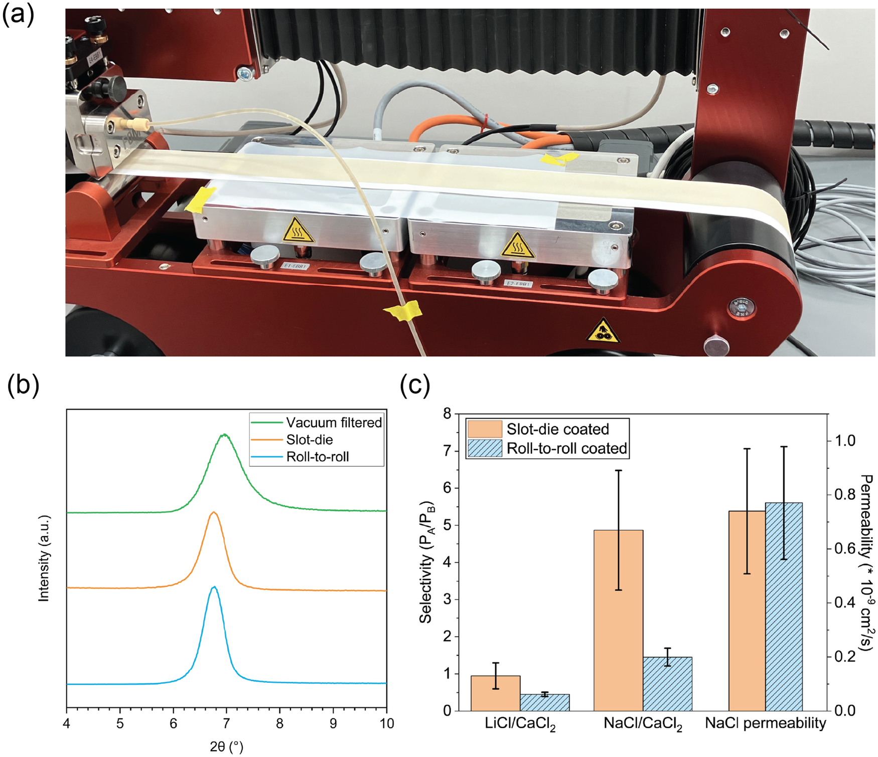
After characterizing the slot-die–coated membranes, we applied a roll-to-roll coating apparatus (Figure 4a) to further scale up EDAVM membrane fabrication. Roll-to-roll coating is a process for coating a wet film onto a long substrate; it differs from batch slot-die coating in that the head is stationary and coats onto a moving, spooled substrate. The substrate can thus have an indefinite length, making roll-to-roll coating a continuous process.
(a) Image of roll-to-roll coating of ethylenediamine–vermiculite (EDAVM) onto a nylon substrate. (b) X-ray diffraction comparison of roll-to-roll coated EDAVM, batch slot-die–coated EDAVM, and vacuum-filtered EDAVM. (c) Multi-ion selectivity and single-salt NaCl permeability comparison between roll-to-roll and batch slot-die–coated EDAVM.

Figure 4. Long description
Panel a is a photo of a red roll-to-roll coating machine. A white nylon substrate ribbon moves horizontally across two heated silver plates marked with yellow warning symbols. A thin tube feeds liquid onto the substrate at the left side.
Panel b is an X R D diffractogram. The x-axis is 2 theta in degrees from 4 to 10. The y-axis is Intensity in arbitrary units. Three stacked curves show a single prominent peak around 6.8 degrees. From top to bottom, the curves represent Vacuum filtered (green), Slot-die (orange), and Roll-to-roll (blue). The peaks are vertically aligned, indicating consistent interlayer spacing across methods.
Panel c is a bar chart comparing Slot-die coated (solid orange) and Roll-to-roll coated (blue diagonal stripes) E D A V M. The left y-axis is Selectivity (P sub A / P sub B) from 0 to 8. The right y-axis is Permeability (* 10 super minus 9 cm squared per second) from 0.0 to 1.0.
* For Li Cl / Ca Cl sub 2 selectivity, Slot-die is approximately 1.0 and Roll-to-roll is approximately 0.5.
* For Na Cl / Ca Cl sub 2 selectivity, Slot-die is approximately 4.9 and Roll-to-roll is approximately 1.5.
* For Na Cl permeability, Slot-die is approximately 0.75 and Roll-to-roll is approximately 0.8. Error bars are included for all data points.
We used a rolled-nylon substrate for roll-to-roll coating; while this particular coating apparatus was only compatible with substrates up to 2.5 cm wide, other roll-to-roll coating instruments can accommodate much wider substrates with minimal process modification. Additionally, the substrate was held using 9 N of tension instead of a rigid substrate. The substrate remained smooth and flat, and the coated membranes showed no wrinkles or bubbles despite the change in the mechanical support method.
During roll-to-roll coating, we used the same coating speed of 1 mm s−1, the same gap height of 300
$ \unicode{x03BC} \mathrm{m} $
 , and reduced the shim thickness to 100
$ \unicode{x03BC} \mathrm{m} $
 to improve the uniformity of the meniscus (Supplementary Figure 3S). For this coating process, we adjusted the wet film thickness to 125
$ \unicode{x03BC} \mathrm{m} $
 , or a pumping rate of 187.5 μL min−1 via Eq. 1. As the film was deposited, the nylon substrate passed over inline heating chucks (visible in Figure 4a), which heated the membrane to 80°C to evaporate water before it was rerolled onto the receiving spool. As a trial of the roll-to-roll coating system, we used these parameters to prepare a 1-m-long EDAVM membrane. X-ray diffraction results indicate that the roll-to-roll and batch slot-die–coated membranes had almost identical d-spacing (Figure 4b). Profilometry and cross-sectional SEM also indicate that membranes coated under the slot-die and roll-to-roll coating methods had approximately the same thickness (Supplementary Figures 4S and 5S).
Ion permeation testing also reveals similar performance for the roll-to-roll– and batch slot-die–coated membranes. The two types of membranes showed almost identical NaCl permeability (Figure 4c). The two membrane types also showed a similar trend for monovalent/multivalent selectivity, with LiCl/CaCl2 selectivity below 1 but NaCl/CaCl2 selectivity above 1. However, both the LiCl/CaCl2 selectivity and the NaCl/CaCl2 selectivity of the roll-to-roll–coated membranes were lower than for the batch slot-die membranes (0.5 versus 0.9, and 1.5 versus 4.9, respectively). This difference is due to an increase in the calcium permeability through the roll-to-roll membranes, which we hypothesize occurred as an artifact via defects induced during fabrication. With the roll-to-roll coating apparatus, the membrane was only dried via the inline heating chucks for about 30 min before immediately being rolled up and transported to an oven for more thorough drying. The fact that the roll-to-roll membrane was deformed quickly after minimal drying may have caused microscale damage (i.e., voids) which reduced selectivity. The higher charge of Ca
$ {}^{2+} $
 ions, and thus their greater affinity for the negatively charged VM sheets, may allow them to partition into microscale pores/voids more quickly than Na+. This higher partitioning rate for multivalent ions is seen in ion-exchange membranes [Reference Pintauro, Tandon, Chao, Xu and Evilia48, Reference Chen and Goh49] and contributes to selectivity. This contrasts with defect-free nanoscale interlayer spaces, where size and charge exclusion cause the larger, multivalent Ca
$ {}^{2+} $
 ions to permeate more slowly. Alternatively, the observed Ca
$ {}^{2+} $
 concentration may simply have been higher due to variations in the raw VM material. Vermiculite naturally contains calcium ions, which may leach out over time; the Ca
$ {}^{2+} $
 content will vary due to the rinsing protocol and even the geographic origin of the mineral. Due to the low permeability of cations through VM, small artifacts in Ca
$ {}^{2+} $
 concentration due to leaching may substantially impact the measured permeability. We recommend that future studies on roll-to-roll coating of phyllosilicates should be conducted with more gradual drying and thorough prerinsing before permeation testing to probe these issues.
These results indicate that phyllosilicate membrane fabrication can easily be scaled up from the benchtop to larger membrane areas and lengths via slot-die and roll-to-roll coating. This scalability, as well as low cost, water stability, and environmental compatibility, makes phyllosilicates promising candidates for the next generation of nanofiltration membranes. Larger-scale fabrication will also support efforts to thoroughly probe the ion separation behavior of these membranes via high-throughput testing of many membranes in parallel.
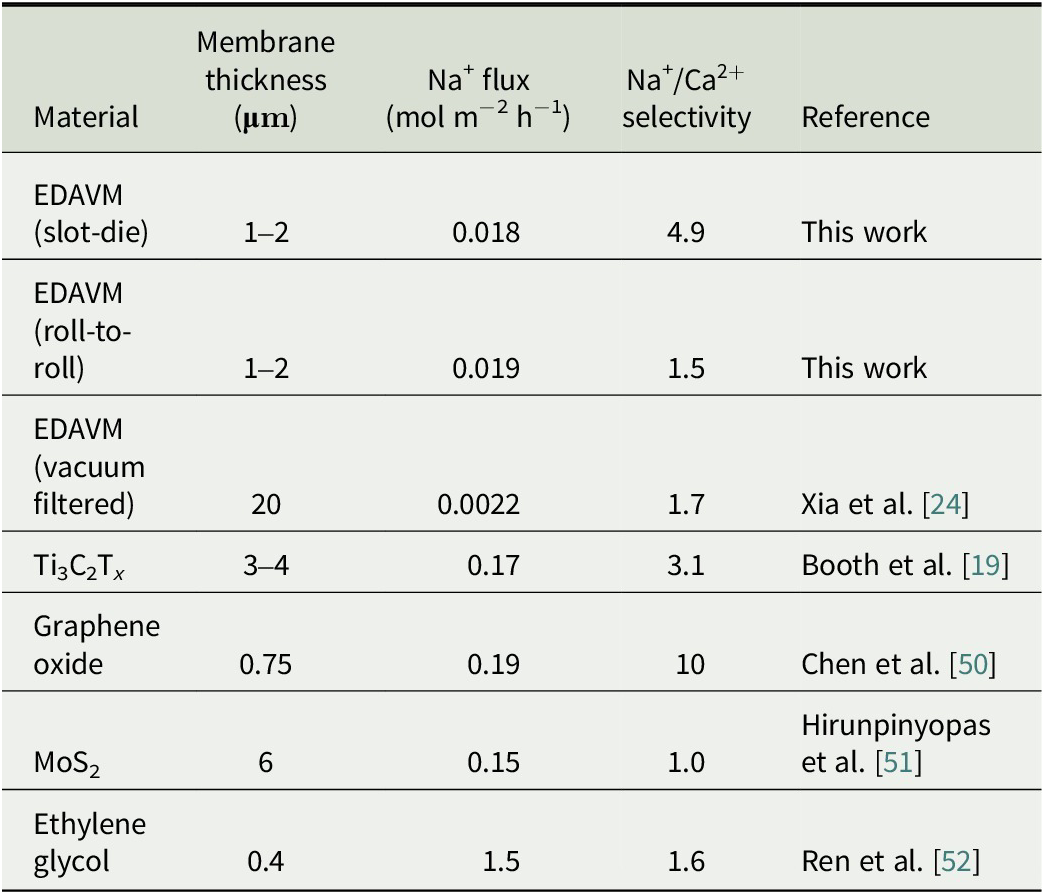
Table 2 presents a comparison of the scaled-up VM membranes from this work with previously reported small-batch EDAVM membranes and other types of nanofiltration membranes. In this table, salt permeability was converted to ion flux (mol m−2 h−1) for comparison with other 2D-material membrane studies that report this parameter, which is not normalized by membrane thickness. We also note that selectivity for most of the membranes reported here is based on the ratio of single-salt tests, rather than true multi-ion selectivity. Table 2 indicates that the scalably synthesized membranes from this work show similar Na+/Ca
$ {}^{2+} $
 selectivity compared with most other types of 2D-material–based membranes, indicating reasonable separation performance. The ion flux through EDAVM is notably lower than through other nanofiltration materials of similar thickness, which could make these membranes promising candidates for desalination or other applications requiring high rejection rates.
Comparison of baseline membrane properties (thickness, Na+ flux, and Na+/Ca
$ {}^{2+} $
 selectivity) between this work, previously reported MXene membranes, other 2D-material–based membranes, and conventional nanofiltration membranes.

Table 2. Long description
The table consists of five columns: Material, Membrane thickness in mu m, N a super plus flux in mol m super minus 2 h super minus 1, N a super plus / C a super 2 plus selectivity, and Reference.
* E D A V M (slot-die): thickness 1 to 2, flux 0.018, selectivity 4.9, Reference: This work.
* E D A V M (roll-to-roll): thickness 1 to 2, flux 0.019, selectivity 1.5, Reference: This work.
* E D A V M (vacuum filtered): thickness 20, flux 0.0022, selectivity 1.7, Reference: Xia et al.
* T i sub 3 C sub 2 T sub x: thickness 3 to 4, flux 0.17, selectivity 3.1, Reference: Booth et al.
* Graphene oxide: thickness 0.75, flux 0.19, selectivity 10, Reference: Chen et al.
* M o S sub 2: thickness 6, flux 0.15, selectivity 1.0, Reference: Hirunpinyopas et al.
* Ethylene glycol: thickness 0.4, flux 1.5, selectivity 1.6, Reference: Ren et al.
4. Conclusion
This work represents a proof of concept for scaling up the fabrication of phyllosilicate (VM) membranes beyond conventional benchtop methods such as vacuum filtration. Slot-die coating is a facile process for preparing large-area VM membranes 1–2
$ \unicode{x03BC} \mathrm{m} $
 in thickness. The methods developed for slot-die coating can also be easily transferred to a roll-to-roll apparatus, allowing for fabrication of VM membranes over 1 m in length. Batch slot-die– and roll-to-roll–coated membranes demonstrated similar structures and ion transport behavior to membranes produced via vacuum filtration, indicating successful scalability. These results are a promising first step for bringing cost-effective and environmentally compatible phyllosilicate membranes to the nanofiltration industry.
Future objectives will include high-throughput testing of these membranes’ performance in various multi-ion mixtures, as well as method development for scaling up other types of inorganic and 2D-material–based membranes. Future studies on 2D-material–based nanofiltration membranes with reduced thickness (i.e., 100–200 nm, rather than the commonly studied
$ >1 $
 $ \unicode{x03BC} \mathrm{m} $
 membranes) would also be valuable. This modification would improve the permeability of 2D-material membranes and bring them closer to the active layer thickness of commercially available nanofiltration membranes [Reference Boussu, De Baerdemaeker and Dauwe53, Reference Freger54]. A comprehensive exploration of coating conditions, including various coating rates and wet film thicknesses, would also be helpful for optimizing the synthesis protocol and achieving truly pilot-scale fabrication. Furthermore, pressure-driven tests should be conducted on phyllosilicate membranes in realistic systems such as dead-end or crossflow filtration, similar to our past work [Reference Liu, Wang and Sengupta23]. These testing schemes would confirm phyllosilicate membranes’ performance in configurations commonly found in industry, rather than the low-throughput model system of diffusion testing.
Open peer review
To view the open peer review materials for this article, please visit http://doi.org/10.1017/S2978171X26000019.
Supplementary material
To view supplementary material for this article, please visit http://doi.org/10.1017/S2978171X26000019.
Author Contributions
A.B. and M.A.K. designed and performed the experiments and analyzed the data. M.A.K. and S.D. conceived the original idea for the project and were in charge of overall direction and planning. K.S. performed profilometry measurements and analyzed profilometry data. K.H. and S.D. provided feedback and assisted in interpreting the results. A.B. wrote the manuscript with input from all authors.
Acknowledgements
This work was supported by the Advanced Materials for Energy-Water Systems (AMEWS) Center, an Energy Frontier Research Center funded by the US Department of Energy, Office of Science, Basic Energy Sciences. The submitted manuscript has been created by UChicago Argonne, LLC, Operator of Argonne National Laboratory (“Argonne”). Argonne, a US Department of Energy Office of Science laboratory, is operated under Contract No. DE-AC02-06CH11357. The US government retains for itself, and others acting on its behalf, a paid-up nonexclusive, irrevocable worldwide license in the said article to reproduce, prepare derivative works, distribute copies to the public, and perform publicly and display publicly, by or on behalf of the government. Work performed at the Center for Nanoscale Materials, a US Department of Energy Office of Science User Facility, was supported by US DOE, Office of Basic Energy Sciences, under Contract No. DE-AC02-06CH11357. This material is based upon work supported by the US Department of Energy, Office of Science, Office of Workforce Development for Teachers and Scientists, Office of Science Graduate Student Research (SCGSR) program. The SCGSR program is administered by the Oak Ridge Institute for Science and Education (ORISE) for DOE. ORISE is managed by ORAU under contract number DE-SC0014664. All opinions expressed in this paper are the authors’ and do not necessarily reflect the policies and views of DOE, ORAU, or ORISE. We thank Dr. Yuepeng Zhang and Mr. Samuel Miller (Materials Engineering Research Facility, Argonne National Laboratory) for their assistance with the roll-to-roll coating.
Competing Interests
Author Seth Darling is the Editor-in-Chief of Cambridge Materials: Water. Seth Darling was not involved in the editorial handling of this manuscript, or in the decision to publish. The peer review process was managed independently by the Associate Editor William Phillip.
Data Availability Statement
The data that support the findings of this study are available from the corresponding author, S.D., upon reasonable request.


 Open access


Comments
Dear Editors of Cambridge Materials: Water,
I am pleased to submit the manuscript entitled “Scalable Slot-Die Coating of Phyllosilicate Membranes for Selective Ion Separations” for consideration for publication in Cambridge Materials: Water.
This manuscript reports a scalable manufacturing approach for two-dimensional phyllosilicate (vermiculite) membranes using slot-die and roll-to-roll coating, addressing a critical bottleneck that has limited the translation of 2D-material-based membranes from laboratory studies to practical water treatment and resource recovery applications. By demonstrating meter-scale fabrication of thin (1-2 µm), mechanically robust membranes with ion-selective transport properties comparable to vacuum-filtered benchmarks, this work advances the technical maturity of clay-based membranes toward industrial relevance.
Phyllosilicates offer a compelling combination of low cost, environmental compatibility, and tunable nanoscale transport pathways. The results presented here show that these advantages can be retained under scalable processing conditions while enabling selective monovalent-multivalent ion separations relevant to water purification and critical materials recovery. We believe this contribution aligns strongly with the mission of Cambridge Materials: Water by bridging fundamental materials science with scalable manufacturing and water-focused applications.
The manuscript is original, has not been published previously, and is not under consideration for publication elsewhere. All authors have approved the submitted version of the manuscript and declare no conflicts of interest.
Thank you for your consideration of this work. We appreciate the opportunity to submit to Cambridge Materials: Water and look forward to your response.
Best regards,
Seth Darling