I. INDTRODUCTION
In contrast to conductive charging systems, inductive power transfer (IPT) systems do not require a physical connection between the battery and the charging station. Therefore, inductive charging stations are much more comfortable and user friendly, especially during poor weather conditions. They are safe against vandalism as all devices are encapsulated in the vehicle and the ground. This is why IPT systems cover a broad range of application: they are used for charging portable devices, biomedical implants, vehicles, and much more. They find application for various power ranges and various air gaps [Reference Boys and Covic1, Reference Nagendra, Covic and Boys2]. Stationary charging is further developed to dynamic charging where the vehicle is charged while it is actually moving [Reference Lukic and Pantic3, Reference Vilathgamuwa and Sampath4].
As IPT systems for charging electric vehicles (EVs) are increasing their market share, there also are various coupler topologies, which are deployed by the various car manufacturer, infrastructure companies, and wireless power transfer suppliers. In order to ensure a good interoperability between different coil topologies, there are several international and national standardization bodies, which focus on the specification of the components on the vehicle as well on the infrastructure side.
At present, standardization bodies contemplate a solenoid coil for the vehicle side, as it is a promising design. Compared with other topologies, a solenoid has a good coupling coefficient with small dimensions at the same time. To date, however, there is little published information on the specific design of a solenoid for IPT EVs. Therefore, this study identifies the main variables on the coil system and highlights their impact on the system behavior. The aim of this work is to get a profound knowledge of the design and optimization of a solenoidal coil.
In the first part of this section, current literature and the current state of knowledge are analyzed. Furthermore, several national and international standardization bodies dealing with IPT systems for EVs are presented. The third part shortly explains the fundamentals of an IPT system. In Section II, the influence of the main geometric variables of a solenoidal coil is analyzed using parameter studies. Based on these findings a coil system is designed and optimized for a specific case of application in Section III. In Section IV, simulation results are validated and verified. Finally, Section V summarizes the findings and further areas of research are identified.
A) State of knowledge
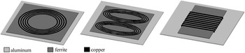
Currently primarily three types of coupler topologies are applied in IPT applications for charging EVs: circular planar, bipolar, and solenoidal coils, as illustrated in Figure 1 [Reference Li and Mi5].
They differ from each other mainly in the nature of their generated flux: a circular coil, as a nonpolarized coupler, generates a perpendicular flux, whereas DD coils or solenoids are polarized couplers, as they generate a parallel flux. Bipolar pads, which have mutually decoupled partially overlapping coils, can couple power from both the parallel flux and the perpendicular flux [Reference Zaheer, Hao, Covic and Kacprzak6]. As bipolar pads are able to effectively couple with various coil topologies, they are particularly suitable for an interoperable power transfer. Since the bipolar pad is known to interoperate with the other coil designs, the bipolar design is chosen in this study as a universal primary topology [Reference Boys and Covic1, Reference Lin, Zaheer, Budhia and Covic7]. Besides, the standard IEC 61980-3 also recommends the bipolar coil architecture as a primary topology [8].
On the secondary side, a solenoidal coil is chosen in this paper, as this architecture has a promising performance. It has a generally better coupling and smaller dimensions than other coupler topologies. However, the magnetic stray fields are relatively high [Reference Ombach, Kürschner, Mathar and Chlebosz9]. The standard IEC 61980-3 also recommends, among others, a secondary solenoidal coil [8].
Coupler topologies for IPT.

In order to exploit the full potential of the solenoid coil, an accurate magnetic design is indispensable. Nevertheless, to date there is little published information on the specific design of a solenoid for IPT of EVs.
Most studies focused on partial aspects of the coil design, as in [Reference Tang, Zhu, Wang and Ma10–Reference Huang12], where specific cases of applications are assumed. Thus, the findings of these studies can be used for the design of other solenoids only to a limited extent. Hence, in this paper a comprehensive parameter study is conducted. All geometric variables are varied likewise and their influence on the entire output variables is examined. The aim of this work is to get a profound knowledge of the design and optimization of a solenoidal coil.
B) Standardization activities
In this section, the current standardization activities for IPT systems are presented. There are several international and national standardization bodies, such as ISO (PAS 19363), SAE (J2954), IEC (61980), and ICNIRP. ISO, SAE, and IEC categorize IPT systems according to several air gap classes and power transfer classes. In addition, they develop specifications for the components on the vehicle-side as well as on the infrastructure side.
Guidelines on the exposure to time-varying electric, magnetic, and electromagnetic fields are issued by the International Commission on Non-Ionizing Radiation Protection (ICNIRP). In order to protect against any known health effect, the exposure limit for the magnetic stray field of 27 µT for a frequency range of 3–10 MHz has to be met [13]. Previous ICNIRP guidelines from 1998 restrict the magnetic stray field to 6.25 µT [14]. The main standardization bodies and their standards are summarized in Table 1.
Standardization activities.

C) Fundamentals of IPT systems
Figure 2 shows the main components of an IPT system. The primary system is fed by a primary AC source. Power electronics convert the low-frequency grid current into a high-frequency output current to feed the primary coil [Reference Fisher, Farley, Gao, Bai and Tse15]. In loosely-coupled coils, such as the ones used in IPT, leakage inductances are large. Therefore, reactive power needs to be compensated in order to prevent further losses. This is done by compensating capacitors, which form resonant circuits with the coils [Reference Trevisan and Costanzo16]. The secondary part of the IPT system is composed similarly. In automotive applications, the secondary power converter usually consists of a rectifier and a chopper to feed the vehicle's battery.
Inductive power transfer system.

The output power of the system can be determined using the open-circuit voltage V oc and the short-circuit current I sc [Reference Boys and Covic17]:
 $$P_{out} = I_{sc} \cdot V_{oc} \cdot Q_2. $$
The open-circuit voltageand the short-circuit current are calculated as follows:
 $$V_{oc} = \omega \cdot M \cdot I_1, $$
 $$I_{sc} = \displaystyle{M \over {L_2}} \cdot I_1. $$
This leads to the following expression for the output power P out :
 $$P_{out} = \omega \cdot I_1^2 \cdot M^2 \cdot \displaystyle{{Q_2} \over {L_2}}. $$
With the magnetic coupling coefficient k,
 $$k = \displaystyle{M \over {\sqrt {L_1 \cdot L_2}}}, $$
the output power can also be written as:
 $$Pout = \omega \cdot L_1 \cdot I_1^2 \cdot Q_2 \cdot k^2. $$
As expression (6) shows, the output power can be increased by using a higher frequency, a larger primary current, or a higher quality factor Q 2. Increasing the frequency is limited due to switching losses in power electronic devices. Using a larger primary current also results in larger copper losses. The quality factor of the coils is limited by manufacturing technology and costs. Therefore, the magnetic design has to be improved in order to increase the transferred power [Reference Boys and Covic17].
II. PARAMETER STUDY
A) System definition
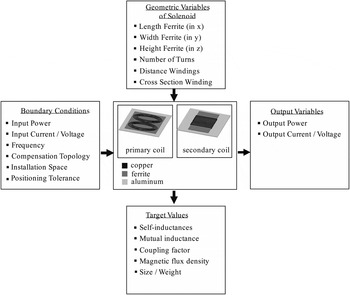
Before defining the specific variables and their limits for the parameter study, the overall system with its input and output quantities is defined first, as illustrated in Fig. 3. Central elements of the parameter study are the primary and the secondary coil with aluminum and ferrite plates. On the primary side a universal bipolar topology is used, which is kept constant for all simulations. The solenoid coil with a box-shaped ferrite core on the secondary side is examined in detail in this study. Other components, such as power electronic devices, are not part of the examination.
System definition.

Input quantities of the system are the primary power input P 1, the primary current I 1, and the transfer frequency f. Output quantities are the secondary induced voltage U 2 as well as the secondary current I 2. The input power is chosen to be 22 kW and the input current amounts to 85 A peak value. A fully compensated system is assumed. In order to be able to compare the various parameter settings, a constant transferred power is assumed. Thus, the secondary current is imposed accordingly.
Target values in this study are at one hand the self-inductances, the mutual inductance, and the coupling coefficient k. On the other hand, the magnetic field at the vehicle body has to meet the requirements of the ICNIRP guidelines. In order to take several vehicle types and their various widths into account, the magnetic flux density is evaluated at different distances and positions around the coils. Furthermore, size and weight of the coil system are a target value.
In order to analyze the positioning tolerance of the coil system, lateral displacements of 0–70 mm in the x-direction and 0–100 mm in the y-direction were taken into account.
All values are based on to the current state of technology and on the current requirements of the standardization bodies, see also Table 1.
B) Parameter study
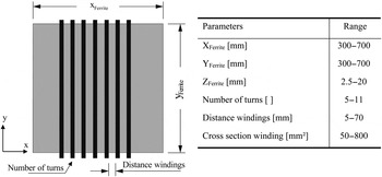
As illustrated in Fig. 3, a bipolar pad is used as primary coil. The secondary coil, focus of this parameter study, is a solenoid with a box-shaped ferrite core. The range of the parameters varied also is listed in Fig. 4.
Geometric parameters of the solenoid and their range.

Each of the parameters of the secondary coil is simulated as a linear parametric sweep in ANSYS Maxwell, while the other parameters remain fixed. For each variation, the self- and mutual inductances as well as the magnetic coupling coefficient and the flux density values are calculated. The magnetic flux density is evaluated at three distances from the coil center: at 850, 1050, and 1250 mm. The smallest distance of 850 mm, as a worst case scenario, represents the vehicle body of a small car (e.g. a smart with a vehicle width of 1663 mm [18]). In order to take also larger vehicles into account, the magnetic flux density is calculated as well at distances of 1050 and 1250 mm.
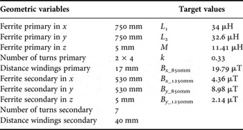
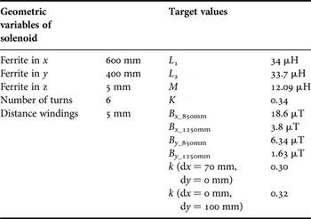
The dimensions of the reference system and its target values are listed in Table 2.
Dimensions and characteristics of the reference model.

C) Results of parameter study
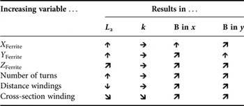
In view of the extent of the results of the parameter study, only the most important results are discussed below. Table 3 gives a quantitative overview of the influence of the factors on the target values.
Effects of the factors on the target values.


 , considerable effect;

 , moderate effect;
 , marginal effect.
As the ferrite length in the x-direction increases, the flux pipe, dependent on the size of the ferrite, also gets larger. As it provides a path with less magnetic resistance, the self-inductance, as well as the flux density around the coil rises. The increase of the magnetic field in the x-direction is substantially larger than in the y-direction. Enlarging the ferrite in the y-dimension shows similar behavior, with an enlarged increase of the magnetic flux density in the y-direction. Overall effects of an enlargement of the ferrite height are generally not as strong as the effects of an enlargement in the x- or y-directions. Nevertheless, a moderate increase of the self-inductance as well as the flux density in both directions can be observed.
A large distance between the turns has a negative impact on the magnetic flux, as more flux passes between the windings. For this reason, the magnetic field in the surrounding of the coils increases. Moreover, the self-inductance decreases considerably.
The cross-sectional area of the litz wire also is under examination. Enlarging the cross-section results in a slight increase of the flux density. The self-inductance is reduced.
In the following optimization, however, the cross-sectional area is kept fixed as it is predominantly determined by the demanded ampacity.
Varying the factors, the coupling coefficient k shows a non-monotonic behavior, with different local maxima, depending on the factor's size. Only the factor of the conductor cross-section has a monotonic impact on the coupling factor.
Furthermore, the influence of a lateral misalignment on the IPT system is studied. As depicted in Fig. 5, it can be seen that a misalignment affects as well the coupling as the magnetic flux density on the vehicle body. In general, the system is much more sensitive to a misalignment in the x-direction than in the y-direction.
Influence of a lateral misalignment.

III. OPTIMIZATION
A) Approach
Based on the previous findings, the solenoid can now be optimized. The coupling factor shows local optima for various parameter settings. As there are strong interactions between the geometric variables, the main effects of the parameter study cannot be sensibly interpreted. In order to take the interaction effects between the factors into account, complex optimization algorithms are needed. However, because of the large number of variables the computational effort would be immensely high. Thus, a first iterative optimization, based on the main findings of the parameter study is conducted. In a second step, further room for improvement then is identified.
The main findings for the subsequent optimization are as follows:
-
- In order to reduce the magnetic flux density at the vehicle body the dimensions of the solenoid have to be decreased. Hereby, particular attention should be paid to the magnetic flux density in the y-direction, transversal to the driving direction. In the driving direction, the magnetic flux density at the vehicle body is well below the requirements of the ICNIRP guidelines.
-
- In order to adjust the inductances of the coils the number of windings and the distance between the windings can be varied. It is suggested first to regulate the number of windings for a coarse adjustment, as it only can be varied in discrete steps. A fine adjustment can be done by varying the distance of the windings.
-
- The distance of the windings shall be increased to a limited extent, as an enlarged distance affects the coupling factor and the magnetic stray field adversely.
These main findings lead to an iterative optimization approach.
B) Optimization results
According to the previously described optimization approach, the optimized solenoid shows the following dimensions and target values, as listed in Table 4.
Optimization results.

The length of the solenoid in the x-direction was increased from 530 to 600 mm, whereas the width in the y-direction decreased from 600 to 400 mm. The distance of the windings reduces from 40 to 5 mm. In order to attain a similar self-inductance compared with the reference system, the number of windings was slightly reduced from seven to six windings. Due to this optimization, the magnetic flux density could be significantly reduced: in the x-direction a decrease of 13% and in the y-direction a decrease of 30% could be noticed. Regarding the coupling factor the optimization results in an increased coupling factor under misalignment: in condition of an offset of 70 mm in the x-direction, the coupling factor can be increased from 0.28 to 0.30, in condition of a lateral misalignment of 100 mm, the coupling increases from 0.31 to 0.32. The coupling factor in nominal position only changes marginally to 0.34.
C) Weight minimization
The results of the previous optimization have shown that it is possible to reduce volume, weight, and flux density substantially without suffering from reductions of the coupling factor. These findings raise the question to which extent a further reduction of size influences the coupling factor. For this reason, additional simulations were conducted.
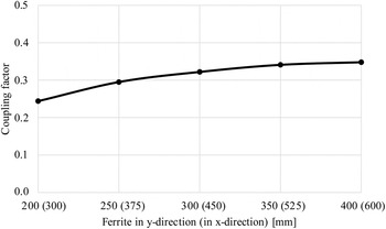
With a constant width-to-length ratio of 1:1.5, the size of the ferrite was gradually decreased, while keeping the other parameters fixed. As Fig. 6 shows, the size of the solenoid can further be minimized to 300 mm × 450 mm without any substantial change of the coupling coefficient. Furthermore, the reduced size of the solenoid results in a decrease of the magnetic flux density. The magnetic field at the vehicle body was reduced by up to 36% in the x-direction and up to 46% in the y-direction. Volume and weight of the ferrite were reduced by more than 50%.
Coupling factor when minimizing weight.

IV. VALIDATION AND VERIFICATION
As all results of this study are based on numerical simulations, they are only approximate simulations. In this section, the possible errors made are quantified. For the numerical simulation, there are two main steps: At first modeling the system and afterwards solving the differential equations. A validation ensures for the first step that the correct model is built and that the model is an accurate representation of the real model. For the second step, a verification estimates the deviation between the exact mathematical solution and the numerical approximated solution.
A) Verification
In order to quantify the quality of the numerical solution, several convergence criteria were defined. The mesh is refined adaptively until the specific convergence criteria are fulfilled. More precisely, a percentage energy error of 1% was defined as convergence criterion. Furthermore, the change of the inductances from one pass to another has to be smaller than 0.5%. In order to evaluate the quality of the numerical mesh in the surroundings of the coil system, the quality of the magnetic field was taken into account as well. For simulations with an axis of symmetry, the deviation of the magnetic field between the symmetrical planes was calculated. All simulations conducted in this study fulfill the defined convergence criteria to its full extent.
B) Validation
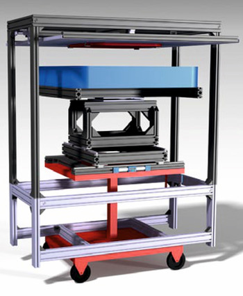
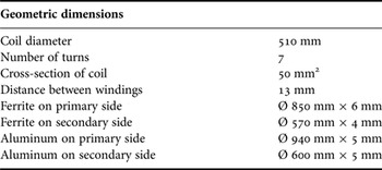
For the estimation of the model error, simulation results were compared with the results of an experimental prototype, as shown in Fig. 7.
3D CAD model of the experimental prototype [Reference Baier and Ehrentraut19, Reference Mayer20].

Due to reasons of complexity a prototype with circular planar coils was built, which fulfills the previously boundary conditions and requirements to its full extent. The dimensions of the experimental prototype are summarized in Table 5.
Dimensions of the experimental prototype.

The existing simulation models were adapted accordingly and compared with the results of the experiments. For the measurements of inductances, 15 points were defined, which follow various lateral misalignments in the x- and y-directions (0, 25, 50, 75, and 100 mm) and various operational air gaps (120, 135, and 150 mm). The magnetic flux density also was measured and compared with the simulation results. As shown in Table 6, the averaged deviation between the measured and simulated results is well below 10%. The averaged absolute deviation of all measuring points is below 5%. It can be seen furthermore that the absolute deviation of all measuring points as well as the maximum deviation also are subject to a small error.
Validation results.

V. CONCLUSION
In this work, the influence of the main geometric variables of a solenoid was analyzed in detail. With a comprehensive parameter study, all geometric variables were varied likewise and their influence on the target values was examined. The most important geometric variables were identified and their specific influence on the behavior of the system was explained. Based on these findings, the coil system was then optimized. In a first approach, the coil size could be reduced by 17% with a constant coupling factor at the same time. In addition, the magnetic flux density at the vehicle body was reduced by 30%. A further optimization revealed that a further reduction in coil size is possible by more than 50% with an approximate constant coupling factor. The magnetic stray field at the vehicle body was reduced in this case by 46%. All simulations conducted in this study are validated and verified.
Further studies can be carried out to analyze and optimize the shielding of the coil system in order to meet the requirements of an adequate positioning tolerance. As a next step, an adapted experimental prototype is built and measured. Moreover, it is to show, to what extent these findings are applicable to other topologies. A comparison of several secondary topologies with a bipolar magnetic coil design on the primary side can highlight the specific advantages and disadvantages of each topology.
 Katharina Knaisch received her Mechanical Engineering diploma in 2013 from the Karlsruhe Institute of Technology (KIT). She now is a Ph.D. student at the Institute of Vehicle System Technology at the KIT. Her research areas include the design and optimization of coil topologies for inductive power transfer for electric vehicles with high power.
 Tom Huck studied mechatronics at the Karlsruhe Institute of Technology (KIT). In his bachelor thesis, he analyzed coil designs for inductive power transfer. After his current internship at the Department of e-mobility at Schaeffler Group, he will aim for the master's degree in Electrical Engineering.
 Peter Gratzfeld is a full Professor at the Institute of Vehicle System Technology at the Karlsruhe Institute of Technology (KIT). He received his Ph.D. degree in Electrical Engineering from the RWTH Aachen University. From 1986 to 2008, he held several leading positions within the rail industry at Bombardier Transportation and its predecessor companies.