Nomenclature
- A
Area
- Cp
Heat capacity at constant pressure
- H
Heat load
- k
Slope of fitting straight-line
- K
Kelvins(international unit of thermodynamic temperature)
- m
Mass flow rate; meter
- M
Mach number
- p
Pitch
- P
Total pressure
- PHV
Pressure arm of leading edge horseshoe vortex formed on the tip surface near the leading edge
- q
Heat flux
- R
Linear correlation coefficient
- SHV
Suction arm of leading edge horseshoe vortex formed on the tip surface near the leading edge
- t
Static temperature
- T
Total temperature
- V
Velocity
- VEGR
Viscous entropy generation rate
- w
Winglet width
- W
Watt(international unit of power)
- ZISTR
Zero inlet swirl turbine rotor
Greeks
- α
Angle between injected flow and mainstream
- θ
Angle of trace of suction arm of leading edge horseshoe vortex
- η
Efficiency
- ω
Vorticity
- γ
Specific heat ratio
- π
Relative total pressure loss coefficient
- ζ
Flow loss
- μ
Viscosity
Subscripts
- 1
Rotor inlet
- 2
Rotor exit
- EM
External mixing loss
- L
Leakage flow loss
- injected
Injected flow
- IG
Internal gap loss
- Improved
Improved rotor with tip winglet
- main
Mainstream
- nt
Blade without no tip clearance gap
- N
Case number
- Original
Original rotor without tip winglet
- rel
Relative flow parameters in the local reference frame of the rotor blade
- s
Streamwise
- wt
Blade with tip clearance gap
1.0 Introduction
A zero inlet swirlturbine rotor (ZISTR) directly operates downstream of a combustion chamber as the first turbine stage in a multistage vaneless counter-rotating turbine which only consists of four rotors without any vanes [Reference Zhao, Wu and Xu1, Reference Zhao, Zhao and Sui2]. The vanes upstream of a ZISTR are removed to reduce the weight and length of a multistage vaneless counter-rotating turbine, which leads to stagger angles more than 73 degrees and blade deflections less than 0.5 degree for the ZISTR blade profiles. Due to small flow turning in its passage, there is no obvious passage vortex. Without obstruction of the passage vortex, the tip leakage vortex develops in a large size, taking up more than 1/3 blade span at the rotor exit, generating a large amount of flow losses. Investigations on methods of tip leakage flow loss reduction are indeednecessary.
For unshrouded turbine rotors, different design methods of blade tip are commonly employed to reduce the tip leakage flow loss, such as squealers [Reference Booth, Dodge and Hepworth3–Reference Zou, Shao and Li11], winglets [Reference Yaras and Sjolander12–Reference Zhou and Zhong23] and combinations of squealers with winglets [Reference Saha, Acharya, Bunker and Prakash24–Reference Schabowski, Hodson, Giacche, Power and Stokes26]. Squealers are rims protruding from the tip surface in the spanwise direction. Winglets are small plates extending from the tip of the blade that act to reduce the leakage flow into (pressure side) or out of (suction side) the tip gap region.
For the study of squealers, Camci et al. [Reference Camci, Dey and Kavurmacioglu5] experimentally studied the flow physics of partial squealer rims with different lengths and heights of a single stage cold turbine. It was found that the suction side partial squealers could significantly reduce the stage exit total pressure defect associated with the tip leakage flow. The squealer rims, which extended from the trailing edge to about 6% axial chord location, achieved the best performance among suction side squealers with different chordwise lengths. Lee et al. [Reference Lee and Chae8] studied the effects of squealer rim height on aerodynamic characteristics and flow losses of a high-turning turbine rotor. It was found that, as the squealer rim height increased, the tip leakage vortex was weakened and hence its interaction with the passage vortex was weakened. Once the squealer rim height-to-chord ratio exceeded 5.51%, it could not offer an effective reduction in aerodynamic loss. Li et al. [Reference Li, Jiang, Zhang and Lee10] numerically studied the over-tip-leakage flow of a typical squealer tip design in a high pressure turbine blade in transonic condition. It was found that, under transonic condition, the flow ejecting from the squealer cavity induced a relatively large flow separation zone with lower momentum, which reduced the effective choking throat area. As a result, even in the choking condition, the overall over-tip-leakage flow flux was still reduced. In summary, the location and height of the squealers both are important factors in reducing the tip leakage flow loss, so they should be chosen carefully.
For the study ofwinglets, Lee et al. [Reference Lee, Kim and Kim16] investigated effects of a pressure-side winglet and a leading-edge and pressure-side winglet on the aerodynamic performance in a turbine cascade. It was found that, affected by both kinds of winglets, the aerodynamic loss in the tip leakage vortex region as well as in an area downstream of the winglet-pressure surface corner was reduced, but that in the central area of the passage vortex region increased. Zhou et al. [Reference Zhou, Hodson and Tibbott18] conducted an experimental and numerical investigation on the aerodynamic performance of a winglet tip in a linear cascade. It was found that, the suction side winglet reduced the driving pressure difference of the tip leakage flow near the leading edge, but increased the driving pressure difference from mid-chord to the trailing edge. This was because the static pressure at the exit of the tip gap was affected by the leakage vortex with low static pressure. As a result, compared to a flat tip, the reduction of the tip leakage mass flow resulted from the winglet tip was small. Lee et al. [Reference Lee, Cheon and Zhang20] studied the effect of full coverage winglets with different winglet widths on tip leakage aerodynamics of a turbine cascade. It was found that, as the winglet width increased, the passage vortex was weakened and the tip leakage vortex became stronger and wall-jet-like. Up to winglet width-to-pitch ratio = 10.55%, the aerodynamic loss all over the measurement plane decreased steeply and then it became almost unchanged. Zhou et al. [Reference Zhou and Zhong23] proposed a novel suction side winglet design method. It was found that, on the casing end-wall, the winglet increased the pressure and reduced the tip leakage flow. The mechanical performance of the blade with winglet was also validated. The Von Mises stress was high at the interface between the winglet and the blade. To mitigate the high stress, the connection between the winglet and blade surface had been changed into a smooth curve rather than a sharp corner, and the maximum stress was reduced from 350Mpa to 150Mpa, which was acceptable for the engine application. In summary, the winglet could decrease the driving pressure difference on the tip and reduce the tip leakage flow, and it also could reduce the strength of passage vortex, thereby improving the turbine performance.
For the study of combinations of squealers with winglets, Saha et al. [Reference Saha, Acharya, Bunker and Prakash24] numerically investigated effect of a pressure-side winglet on the flow and heat transfer over a blade tip. A flat tip case and a squealer tip case are performed and compared. For the flat tip, affected by the winglet, the reduction in the tip leakage vorticity was nearly 25% at 70% span and 60% axial chord, and the average heat transfer coefficient was reduced by about 7%. However, in the presence of a squealer, the role of the winglet decreased and only 1.5% decrease in the average heat transfer coefficient was obtained. Schabowskiet al. [Reference Schabowski, Hodson, Giacche, Power and Stokes26] used a numerical method to optimise a winglet-squealer geometry and verified the optimisation results through low-speed cascade testing. It was found that, for all of the tested tip gaps, the optimised winglet-squealer design had a lower loss than the flat tip. This optimised design offered a 37% reduction in the rate of change of the aerodynamic loss with the tip gap size.
Above studies showed that squealers, winglets and the combination of squealers with winglets were able to reduce the tip leakage flow loss for the traditional unshrouded turbine rotors. It should be note that, the squealers have been applied in the current gas turbines, but there are few published literatures of the application of winglets in the current gas turbines. The application of winglets in gas turbines may face some problems [Reference Tallman27]. For example, the cooling design of winglet is difficult in high-temperature turbines, and the winglet may simply burn off. The winglet may break off and potentially damage downstream blade rows. Thus, most investigations on winglets have been conducted by numerical methods and experiments, and the application of winglet still needs to be further explored.
For the ZISTR, none of above methods for leakage flow loss reduction have been investigated by now. In this paper, the method of flat-tipped winglet without any squealers is chosen to reduce tip leakage flow loss for the ZISTR. It should be noted that further investigations on the squealers or the combinations of squealers with winglets for the ZISTR are still necessary.
In general, a blade tip winglet designed on the suction side achieves much more benefits than that designed on the pressure side. Yaras and Sjolander et al. [Reference Yaras and Sjolander12] investigated three different winglet geometries. They found that a much larger driving pressure reduction is caused by using the suction side winglet when compared with the pressure side one. This is because, in the blade-to-blade plane, the static pressure gradients normal to the blade surface are much higher close to the blade suction side than the pressure side. Coull et al. [Reference Coull, Atkins and Hodson19] conducted a survey of different winglets designed on the flat-tip, with a view to maximising aerodynamic efficiency while minimising heat transfer. They found that the designs with only pressure surface tend to give modest efficiency gains or relatively high heat load, and the designs with a suction surface overhang over the full width of the blade lie close to the best-trade-off line, and so tend to give large efficiency improvements for modest increases in heat load. Cheon and Lee [Reference Seo and Lee22] experimentally investigated winglet geometry effects on loss for the plane tip. They found that the suction-side winglet leads to a significant loss reduction, probably because the tip leakage flow is separated from the casing all the way from the leading edge up to the mid-chord, which decreases overall tip leakage outflow rate. On the contract, the pressure-side winglet leads to a remarkable loss increase, probably because the pressure-side winglet brings additional flow disturbances similar to the ones existing over the plane tip back to the tip gap flow over the squealer tip. Based on these findings, it is reasonable to design a tip winglet on the suction side to reduce the tip leakage flow loss for theZISTR.
When using a suction side winglet, the loss reduction usually benefits from the decrease of the intensity of the passage vortex. Cheon and Lee [Reference Seo and Lee17] found that suction-side winglets have a role to increase aerodynamic loss in the tip leakage vortex region but reduce aerodynamic loss in the passage vortex region, contributing to a net reduction in aerodynamic loss. Coull et al. [Reference Coull, Atkins and Hodson19] found that suction side winglets reduce the interaction between the tip leakage flow and the passage vortex early in the blade passage, significantly reducing the magnitude of the passage vortex loss core and improving the efficiency. Zhou et al. [Reference Zhou and Zhong23] found that the winglet tip increased the turbine stage efficiency by 0.9% mainly by eliminating the loss caused by the passage vortex at a tip gap size of 1.4% chord compared to acavity tip.
However, different from traditional transonic turbine rotors, in the ZISTR, there is no obvious passage vortex due to its blade deflections less than 0.5 degree. Hence, for the ZISTR using the suction side winglet, the mechanism and effectiveness of the loss reduction are still not clear. This paper presents a front suction side winglet design method for the ZISTR and investigates the effect of winglet width to explore its design space.
2.0 Geometry of zistr
The zero inlet swirl turbine rotor (ZISTR) is the first stage of the multistage vaneless counter-rotating turbine [Reference Zhao, Wu and Xu1, Reference Zhao, Zhao and Sui2], as shown in Fig. 1 [Reference Zhao, Wu and Xu1].
Schematic sketch of multistage counter-rotating turbine (1). 1-R1, 2-R2, 3-rotating frame, 4-R3, 5-R4, 6-vaned diffuse, 7-power shaft, 8-compressor driven shaft.

The vanes upstream of the ZISTR are removed, so its inlet flow from the combustion chamber is in an axial direction without any swirl, namely, zero inlet swirl. In the multistage counter-rotating turbine, the direction of rotation of R1 (ZISTR) and R3 is opposite to that of R2 and R4. The R1 (ZISTR) and R3 are directly connected to the compressor by a shaft. The work that the compressor consumes is the sum of the power output of R1 and R3. The R2 and R4 are used to drive a propeller. The work that the propeller consumes is the sum of the power output of R2 and R4.
The throughflow parameters of the ZISTR are listed in Table 1. The stagger angles are more than 73 degrees, and the blade deflections are less than 0.5 degree. The three-dimensional geometry of the original ZISTR is shown in Fig. 2. The blade cambers are almost straight and the airfoils are very thin. To explain these special features of the ZISTR, the velocity triangle of blade tip is shown in Fig. 3. The absolute, relative and rotational velocity vectors are labeled with the red, green and blue arrows respectively. The axial direction is from the top to the bottom.
Throughflow parameters for the ZISTR

Three-dimensional geometry of original ZISTR.

Velocity triangle of blade tip.

From the velocity diagrams depicted in Fig. 3, the lack of upstream vanes of the ZISTR leads to stagger angle of 75.02 degrees and blade deflection of 0.3 degree for the ZISTR tip profile. Due to the lack of upstream vanes, the inlet absolute velocity is in an axial direction, and its magnitude is much smaller than that of the rotational velocity. This difference constructs a high relative inlet flow angle of 75 degrees. The high relative inlet flow angle leads to a high stagger angle of 75.3 degrees for the ZISTR blade profile, since the stagger angle is usually higher than the inlet flow angle. This high relative inlet flow angle also limits the flow turning in the blade passage, because there is only a small margin for the increase in the relative exit flow angle. Thus, for all blade sections, the stagger angles are more than 73 degrees and the blade deflections are less than 0.5 degree, which result in almost straight cambers and very thin airfoils.
3.0 Numerical method
The ANSYS 14.0 CFX is used to solve the Reynolds-averaged Navier-Stokes (RANS) equations. Concerning the turbulence modeling, the Ref. [Reference Coull, Atkins and Hodson19] has proved that the two-equation shear stress trans- port (SST) turbulence model is capable to capture the flow physics inside the blade tip gap of the transonic turbine, so this turbulence model is selected for the present study. When a convergence is reached, the residuals of continuity equation, momentum equations and energy equation are less than 1e-5.
The boundary conditions are set to simulate the design condition, as illustrated in Fig. 4. A total pressure of 1160Kpa and a total temperature of 1250K are defined at the inlet of computation domain, which is located in 100% axial chord upstream of the leading edge. An average static pressure of 340Kpa is defined at the outlet of computation domain, which is located in 250% axial chords downstream of the trailing edge. The outlet of numerical domain which is used to calculate the flow loss and turbine efficiency, is chosen at 200% axial chords downstream of the trailing edge to avoid the impact of outlet condition. The tip clearance height is set as 1.5% blade height. Periodic boundary conditions are applied to circumference of a single blade to simulate a row of blades. Coolant flows have not been modeled in this study. To obtain the heat transfer of a blade, a constant wall temperature of a blade is specified as 760K, giving a gas to wall ratio of approximately 1.5, which is considered broadly representative of real engine conditions [Reference Coull, Atkins and Hodson19].
Illustration of boundary conditions.

The structured grids are used for all cases, which are generated with the topology of Autogrid-O4H by NUMECA software. The grid sensitivity is analysed by increasing the cell number from 1 million to 4 million, from Case number(N) = 1 to Case number(N) = 7, respectively. The turbine efficiency is defined as Equation (1), and the relative difference in efficiency is defined as Equation (2). The grid sensitivity results are listed in Table 2. It is found that, from 3 million cells, the relative difference in efficiency is less than 0.05%, so the gird with 3.5 million cells is used. Inside the blade tip gap, there are 35 layers of mesh in spanwise direction. The maximum of y plus is less than 1.2.
 \begin{align}\eta = {{1 - {{{T_2}} \over {{T_1}}}} \over {\left[1 - {{\left({{{P_2}} \over {{P_1}}}\right)}^{{{\gamma - 1} \over \gamma }}}\right]}}\end{align}
 \begin{align}\Delta {\eta ^*} = {{{\eta _{N + 1}} - {\eta _N}} \over {{\eta _N}}}\end{align}
Grid sensitivity results

4.0 Flow field of original zistr
Inthis section, the flow filed of an original ZISTR without the blade tip winglet will be analysed.
The Mach number distributions at 50% and 90% span are shown in Fig. 5. The ZISTR is a transonic blade whose relative outlet Mach number is about 1.5 as in Table 1, and at 50% span, there are two trailing edge shocks, a suction side trailing edge shock and a pressure side trailing edge shock. At 90% span, the leakage flow can be identified from a low-velocity region starting from the suction side leading edge, and the structure of suction side trailing edge shock is changed where the leakage flow reaches the trailing edge.
Mach number distributions at 50% and 90% span.

To trace the evolution of the tip leakage vortex core, black streamlines are released from the leading edge at blade tip, and downstream the trailing edge, the contour of relative total pressure loss coefficient, as defined in Equation (3), as shown Fig. 6.
Tip leakage vortex of original ZISTR.

From the black streamlines in Fig. 6, tip leakage vortex can be identified, and it develops away from the suction side. This is probably attributed to the small blade deflection of less than 0.5 degree of the ZISTR profiles. For this reason, the flow in the mainstream gets small centripetal force from the pressure field. In the mainstream pressure field, the force component in the direction to the blade wall is very small. As a result, when the tip leakage flow is injected into the mainstream, the tip leakage vortex develops downstream along a nearly straight track without obvious turning.
 \begin{align}\pi = {{{P_{1 - rel}} - {P_{rel}}} \over {{P_{1 - rel}}}}\end{align}
From the contour of relative total pressure loss coefficient in Fig. 6, the tip leakage vortex can be identified, and there are no other secondary vortical structures observed. This is because the flow deflection is less than 0.5 degree. Thus, for the ZISTR, there is no interaction between the tip leakage vortex and the passage vortex. This also indicates that the evolution of the tip leakage vortex lacks the obstruction from the passage vortex.
Without the obstruction of the passage vortex, the tip leakage vortex generates a large amount of losses, as seen from the contour of relative total pressure loss coefficient in Fig. 6. The region affected by the tip leakage vortex takes up more than 1/3 spanwise space. According to the numerical simulation results at the design condition, compared with the ZISTR without blade tip clearance, the efficiency of the ZISTR with a tip clearance height of 1.5% blade span dramatically degrades by 5%, from 88.30% to 83.31%.
5.0 Front suction side winglet
To reduce the tip leakage flow loss, a front suction side winglet is taken into consideration. This is because the leakage vortex initially generates from the leading edge, and an obstruction to the onset of leakage vortex through front suction side winglet is expected to an effective way for the mixing loss mitigation [Reference Zhou, Hodson and Tibbott18, Reference Coull, Atkins and Hodson19, Reference Seo and Lee22].
The front suction side winglet on the blade tip is illustrated in Fig. 7(a). The winglet is obtained by modifying the blade tip stream surface profiles (at 100% blade span) described by spline curves. There are five intermediate construction points fixed on the camber curve. From these intermediate control points, a specified width is added perpendicularly to the camber curve, and then the position of the spline control point of the profile is defined. To limit the winglet in the front part of suction side, only the control points of C1 and C2 are shifted, while at the same time, all construction points on camber curve are fixed. The front suction side winglet on the blade tip is obtained as follows:
-
1. The perpendicular width of C1 is increased to form the front suction side winglet.
-
2. Oncethe perpendicular width of C1 is decided, the perpendicular width of C2 is specified as the arithmetic mean of perpendicular width of C1 and C3. It should be noted that the perpendicular width of C3 is not changed, so that of C1 determines the profile of winglet.
-
3. The three-dimensional geometry of the rotor is created by radial stacking of two-dimensional stream surface profiles through their centers of gravity. The stacking line is straight since there the blade bow or sweep is not employed. These two-dimensional stream surface profiles are constructed by spline curves, located at 0%, 30%, 50%, 70%, 90%, 94% and 100% blade span. Except for the blade tip profile, the rest of stream surface profiles are remained unchanged. This means that, along the blade span, the shape of winglet extends from the tip-end to the 94% blade span.
Front suction side winglet design method and rotors comparisons. (a) Front suction side winglet, and (b) rotors comparisons.

The winglet width is characterised by the width increment between the modified profile and the original profile along the perpendicular direction from the camber curve to the control point C1. Besides, the winglet width(w) is normalised by the blade pitch(p) on the tip, and the winglet width to pitch ratio (w/p) is used as an influence variable for following investigations in Section 6.0.
6.0 Effect of winglet width
In Section 6.1, the effect of winglet width on efficiency will be analysed, with emphasis on revealing the tip leakage flow loss reduction mechanisms. However, the winglets also increase the blade surface area and then tend to increase the overall heat transfer [Reference Coull, Atkins and Hodson19, Reference Zhou and Zhong23]. It is necessary to consider the effect of winglet width on the heat load of the blade, which will be discussed in Section 6.2. The trade-off between efficiency and heat load will be discussed in Section 6.3 in order to explore the design space of the winglet width. The effect of winglet on blade weight and mechanical stress will be discussed in Section 6.4 to evaluate the extra stress induced by the winglet.
6.1 Effect of winglet width on efficiency
The effect of winglet width on efficiency is showed in Fig. 8. The turbine efficiency is defined as Equation (1). In Fig. 8, there exists an inflection point at w/p = 2.1%. Before w/p = 2.1%, the efficiency increases linearly with the w/p. For a better illustration of this linear relation, a blue dash line is added toFig. 8. After w/p = 2.1%, the curve in Fig. 8 deviates down from this blue dash line, which means that the increment of the efficiency benefited from per unit increment of winglet width is smaller than that before w/p = 2.1%. In the following content, the mechanism of this inflection point in Fig. 8 will be explained by quantitative calculations of tip leakage flow loss, then illustration of the tip leakage flow mixing process and finally the inspection of the vortex structures inside the gap tip.
Efficiency versus w/p.

The main factor for the increment of the efficiency is further revealed through investigations on the variations of tip leakage flow loss with winglet width. The flow loss is calculated using the mass-weighted integral of the relative total pressure loss, as Equation (4). The tip leakage flow loss is obtained by subtracting the loss at the rotor exit of the blade without tip clearance gap from that of the blade with tip gap, as Equation (5). The tip leakage flow loss can be divided into the internal gap loss and the external mixing loss. The internal gap loss is calculated from the tip gap exit using Equation (6) on the tip gap exit which is illustrated in Fig. 9. Then, the external mixing loss is calculated by subtracting the internal gap loss from the tip leakage loss using Equation (7). The normalised difference of internal gaploss is defined as Equation (8), and the normalised difference of external mixing loss is defined as Equation (9). The variations of them with winglet width are shown in Fig. 10.
 \begin{align}\zeta = \int {{{{P_{1 - rel}} - {P_{rel}}} \over {{P_{1 - rel}}}}} dm\end{align}
 \begin{align}{\zeta _L} = {\zeta _{wt}} - {\zeta _{nt}} = \int\limits_{wt - 2} {{{{P_{1 - rel}} - {P_{rel}}} \over {{P_{1 - rel}}}}dm} - \int\limits_{nt - 2} {{{{P_{1 - rel}} - {P_{rel}}} \over {{P_{1 - rel}}}}dm} \end{align}
 \begin{align}{\zeta _{IG}} = \int\limits_{wt - ga{p^{}}exit} {{{{P_{1 - rel}} - {P_{rel}}} \over {{P_{1 - rel}}}}dm} \end{align}
 \begin{align}{\zeta _{EM}} = {\zeta _L} - {\zeta _{IG}}\end{align}
 \begin{align}\Delta {\zeta ^*}_{IG} = ({\zeta _{IG - Improved}} - {\zeta _{IG - Original}})/{\zeta _{IG - Original}}\end{align}
 \begin{align}\Delta {\zeta ^*}_{EM} = ({\zeta _{EM - Improved}} - {\zeta _{EM - Original}})/{\zeta _{EM - Original}}\end{align}
Illustration of tip gap exit.

The variations of normalised leakage flow loss with winglet width. (a) Normalised internal gap loss, and (b) normalised external mixing loss.

The increment of internal gap loss (normalised by the tip leakage loss of original blade) with w/p is presented in Fig. 10(a). The internal gap loss increases with w/p, which is probably resulted from more contact area and time of the friction process between the gas flow and blade wall on the blade tip, as an effect of the winglet.
The decrement of external gap loss (normalised by the tip leakage loss of original blade) with w/p is presented in Fig. 10(b). The decrement of the external gap loss is about 20 times more than the increment of the internal gap loss, resulting in a net reduction of the tip leakage flow loss, thereby contributing to the increment of the efficiency in Fig. 8. At w/p = 2.1%, normalised by the tip leakage flow loss of the original blade, the external mixing loss is decreased by 5.3%, and the internal gap loss is increased by only 0.17%. This makes the decrement of the external mixing loss a critical contributor for the increment of the efficiency. Thus, the decrement of the external mixing loss in Fig. 10(b) shows a similar trend with the increment of the efficiency in Fig. 8, and there also exits an inflection point at w/p = 2.1% for the decrement of the external mixing loss in Fig. 10(b). After w/p = 2.1%, the decrement of the external mixing loss benefited from per unit increment of w/p is smaller than that before w/p = 2.1%. The main reason for this inflection point will be further explained step by step to the end of this section.
Details of distributions of the external mixing loss can be illustrated by contours of viscous entropy generation rate [Reference Greizer, Tan and Graf28, Reference Zlatinov, Tan, Montgomery, Islam and Harris29]. The viscous entropy generation rate(VRGR) is defined as Equation (10).
 \begin{align} VEGR & = \mu \left[{\left({{\partial {V_y}} \over {\partial x}} + {{\partial {V_x}} \over {\partial y}}\right)^2} + {\left({{\partial {V_z}} \over {\partial y}} + {{\partial {V_y}} \over {\partial z}}\right)^2} + {\left({{\partial {V_z}} \over {\partial x}} + {{\partial {V_x}} \over {\partial z}}\right)^2}\right] \nonumber\\ & \quad + {2 \over 3}\mu \left[{\left({{\partial {V_x}} \over {\partial x}} - {{\partial {V_y}} \over {\partial y}}\right)^2} + {\left({{\partial {V_y}} \over {\partial y}} - {{\partial {V_z}} \over {\partial z}}\right)^2} + {\left({{\partial {V_z}} \over {\partial z}} - {{\partial {V_x}} \over {\partial x}}\right)^2}\right] \end{align}
Figure 11 shows the entropy generation rate at different streamwise locations. The shear layers due to the tip leakage flow mixing with mainstream can be identified by high value regions of viscous entropy generation rate far away from the suction side blade surface. Similar distributions are found for both blades. An obvious difference is that the viscous entropy generation rate at w/p = 2.1% blade is lower than that of original blade which is indicated by the enlarged part of Plane 2. This indicates that the existence of winglet probably only weakens the strength of the interaction between the tip leakage flow and the mainstream, but it does not change the pattern of this interaction.
Contours of viscous entropy generation rate at different streamwise locations.

Further details of the mixing process between the tip leakage flow and the mainstream can be gained in Fig. 12 which shows the viscous entropy generation rate at 90% span. The shear layers due to the tip leakage flow mixing with mainstream can be identified by high value regions of viscous entropy generation rate starting from the suction side leading edge. It is found that, near the front part of the blade, the shear strength of the w/p = 2.1% blade is obviously reduced, highlighted by a dotted circle. Near the mid part of the blade, the winglet of the w/p = 2.1% blade puts the leakage vortex more far from the suction side surface, and the interaction between leakage vortex and suction side boundary layer would be weaker. This will reduce the heat flux through the suction side surface, which will be discussed in Section 6.2. Near the aft part of the blade, the difference between these two cases is not significant. The strength of the suction side trailing edge shock of the w/p = 2.1% blade shows a little reduction. Thus, the mixing loss reduction is mainly attributed to the weakened shearing between tip leakage flow and mainstream near the front part of the blade where the flow is subsonic. It could be inferred that, for the subsonic turbine blade, the suction side winglet design method maybe also have potential to reduce the tip leakage flow loss.
Viscous entropy generation rate at 90% span.

Having interpreted the changes in details of the mixing process between the tip leakage flow and the mainstream, we refer to the root causes of the reduction in external mixing loss. The mixing loss can be estimated based on a control volume analysis with constant-pressure mixing assumption [Reference Denton30], as in Equation (11).
 \begin{align}MixingLoss = Cp(\gamma - 1){{{m_{injected}}} \over {{m_{main}}}}\left(1 - {{{V_{injected}}} \over {{V_{main}}}}\cos \alpha \right){M_{main}}\end{align}
This 1D model is originally used for the mixing progress between the injected flow and the mainstream. There is a clear boundary between the injected flow and the mainstream. The flow parameters on both sides of this boundary are discontinuous, so it is easy to distinguish the flow parameters for the injected flow or the mainstream before the mixing process. This makes it convenient to calculate the mixing loss using Equation (11).
However, for a tip leakage flow in a turbine rotor, even though it is reasonable to treat this tip leakage flow as an injected flow, there is no clear boundary between the tip leakage flow and the mainstream because the flow parameters are continuous in tip gap exit in 3D viscous simulations. For this reason, at the tip gap exit, the mixing process has probably begun, which makes it difficult to calculate the mixing loss directly using Equation (11).
Thus, in this study, only mass flow and flow angle at the tip gap exit are used to characterise the strength of mixing process. According to Equation (11): (1) a less mass flow at the gap exit implies less mixing loss; (2) a larger flow angle at the gap exit implies a smaller angle between the tip leakage flow and the mainstream, and hence less mixing loss.
At the gap exit, the local mass flow and the flow angle (relative to the axial direction) measured at the mid-gap height (0.993span) are plotted with the variation of the streamwise location, as shown inFig. 13. The blades with no winglet, w/p = 2.1% and w/p = 4% are chosen for illustration. It is found that the changes of the local mass flow rate and the flow angle are limited before 40% streamwise location. As the winglet width increases, the mass flow rate of leakage flow is reduced and the leakage flow exits the tip gap in a more streamwise direction (streamwise direction angle measured from axial direction equal to 75.02 deg), mitigating the external mixing loss of the tip leakage flow.
Local mass flow rate and flow angle at the tip gap exit. (a) Local mass flow rate, and (b) flow angle.

Next, it is necessary to consider the flow field inside the tip gap in order to trace the dominated flow structure which plays a crucial role in mitigating the external mixing loss. For this purpose, the original blade and blade with w/p = 2.1% are chosen for comparisons. The streamlines to trace the dominated flow structure are shown in Fig. 14. Red streamlines are released from the suction side of leading edge, and the gray ones are released from the pressure side of leading edge.
Streamlines released from leading edge.

On the tip surface near the leading edge, a pair of horseshoe vortexes are formed due to separation when the flow from the mainstream is entrained into the tip gap. The pressure arm of tip leading edge horseshoe vortex (PHV) can be identified by blue streamlines, and the suction arm of tip leading edge horseshoe vortex (SHV) can be identified by black streamlines. These vortexes have also been reported in previous studies [Reference Krishnababu, Newton and Dawes31, Reference El-Ghandour, Mori and Nakamura32]. The SHV moves along the suction side edge, and then exits in a certain distance to shear with the mainstream. This shear stress is the force for the roll-up and the formation of the tip leakage vortex. The onset of the roll-up of leakage vortex occurs further downstream in the blade with w/p = 2.1% due to SHV exiting suction side edge at a further downstream location.
The effect of this SHV on the leakage vortex is illustrated by the contours of streamwise vorticity on the 1% and 10% streamwise locations, as shown in Fig. 15. The flow is entrained from pressure side with positive streamwise vorticity (rotates clockwise), and this flow goes through the tip gap to formed the leakage vortex with the positive streamwise vorticity. On the contrary, the SHV rotates anticlockwise with the negative streamwise vorticity.
Contours of streamwise vorticity at 1% and 10% streamwise locations. (a) 1% streamwise location, and (b) 10% streamwise location.

This opposite streamwise vorticity between the SHV and the leakage vortex makes the former an obstructive factor to the latter. The SHV postpones the onset of the leakage vortex and weakens the strength of it. These two effects are more severe in the blade with winglet. This is because the winglet offers more space for the generation of SHV. In the blade with winglet, the SHV stays longer time on the blade tip and leaves it at a further downstream location. This increases the time and the contact area of the interaction between the SHV and the leakage vortex, so the leakage vortex is further weakened. At 1% streamwise location, the SHV in the blade with w/p = 2.1% effectively postpones the onset of the leakage vortex, so the onset of leakage vortex is only observed in the original blade. At 10% streamwise location, the area of streamwise vorticity of the leakage vortex is smaller in w/p = 2.1% blade, implying that the strength of the leakage vortex is weakened due to the stronger SHV upstream of it.
To get a quantitative assessment of this weakening effect of SHV on the leakage vortex, a normalised streamwise vorticity decrement outside the suction side tip edge is calculated from Equation (12). The flow field at 10% streamwise location is chosen as the calculation domain to represent this effect of SHV. The results are shown in Fig. 16 with variation of w/p. From Fig. 16, the decrement of the streamwise vorticity varies nearly linearly with winglet width before w/p = 2.1%, and the slope of it reduces rapidly after w/p = 2.1%. The w/p = 2.1% is the inflection point of the decrement of leakage vortex strength benefiting from per unit increment of w/p. This is in accordance with the trend of the increment of efficiency with w/p in Fig. 8. This similarity makes it clear that, the interaction between the SHV and the leakage vortex is a crucial contributor for the increment of efficiency.
 \begin{align}\Delta {\omega _{\rm{s}}}^{\ast} = {{\int\limits_{Original} {{\omega _{\rm{s}}}dA} - \int\limits_{Improved} {{\omega _{\rm{s}}}dA} } \over {\int\limits_{Original} {{\omega _{\rm{s}}}dA} }}\end{align}
The normalised decrement of streamwise vorticity at 10% streamwise location.

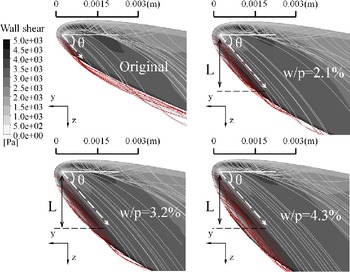
To explain the reason for the inflection point at w/p = 2.1% in Fig. 16, the contours of wall shear near the leading edge on the tip of the original blade, and blades with w/p = 2.1%, w/p = 3.2% and w/p = 4.3% are shown in Fig. 17. The trace of SHV is labeled with white dash arrow, and the angle of this trace is labeled as ‘θ’, measured from the streamwise direction. The strength of SHV can be characterised by the value of wall shear. To illustrate the vortexes on the tip, red streamlines are released from the suction side of leading edge to show SHV, and the gray ones are released from the pressure side of leading edge to show PHV.
Contours of wall shear on blade tip.

From Fig. 17, for all blades, the distribution of SHV strength keeps a high similarity in a same normal distance, and the SHV evolves in a nearly equal direction. The evolution of SHV is mainly driven by the flow from the pressure side due to shearing, and near the pressure side, the flow angle and wall shear in the blade with winglet keep nearly the same as that in the original blade. This implies that the driving force of turning the SHV in the blade with winglet keeps nearly the same as the one in the original blade. Thus, for all blades, the distribution of SHV strength keeps a high similarity in a same normal distance. However, it should be noted that, for blades with different winglet widths, some slight differences in distributions of SHV strength are still observed. This is mainly because the velocity and pressure fields near the suction side leading edge are changed by different winglet profiles.
A closer inspection of Fig. 17 shows that the strengths of SHV in blades with w/p = 3.2% andw/p = 4.3% start to decrease after a normal distance equal to L (labeled in Fig. 17). This normal distance is also equal to that of the blade with w/p = 2.1%. The decrease of the strength of SHV is mainly resulted from the conflict between the flow from the suction side and the one from the pressure side. The flow from the suction side is supplied into SHV with negative streamwise vorticity. On the contrary, the flow from the pressure side with positive streamwise vorticity weakens the strength of SHV. After the normal distance equal to L, the latter factor surpasses the former factor, and hence the strength of SHV starts to decrease.
As an important effect of this decay of the SHV, the interaction between the SHV and the leakage vortex is weakened. This is evidenced by the rapid reduction of the slope of streamwise vorticity decrement after w/p = 2.1% in Fig. 16. The decay of the SHV is also responsible for the inflection point at w/p = 2.1% of the increment of efficiency in Fig. 8, since the weakening effect of SHV on the strength of leakage vortex is a crucial contributor for the increment of efficiency.
6.2 Effect of winglet width on heat load
The winglet increases the blade surface area, and therefore it tends to increase the blade heat load. This section will examine the relation between the winglet width and the blade heat load, and then analyse the distribution of heat flux over the blade surface.
Figure 18(a) shows the relation between the winglet width and the normalised blade surface area increment, and Fig. 18(b) shows the relation between the winglet width and the normalised heat load increment which is defined as Equation (13). It should be noted that, the blade surface area, used to calculated the heat load, includes the surface area of pressure side, suction side and tip, that is, the whole blade surface. In each plot, a linear fitting through least square method is marked with a red dash straight line. The linear determination coefficient and slope of the straight line are also marked.
Blade surface area and heat load versus w/p. (a) Blade surface area versus w/p, and (b) heat load versus w/p.

 \begin{align}\Delta H^{\ast} = {{{H_{Imroved}} - {H_{Original}}} \over {{H_{Original}}}} = {{\int\limits_{Improved} {qdA} - \int\limits_{Original} {qdA} } \over {\int\limits_{Original} {qdA} }}\end{align}
It is found that, the winglet increases the blade surface area and the heat load. The linear determination coefficient for each plot exceeds 0.99, indicating that the relation between blade surface area increment and winglet width and the relation between heat load increment and winglet width are approximately linearity. This implies that, the increase of blade surface area due to the winglet might be an important contributor for the heat load increment.
To further analyse the effect of winglet on heat load, the contours of surface heat flux on the blade tip and suction side surface are shown in Fig. 19. The original blade and the blade with w/p = 2.1% are chosen for comparisons.
Heat flux on tip and suction side surface. (a) Original, and (b) w/p = 2.1%.

From Fig. 19, on the blade tip surface, the high heat flux region is related to the development of pressure arm of tip leading edge horseshoe vortex (PHV) and the suction arm of tip leading edge horseshoe vortex (SHV), as mention in Section 6.1. The high heat flux related to PHV and SHV reduces along streamwise direction due to the flow acceleration. The region near the SHV in the blade with w/p = 2.1% shows a longer distance due to the winglet.
From Fig. 19, on the suction side surface, there is a reduction of heat flux on the region from leading edge to mid-chord at about 90% span for the w/p = 2.1% blade. This is because, the winglet of the w/p = 2.1% blade puts the leakage vortex more far from the suction side surface, as seen from Fig. 12, and the interaction between leakage vortex and suction side boundary layer is weaker, reducing the heat flux through the suction side surface. The rest regions are similar for both blades. Combined with the finding from Fig. 18(b), it could be concluded that, even though the winglet can put the leakage vortex far from the blade to reduce the heat flux in a small region, this reduction of heat flux is smaller than the increment of heat flux due to the increased blade surface area, leading to a net increment of heat flux.
Except for the above differences, the distributions of heat flux on the tip surface and suction side blade surface of these two blades show a similar pattern.
6.3 Trade-off between efficiency and heat load
From Section 6.1 and Section 6.2, it is found that, as the winglet width increases, the efficiency is improved at the expanse of a more severe heat load. Further, the main factors responsible for the increment of efficiency and that of heat load have been revealed. In the Section 6.3, the design space of the winglet width will be explored based on a point view of the trade-off between the efficiency and the heat load.
Since the increment of efficiency is a positive effect of the winglet and the increment of heat load is a negative effect, this paper defines a ratio of the increment of efficiency to the increment of the normalised heat load (Δη/ΔH*), Equation (1) divided by Equation (13), in order to quantify the trade-off between the efficiency and the heat load. The higher value of Δη/ΔH* means that more increment of efficiency is achieved at the expanse of per unit increment of heat load, that is, a better choice of winglet width for the winglet design in the present paper. The Δη/ΔH* versus w/p is plotted in Fig. 20.
Trade-off relation between efficiency and heat load.

It is found that, the Δη/ΔH* gradually changes above 0.65 before w/p = 2.1%, but dramatically drops below 0.65 after w/p = 2.1%. This means that, after w/p = 2.1%, at the expanse of each 1% heat load increment, the efficiency improvement is less than 0.65%.
This dramatic drop of Δη/ΔH* after w/p = 2.1% in Fig. 20 is mainly resulted from the same inflection point of efficiency increment in Fig. 8. For the increment of heat load it keeps a great linear relation with the w/p(from Fig. 18(b) in Section 6.2), because it is primarily driven by the increment of the blade surface area due to the winglet. For the increment of the efficiency, however, it inflects down from the linear relation after w/p = 2.1%(from Fig. 8 in Section 6.1). This inflection point of efficiency improvement may be attributed to the reduction in the strength of SHV, as explained in Section 6.1.
In summary, even though the efficiency monotonically increases with the winglet width, the inflection point at w/p = 2.1% limits the increment of efficiency at the expense of per unit increment of heat load. The ZISTR designed with the winglet width equal to 2.1% blade pitch achieves a great trade-off between efficiency and heat load that the efficiency is improved by 0.85% at an expense of 1.2% increment of the heat load.
6.4 Effect of winglet on blade weight and mechanical stress
Winglets are small plates extending from the tip of the blade. This would add the blade weight and affect the mechanical performance of the rotor, which would prevent to implement these winglets. In this section, the effect of winglet on blade weight and mechanical stress are discussed. Based on the maximum working temperature of the ZISTR, that is 1200K, K465 superalloy is chosen as the material of the ZISTR for the mechanical simulation in this investigation. Since the blade with winglet of w/p = 2.1% has been proved to be a great design from Section 6.3, the original blade and the blade with winglet of w/p = 2.1% are chosen for comparisons in this section.
The weights of single blade of the original blade and the blade with w/p = 2.1% are listed inTable 3. The winglet of w/p = 2.1% increases the blade weight by about 0.183%, from 32.71g to 32.77g. To eliminate the added weight resulted from winglet, there are some ways, such as decreasing the blade numbers, reducing the blade chord length and so on. For simplicity, the way of reducing the blade chord length is chosen for investigation in this paper. To obtain a reduced-chord blade, the blade geometry is scaled down at the same proportion in axial direction and it is kept unchanged in spanwise direction. After some trials, it is found that, the blade with w/p = 2.1% reduced by 0.174% of chord length has the same weight as the original blade, as listed in Table 3. The efficiency of the reduced-chord blade with w/p = 2.1% decreases by 0.05%, from 84.16% to 84.11%. This decrement of efficiency is acceptable because the efficiency of reduced-chord blade with w/p = 2.1% is still higher than that of the original blade by 0.8%. Thus, the added blade weight caused by the winglet on the blade with w/p = 2.1% could be eliminated by means of reducing the blade chord length by 0.174%, and the efficiency improvement decreases from 0.85% to 0.8%.
Blade weight and turbine efficiency

To quantify the effect of the winglet on the blade mechanical stresses, a static structural analysis has been performed on the original blade and the blade with w/p = 2.1%. The ANSYS Workbench Static Structural Analysis is employed for mesh generation and finite element analysis. To simplify the structure modeling, the blade and its disk are assumed to be integrated into a turbine disk. A 1/18th sector of the turbine disk is created based on the blade number, as shown in Fig. 21. On the frame of reference, displacement constraints in axial and tangential directions are applied to the surface marked with dash circle in Fig. 21. Three different kinds of loads have been applied, including: 1) a centrifugal load resulting from rotational speed, 2) an aerodynamic load extracted from the blade surface pressure, and 3) a thermal load decided by the blade surface temperature. The Von Mises stress distributions on the suction side and hub surface are shown in Fig. 22.
Blade models for finite element analysis.

Von Mises stress distributions on blade surface.

From Fig. 22, it is found that the distributions of Von Mises stress on the suction side and hub surface of these two blades are similar. The maximum of stress appears at the blade root near the leading and trailing edge, marked with dash circles. To quantify the difference between the original blade and the blade with w/p = 2.1%, the distributions of Von Mises stress at the blade root and the 95% blade span are plotted in Fig. 23. The blade root is chosen to compare the maximum value of the Von Mises stress. The 95% blade span is chosen, because it is near the interface between the winglet and the blade.
Von Mises stress at the blade root and 95% blade span. (a) Blade root, and (b) 95% blade span.

From Fig. 23, the distributions of Von Mises stress at the blade root of these two blades are nearly the same. The maximum of the Von Mises stress is below 750Mpa, which is under the allowable stress of K465 superalloy. At 95% blade span, before 50% blade chord, the Von Mises stress of the blade with w/p = 2.1% is higher than that of the original blade by only about 2Mpa, which is acceptable for the engine application [Reference Zhou and Zhong23]. Thus, for blade with w/p = 2.1%, the added mechanical stress due to the centrifugal, aerodynamic and thermal load may not pose a severe problem for its application.
7.0 Conclusions
In a zero inlet swirl turbine rotor (ZISTR), the tip leakage vortex takes up more than 1/3 blade span at the rotor exit, generating a large amount of losses. To reduce the leakage flow loss and improve the efficiency of the ZISTR, a front suction side winglet is employed on the blade tip in the present paper. The effect of winglet width on the aero-thermal performance of the ZISTR is investigated by numerical simulations to explore the design space of the winglet width of the suction side winglet. Besides, the effect of winglet on blade weight and mechanical stress is evaluated to validate that the mechanical performance of ZISTR using suction side winglet could be acceptable for engine application.
It should be noted that, suction side winglets for traditional unshrouded turbine rotors with deflection angles larger than 10 degrees, have been investigated by many researchers. In the traditional turbine rotor, there usually exists the passage vortex. In many cases of traditional turbine rotors using the suction side winglet, this winglet usually not only reduced the mass flow of tip leakage flow but also eliminated the loss caused by the passage vortex, thereby improving the turbine efficiency. However, for the ZISTR, there is no obvious passage vortex due to its deflection angle less than 0.5 degree. Hence, for this kind of turbine rotors with small deflection angle (less than 0.5 degree) using suction side winglet, the mechanism and effectiveness of the loss reduction are still not clear and these have been investigated in the present work. Especially, a suction side leading edge horseshoe vortex (SHV) formed on the tip surface near the leading edge, has been reported in some previous studies, but there are few published literatures concerning the effect of winglet width on the SHV and then on the leakage flow loss, which has been explored on the ZISTR using suction side winglet in the present work.
The primary conclusions of the present work are summarised as follows:
-
As the winglet width increases, the leakage flow loss is reduced and the efficiency is improved. This is mainly attributed to the SHV. This SHV rotates in the reverse direction to the leakage vortex, so it tends to break the formation of the leakage vortex near the front part of suction side, thereby mitigating the leakage flow loss. With a larger winglet width, the SHV stays longer time on the blade tip and leaves it at a further downstream location. This increases the time and the contact area of the interaction between the SHV and the leakage vortex, so the leakage vortex is further weakened.
-
The increase of winglet width also results in a more severe heat load. Although the winglet can put the leakage vortex far from the blade, avoid the interaction between the leakage vortex and the boundary layer of the blade surface, and reduce the heat flux in a small region, this reduction of heat flux is smaller than the increment of heat flux due to the increased blade surface area, leading to a net increment of heat flux. The increase of heat load keeps a great linear relation with the winglet width. For the cases investigated in the present work, the linear determination coefficient exceeds 0.99.
-
Once the winglet width exceeds a certain value, less increment of efficiency is obtained at the expense of per unit increment of heat load. This is primarily because, the SHV gradually decays on the blade tip with an relatively large winglet width and, therefore, the interaction between the SHV and the leakage vortex is weakened. For the cases investigated in the present work, this winglet width is equal to 2.1% blade pitch. With this winglet width, the efficiency is improved by 0.85% at an expense of 1.2% increment of the heat load.
-
For the blade with winglet width of 2.1% blade pitch, the added blade weight caused by the winglet could be eliminated by means of reducing the blade chord length by 0.174%, and the efficiency improvement decreases from 0.85% to 0.8%. Besides, for the blade using this winglet, the added mechanical stress due to the centrifugal, aerodynamic and thermal load is acceptable for the engine application.
In summary, for the ZISTR using suction side winglet, a larger winglet width helps to enhance the interaction between the SHV and leakage vortex and then the strength leakage vortex is weakened, which improves the turbine efficiency. Once the winglet width exceeds a certain value (this value is equal to 2.1% blade pitch for the cases investigated), the SHV gradually decays, and the increment of efficiency decreases. On the other side, as a negative effect resulted from the winglet, the heat load increases with the winglet width due to the increased blade surface area for heat transfer. Based the cases of ZISTR investigated in the present work, the winglet width of 2.1% blade pitch is a great choice from a point view of the trade-off between efficiency and heat load, and the mechanical performance of ZISTR with winglet width of 2.1% blade pitch is validated by numerical methods and it is acceptable for engine application.
To generalised these findings towards other turbine rotors with low blade deflections using the suction side winglet, even though the exact values of the winglet width, efficiency, heat load could change, the understandings of the effect of winglet on the flow and heat transfer still could be good guidelines, as following:
-
The SHV could be a dominated flow structure mitigating the strength of leakage vortex and then improving the turbine efficiency. If so, the variation of the efficiency with winglet width and that of the strength of SHV with winglet width could be similar. This should be noticed and verified by the designers when they inspect the flow filed inside the gap tip.
-
The increased blade surface area resulted from the winglet would increase the area for heat transfer, and it might be a major factor contributing to the heat load increment. If so, the designers can consider a better geometry of suction side winglet with a smaller surface area at the same winglet width.
In the future research, other geometric parameters of the suction side winglet would be studied, for example, the axial length of the winglet. And further investigations on the squealers or the combinations of squealers and winglets for the ZISTR are still necessary.
Acknowledgments
This work was supported by the National Science and Technology Major Project(2017-III-0010-0036) and the National Natural Science Foundation of China (No.51776198).