1. INTRODUCTION
Computer-aided design (CAD) tools for solid modeling are a pivotal component of engineering design as they provide the means to rapidly create and visualize product ideas in the digital environment. In current geometric CAD tools, hierarchical constructive solid geometry (CSG; Requicha & Voelcker, Reference Requicha and Voelcker1983) has been a dominant approach due to its many advantages. Specifically, CSG allows a hierarchical construction of geometries through a sequence of primitive operations applied to simple initial shapes. This sequential structure enables subsequent alterations to be easily made on the parameters of the initial shapes as well as the applied operations themselves, all without requiring much manual intervention.
Although CSG is useful for creating models composed of primitive geometries, typical models encountered in industrial design require more advanced approaches capable of representing and manipulating free-form surfaces. The nature of such models typically necessitates a local and progressive design of the different regions that does not conform to an underlying construction hierarchy. This makes alterations to the design (be it for specific design changes or conceptual form exploration) difficult to administer, as the designer needs to closely monitor the affect of a particular modification on the rest of the design.
Similarly, this local progression often forces the design to be well thought out in advance before digital modeling begins. In the absence of a global underlying shape(s) often available in CSG, shape design without such visual references is nontrivial, as the design has to evolve in a spatially decoupled, exploratory manner spanning a multitude of detail levels (Maher & Poon, Reference Maher and Poon1996). This forces the designer to employ other forms of references such as previously created sketches. However, even with these references, shape modification specifically is a laborious process as intended alterations may not match the level of detail present in the model. This issue is most prominent in cases where major shape changes are planned to an existing model. Volumetric editing tools, such as free-form deformation (MacCracken & Joy, Reference MacCracken and Joy1996), require the creation of suitable deformation lattices that need to be separately designed. Likewise, methods involving push and pull operations, or skeleton based approaches typically minimize energy functionals that are strongly related to the existing levels of surface detail. As a result, geometry editing at an arbitrary but user controllable level of granularity remains a significant challenge.
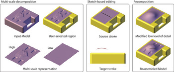
In this work, we propose a free-form surface editing method that enables a sketch-based editing of polygonal geometries at varying levels of detail. At the heart of the proposed approach lies a multiscale representation of the geometry achieved through a spectral analysis on the free-form surface. This representation is accompanied by a sketch-based surface editing algorithm that enables modifications at different geometric levels. The main advance is thus the ability to represent the original geometry in increasingly simpler forms, and make geometric changes at a detail level commensurate with the design intentions. With the proposed approach, designers can create and navigate several versions of the original model through a spectral analysis, and make edits at any desired level while preserving the original topology (Fig. 1). This in turn enables the designer to view and impart large-scale alterations to a suitably simpler representation of the original geometry, thereby eliminating the need for explicit detail management. Moreover, the seamless unification of modifications applied at different levels, and the automatic reconstruction of the final shape, help the designer focus on the immediate concerns of the design progressively, while temporarily isolating the noncritical aspects both visually and geometrically.
With the proposed method, the designer works from a product geometry and makes modifications at a desired level of detail using a multiscale representation. This allows new forms to be generated from existing models while preserving the desired features. [A color version of this figure can be viewed online at http://journals.cambridge.org/aie]

2. OVERVIEW AND USER INTERACTION
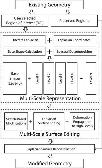
The proposed method consists of (1) A spectral geometry representation for triangular meshes that allows a shape to be represented at different levels of detail, while preserving the original topology, and (2) a sketch-based geometry modification method that allows users to alter the geometry at a desired level of detail without disrupting the existing shape features. Figure 2Footnote 1 illustrates the major components of our approach. The first stage is the definition of a multiscale representation of free-form meshes through a spectral analysis on the discrete Laplacian operator. The result of this spectral analysis is a set of shapes each of which expresses the given geometry at a particular scale. At a user-selected region of interest (ROI), these spectral layers are combined with a curvature variation minimizing base shape to form the multiscale representation. The second component involves a sketch-based editing method applicable to different layers and the propagation of deformations across the layers. Sketch-based modifications are applied using Laplacian surface editing (LSE) and the modifications at that particular level are propagated to the remaining levels thereby enabling the reconstruction of the final geometry.
The components of the proposed method: (1) multiscale representation and (2) multiscale surface editing.

In a typical scenario, the user starts by demarcating a ROI on the original design by circling the region with a lasso tool. The ROI is then decomposed into a base shape and a number of spectral components at various levels of detail using the multiscale representation. Through a slider, the user can navigate the various levels of detail displayed at the ROI. At a suitable level of choice, the user sketches source curves on the surface that represent free-form deformation handles. The user then sketches the target shapes of the source curves from a desired viewpoint. The surface is deformed using LSE such that the source curves on the surface match their target shapes and positions in the same viewpoint. Once the deformed surface is calculated, the temporarily isolated features are added back to the ROI with orientation adjustments as necessary. Finally, combining the level at which the shape was deformed and the additional levels representing the features, the final geometry is synthesized using a least squares Laplacian reconstruction. This process is repeated as many times as desired until the user edits the geometry into the final form.
3. RELATED WORK
3.1. Hierarchical shape design
Hierarchical approaches in shape design emerged in the early 80s, and have proved valuable as they enable the creation of shapes and associated manipulation methods in which changes to the geometry can be administered and propagated properly (Requicha & Voelcker, Reference Requicha and Voelcker1983). Mantyla and Sulonen (Reference Mantyla and Sulonen1982) first proposed a hierarchical solid modeling system where they utilize atomic functions called Euler operators (Baumgart, Reference Baumgart1974; Wilson, Reference Wilson1985). Their approach involved a sequential construction of solid models, while allowing manipulations to be made on the operations at all levels of the modeling history. Requicha and Voelcker (Reference Requicha and Voelcker1985) used hierarchical Boolean operations on boundary representation schemes and achieved more advanced manipulations. Based on cell complexes, Masuda (Reference Masuda1993) used Boolean operations for manipulating nonmanifold geometries in a hierarchical manner. Similarly, Morse operators leveraged the modeling of 3-manifolds through a systematic multilevel approach (Lopes & Tavares, Reference Lopes and Tavares1997). Deformations and modifications to existing boundary representation elements (Raghothama & Shapiro, Reference Raghothama and Shapiro1998) further increased the freedom in the creation and modification of models. These methods are mostly suitable for engineered parts exhibiting regular features and primitives and related optimization applications (Falk et al., Reference Falk, Barthold and Stein1999). The creation and editing of organic free-form surfaces commonly observed in industrial design applications, however, is much more challenging. Our approach focuses on the modification of such free-form surfaces. Specifically, we describe a method to decompose existing geometries into multiple levels detail that facilitates visualization and editing at a variety of detail levels. This approach enables editing of free-form surfaces at coarse and fine level details, without the need for a hierarchical construction or feature history.
3.2. Multiresolution mesh editing methods
Early multiresolution mesh editing techniques used signal processing approaches (Taubin, Reference Taubin1995) and subdivision methods (Zorin et al., Reference Zorin, Schröder and Sweldens1997; Kobbelt et al., Reference Kobbelt, Campagna, Vorsatz and Seidel1998). Guskov et al. (Reference Guskov, Sweldens and Schröder1999) combined the approaches by Zorin et al. (Reference Zorin, Schröder and Sweldens1997) and Kobbelt et al. (Reference Kobbelt, Campagna, Vorsatz and Seidel1998) into one multiresolution editing method applicable to irregular meshes. Since then a multitude of multiresolution mesh editing methods have been presented. Alexa (Reference Alexa2003) proposed using differential coordinates for smooth deformations, and Sorkine et al. (Reference Sorkine, Cohen-Or, Lipman, Alexa, Rössl and Seidel2004) extended this method to achieve more meaningful, elastic deformations. Similarly, Yu et al. (Reference Yu, Zhou, Xu, Shi, Bao, Guo and Shum2004) used the Poisson equation to diffuse the transformations on local frames and reconstruct the surface under these transformations. Zayer et al. (Reference Zayer, Rössl, Karni and Seidel2005) calculated a harmonic guidance field to guide a model-specific diffusion for the deformations. Zhou et al. (Reference Zhou, Huang, Snyder, Liu, Bao, Guo and Shum2005) used a volumetric graph Laplacian to achieve volume aware deformations. Von Funck et al. (Reference Von Funck, Theisel and Seidel2006) proposed using a time dependent vector field to achieve volume preserving, non-self-intersecting deformations. Shi et al. (Reference Shi, Yu, Bell and Feng2006) developed a multigrid deformation method that can efficiently process large models. Huang et al. (Reference Huang, Shi, Liu, Zhou, Wei, Teng, Bao, Guo and Shum2006) presented a general framework for constrained mesh deformations with gradient domain techniques. Botsch et al. (Reference Botsch, Pauly, Gross and Kobbelt2006) proposed using coupled prisms for intuitive surface modeling. In all the above methods, the multiscale editing of free-form surfaces are calculated using the original, high-resolution representation of the surface. In this work, we extend the previous approaches to enable multiscale viewing and editing, thereby providing a richer set of interaction and modification tools to the user.
4. BACKGROUND
Before detailing our approach, we briefly describe the mathematical foundations based on the Laplacian coordinates underlying our method. In the following sections, we first describe the discrete Laplacian operator, and then describe the geometric reconstruction and surface editing methods using the Laplacian coordinates. In Section 5 we describe the multiscale representation of geometries and the adaption of the LSE methods into our sketch-based, multiscale, shape exploration method.
4.1. Laplacian coordinates
As described previously, early detail preserving mesh editing techniques utilized existing subdivision algorithms to achieve deformations at different levels of details defined at different levels of subdivisions. Majority of the recent work focuses on “intrinsic surface deformation” (Sorkine, Reference Sorkine2006) since first introduced by Alexa (Reference Alexa2003). These approaches encode the geometry with differential coordinates defined as displacement vectors relative to their local frames, as opposed to encoding the geometry in the global coordinate system.
The differential coordinate,  , represents the position of a vertex relative to the positions of its one-ring neighbors on the mesh. The earlier forms of the differential coordinate used the barycenter of the one-ring neighbors calculated using a weighting scheme:
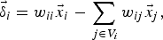
where the vertices in the one-ring of the ith vertex is denoted by the set of indices V i. In a uniform weighting scheme, the associated weights for the ith vertex and its neighbors are w ii = 1 and w ij = –1/N, respectively where N is the number of vertices in V i. Subsequent applications utilized more precise schemes that use the geometry information alongside with the topology of the mesh (for an extensive review, see Wardetzky et al., Reference Wardetzky, Mathur, Kälberer and Grinspun2008). Among the existing ones, the most commonly used method is the cotangent scheme (Meyer et al., Reference Meyer, Desbrun, Schröder and Barr2002), and it is defined by the following weights:
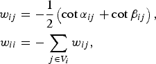
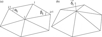
where αij and βij are the angles facing the edge between vertices i and j in opposing triangles as shown in Figure 3a.
(a) The angles used in the cotangent weighting scheme of the discrete Laplacian. (b) The resulting Laplacian coordinates are aligned with the approximated curvature.

The differential coordinates calculated with the cotangent scheme are parallel to the estimated surface normal at each vertex (Fig. 3b). Moreover, when the weights calculated in Equation 2 are scaled by the inverse Voronoi area, the lengths of the Laplacian coordinate vectors approximate the mean curvature of the surface (Meyer et al., Reference Meyer, Desbrun, Schröder and Barr2002). This area-weighted version of the cotangent scheme corresponds to the discrete Laplace–Beltrami operator defined on a discrete manifold mesh, thus the resulting differential coordinates attain the name Laplacian coordinates. We can collect the equations of the individual vertices into a matrix form as

where [L] is an n × n Laplacian matrix for a mesh consisting of n vertices, δ and x are the n × 3 Laplacian and Cartesian coordinates in the matrix form, respectively (columns corresponding to the x, y, z components).
4.2. Laplacian reconstruction
Because the Laplacian operator encodes the position of each vertex relative to its one-ring neighborhood, a forward calculation of the Laplacian coordinates using Equation 3 loses the absolute position of the object in the global coordinate frame. As a result, the Laplacian matrix is rank deficient and solving for a unique set of positions, x, requires constraints. Specifying the position of one vertex is sufficient for a full recovery of the mesh vertex positions as

where  is the prescribed position of a constrained vertex
 . Solving Equation 3 for a given δ under the above constraint yields the full set of vertex positions.
In the remainder of the text, the prime notation as in  is used to denote the newly computed positions of the associated coordinates following a deformation. For constrains as in
 , it represents the prescribed new coordinates of the associated vertices that are different than their original coordinates.
4.3. LSE
Using multiple constraints in the form of Equation 4 it is possible to edit free-form meshes as proposed in Alexa (Reference Alexa2003) provided that the modifications are applied locally. The error functional associated with the least squares problem of the edited system with a set of constraints is as follows:

where  are the vertices in the mesh and
 are the vertices for which constraints are prescribed. The solution to this minimization is determined through the following least squares problem:
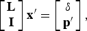
where I is a c × n matrix with entries equal to 1 for the corresponding constrained vertices and 0 otherwise, p′ is a c × 3 matrix of the prescribed geometric constraints for c vertices. Large deformations applied with this scheme typically result in undesired distortions to small features and details, as well as a poor quality mesh. A partial remedy to this problem is to propagate the local transformations resulting from the constraints across the mesh (Sorkine et al., Reference Sorkine, Cohen-Or, Lipman, Alexa, Rössl and Seidel2004):

where Ti( ) is the transformation matrix that transforms the ith vertex and its one-ring neighbors into their deformed coordinates, and it is written as a function of the unknown final coordinates
 (Sorkine et al., Reference Sorkine, Cohen-Or, Lipman, Alexa, Rössl and Seidel2004). When rotations are involved, T i is not a linear function of the deformed coordinates. However, assuming small rotations, T i can be written in a linear form. The final form of Equation 7 then becomes a quadratic function of the deformed coordinates
 , and thus the minimizer will be a linear function of
 resulting in a linear least squares optimization. Please refer to Sorkine et al. (Reference Sorkine, Cohen-Or, Lipman, Alexa, Rössl and Seidel2004) for details. With this new linearized error, the amount of rotations and scalings is minimized in the least squares sense, as opposed to minimizing the total amount of positional errors in Equation 5. This formulation leads to a modified Laplacian operator LLSE in which transformations T i are linear function of
 and can be computed in the least squares sense given the original mesh and the prescribed constraints. This in turn results in intuitive and natural deformations while preserving surface details. Computationally, this approach leads to the solution of
 as follows:
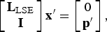
where LLSE is the modified Laplacian computed from the original mesh and the prescribed constraints and p′ is the matrix of prescribed geometric constraints.
5. TECHNICAL APPROACH
In the previous section, we provided an overview of the discrete Laplacian operator, the Laplacian coordinates, and related reconstruction and editing applications. In this section, we describe the two major components of the proposed approach: (1) multiscale representation of free-from meshes and (2) multiscale surface editing and deformation propagation across scales.
5.1. Multiscale representation of free-form meshes
Our multiscale representation of free-form meshes of arbitrary topology is based on a local spectral analysis on the discrete Laplacian operator. We achieve this by first calculating a base shape defined in the ROI, which minimizes the total variation of curvature across its surface. This shape represents a simple underlay over which additional features can be added. Using a local spectral analysis, we then calculate a set of mode shapes that represent the features on the original mesh at a variety of different spectral scales. The surface in the ROI can then be reconstructed as a linear combination of these mode shapes and the base. This approach allows the surface features to be temporarily removed from the surface, thereby allowing the designer to make large scale edits to the underlying geometry without being concerned with the preservation of these features during editing. Later, these features can be placed back onto the modified geometry. Note that the user can determine what is considered a base shape versus a feature using a single parameter and can dynamically change this parameter to make edits at various levels of detail. We first describe the base shape calculation and the subsequent spectral analysis, and then define a level of detail measure that is closely connected to the scale of the features that can be represented in a geometry.
5.1.1. Calculation of the base shape
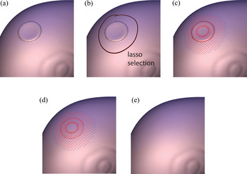
The intended ROI is demarcated by the user by circling the region with a lasso tool from a user picked viewpoint (Fig. 4b). The vertices on the mesh that are encircled by the recorded lasso stroke are identified by converting the stroke into a closed polygon that occludes the intended region. The vertices that fall into the polygon in this particular viewpoint are then identified through occlusion queries.Footnote 2
Calculation of the base shape in the user selected region of interest. (a) The region containing features (b) are selected by the user by a lasso tool. (c) The vertices in the region and the surrounding edge vertices are highlighted in red and blue, respectively (online only). (d) The calculated base shape shares the same topology, (e) resulting in a smooth base shape that minimizes its total variation of curvature. [A color version of this figure can be viewed online at http://journals.cambridge.org/aie]

At the user-specified ROI, we first calculate a base shape that minimizes the variation of curvature, and thus is devoid of small-scale features. Our approach is similar to the method of free-form surface fairing presented by Schneider and Kobbelt (Reference Schneider and Kobbelt2001). Similarly, we solve two problems; one with curvature boundary conditions, and one with positional constraints.
As mentioned earlier, the discrete Laplacian operator calculated using the area weighted cotangent scheme estimates the discrete mean curvature at the surface vertices. The curvature variation across the surface is minimized by setting the Laplacian of the curvature to zero as

For the solution of the above equation, the discrete Laplacian operator and the Laplacian coordinates modified by the area normalized cotangent scheme is used to solve the above equation. For a user-specified ROI (an example is shown in Fig. 4b), the outer one-ring neighboring vertices surrounding the ROI are used as the boundary positions for the solution.
The rows and columns of the Laplacian matrix that correspond to the vertices in the ROI and its boundary are collected into partial Laplacian matrices, LROI and LBV, respectively. Note that, to obtain a suitable smooth base surface, the Voronoi area normalized cotangent weighting (Equation 3) should be used for the discrete Laplacian. Here, the previously calculated Laplacian coordinates at the boundary vertices, δBV, are kept fixed, and the Laplacian coordinates representing the base surface at the ROI vertices, δbaseROI, are calculated by solving the following least squares problem (by extending Equation 9)

where δbaseROI and δ′BV are the Laplacian coordinates at the ROI and its boundary, respectively. Once the base shape is determined in terms of the Laplacian coordinates, the actual positions of the ROI vertices are determined by solving Equation 6. This local treatment of the base shape is computationally more efficient than a global analysis as using partial matrices significantly reduces the computational cost. We provide example computation performances in Section 6.
An example base shape is shown in Figure 4. The user-selected ROI (Fig. 4b) is filtered to obtain a smooth surface that is devoid of any small-scale features (Fig. 4d,e). This base shape constitutes the basis of our multiscale representation.
5.1.2. Spectral analysis on the Laplacian
As described earlier, we calculate the mode shapes using a spectral analysis on the discrete Laplacian operator. This analysis is at the hearth of our multiscale geometric representation as the resulting mode shapes can express the geometry at a spectrum scales.
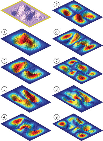
Similar to the base shape calculation, we first extract the portion of the discrete Laplacian matrix which corresponds to the vertices in the ROI into a partial Laplacian matrix, LROI. An eigen analysis on the partial Laplacian yields a set of eigenvectors, suitably called the mode shapes, and associated eigenvalues. We use the term mode shape due to the analogy between the discrete Laplacian matrix and the system matrices typically seen in transverse vibrations of thin plates. In the context of vibrations, the discrete Laplacian matrix of the mesh corresponds to M−1K, where M and K are the mass and stiffness matrices of the thin plate. This similarity is also seen in the results of the eigen analysis. Figure 5 shows the first nine mode shapes of an example surface mesh fixed at its edges (i.e., the ROI is the region encircled by the boundary). The mode shapes calculated from the discrete Laplacian matrix closely resemble the mode shapes of a plate fixed at its edges.
The first nine mode shapes of a model that is fixed at its edges (drawn with yellow color online only). The colors in the online only version denote the magnitude of the mode shape. The shape numbers increase with increasing eigenvalues. Note that as the shape number increases, the size of the isolated regions decreases. Thus, the lower and higher modes can express larger and smaller scale features naturally. [A color version of this figure can be viewed online at http://journals.cambridge.org/aie]

The mode shapes shown in Figure 5 are ordered with respect to their eigenvalues in an increasing fashion. Lower modes exhibit sign changes in a few large regions, whereas the higher modes exhibit changes in a number of smaller regions. This property allows the mode shapes to describe the geometry of the plate as the superposition of various components that can represent different scales.
5.1.3. Linear superposition of the base shape and the mode shapes
Once we calculate the base shape and the mode shapes, we construct our multiscale representation as a linear combination of these shapes. We decompose the ROI into the base shape and the remaining features described in a multitude of spectral scales. We adjust the number of participating modes in the reconstruction by truncating the higher eigenvalue modes to achieve representations of the ROI at different scales.
For this, we first calculate the residual Laplacian coordinates at the ROI as

Note that δROI are the Laplacian coordinates computed from the original vertex positions in the ROI and the Laplacian matrix LROI, which represents the Laplacian operator associated with the ROI. For an ROI containing m vertices, LROI is an m × m matrix. Using an eigenanalysis, we obtain the first k eigenvectors of LROI as an m × k matrix ϕlowROI corresponding to the k smallest eigenvalues. Calculating

where + is the Moore–Penrose pseudoinverse operator. The low-level detail components of the ROI, δlowROI is then computed as

Then the higher level of detail components are calculated and stored as

Finally, the resulting editable Laplacian coordinates of the ROI, δedtROI, is formed by the following summation:

The absolute coordinates of the geometry at this level is then calculated via Laplacian reconstruction given in Equation 6 by fixing the coordinates of the non-ROI vertices at their original positions.
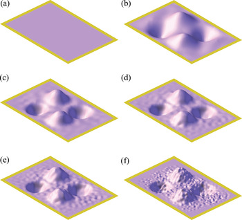
Figure 6 shows example reconstructions of the surface given in Figure 5 using different number of modes. Note that the scale of the smallest detail that can be represented decreases in size as the number of retained modes increases. This ability to represent features at different scales enables a true multiscale visualization and interaction with the geometry using existing sketch-based mesh editing tools.
The surface in Figure 5 represented at different levels of details starting from (a) the base shape to (f) the full model. The region of interest is surrounded by the fixed region drawn in yellow (online only version). (b–e) The surfaces are constructed using (b) 50, (c) 250, (d) 500, and (e) 750 modes. Note that the scale of the smallest detail that can be represented decreases in size as the number of retained modes increases. [A color version of this figure can be viewed online at http://journals.cambridge.org/aie]

5.1.4. Level of detail
As described, the size of the finest detail represented in the ROI can be controlled by adjusting the number of modes retained. Although this number directly dictates the resulting level of detail, it does not automatically correspond to a geometric scale in the model due to a complex relationship between the index of a mode and the finest detail that can be captured by that mode shape.
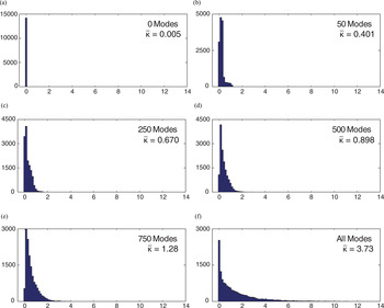
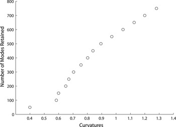
To formulate a reliable and congruent metric, we utilize the curvature histograms of various levels of detail that can be reconstructed using different numbers of modes. The curvature histogram reliably shows the curvature rangeFootnote 3 that covers the majority of the surface for a given number of modes. Figure 7 shows several histograms of reconstructed surfaces previously shown in Figure 6. An important observation is that the curvature range monotonically becomes narrower around smaller curvature values as the number of retained modes decreases (Fig. 8). Thus, the upper limit of this range attains values between the limit calculated from the base shape (the lowest) and the limit calculated from the original model (the highest). From this observation, we define the level of detail parameter, ηLoD to be a number in [0, 1] which linearly controls the limit curvature value  as

where and are the limiting curvatures of the base shape and the original shape, respectively. For a given value of ηLoD, the number of required modes can be determined either by solving a search problem, or using a range of precalculated values as illustrated in Figure 8.
The curvature histograms of shapes shown in Figure 6a–f. Each histogram shows a cutoff curvature value that is larger than the majority of the calculated discrete curvatures. [A color version of this figure can be viewed online at http://journals.cambridge.org/aie]

The relationship between the number of retained modes (hence, the cutoff frequency) and the number of modes used to reconstruct the shape shown in Figure 6. Note the monotonicity of the curvatures with the increasing number of modes. This relationship enables a curvature-based control on the level of detail through the number of modes retained.

5.2. Multiscale surface editing and deformation propagation across scales
As discussed in Section 4.3, the LSE method developed by Sorkine et al. (Reference Sorkine, Cohen-Or, Lipman, Alexa, Rössl and Seidel2004) is capable of achieving smooth and meaningful deformations on free-form surface. For our sketch-based editing purposes, we adopt LSE into our multiscale framework as the main deformation tool. We use LSE to perform deformations at a desired level of detail as described in the previous sections. However, we make additions to the surface editing step to make the result of LSE to be compatible within the multiscale framework. Before any editing is performed, we reconstruct and visualize the user-selected ROI at a prescribed level of detail by truncating the higher level mode shapes. Editing the surface at this specific level of detail results in modifications that change the local orientation of the surface. As a result, the residuals of the Laplacian coordinates become incompatible with the new local orientations since the Laplacian coordinates are defined in the global coordinate frame. To rectify this issue, we reorient the residual of the Laplacian coordinates according to the new local orientations. The rectified residuals are then recombined with the modified surface to recover the omitted details.
In a typical scenario, the following actions are performed in order:
1. The user selects the ROI on the initial design, represented as a free-form discrete mesh.
2. The ROI is decomposed into its base shape and layers of details encoded using a spectrum of scale mode shapes calculated through an eigen analysis on the partial discrete Laplacian matrix.
3. The user visualizes the geometry at a desired level of detail by selecting a value of ηLoD.
4. The user then sketches a source curve on the mesh (Fig. 9a) that will be deformed. Next, a corresponding target curve is drawn (Fig. 9a) that represents the desired new position of the source curve.
5. The intended deformations are calculated using LSE.
6. The user repeats the sketch-based deformations as many times as necessary.
7. Once the edits are finalized, the higher levels of details are rectified to match the new surface orientations, and added onto the modified surface.
8. The user repeats steps 1–7 as desired until the final form is achieved.
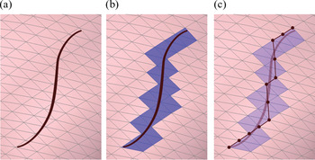
Preparation of the source curve and associated anchor vertices. (a) The user draws the source curve on the surface. (b) The triangles occluded by the source curve are used to identify (c) a path of anchor vertices at which the geometric constraints are imposed. [A color version of this figure can be viewed online at http://journals.cambridge.org/aie]

5.2.1. Sketch-based surface editing
The user starts editing the surface by first drawing a source curve over the surface that acts as a deformation handle that can stretch and twist the surface. The user then draws the target curve from any convenient viewpoint. The surface is deformed with LSE such that the projection of the source curve matches the target curve in that particular view.
The geometric constraints in LSE are given in terms of the positions of vertices, thus the source curve has to be represented as a chain of vertices on the surface. Figure 9 illustrates the process of determining this chain of vertices from the source curve. We start by identifying a set of triangles that are occluded by the source curve (Fig. 9b). For each end of the source curve, we pick the closest vertex to the end point from the occluded set of triangles. We then pick the shortest path between these two end vertices such that each triangle in the set has at least one vertex on the path (Fig. 9c). These vertices, which we call the anchor vertices, are subsequently used to impose the geometric constraints on LSE.
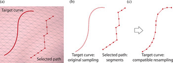
The spacing between the anchor vertices appear shorter or longer on the viewing plane depending on the local orientation of the surface, the vertices' original spacing on the surface, and the view projection. For a meaningful deformation, the anchor vertices should be constrained on the proper positions of the target curve. For this, we first calculate the normalized chord length at the anchor vertices on the viewing plane (Fig. 10b). We then resample the target curve with the same number of points which share the same normalized chord length values as the anchor vertices on the viewing plane (Fig. 10c).
The compatible resampling of the target curve. (a) The user-drawn target curve and the anchor vertices. (b) The original sampling of the target curve is discarded and replaced with the original sampling of the anchor vertices in the particular viewing plane (c) to determine the positions of the anchor vertices for the geometric constraints. [A color version of this figure can be viewed online at http://journals.cambridge.org/aie]

The new sampled points on the target curve are assigned to be the target locations of the anchor vertices on the viewing plane. To augment these geometric constraints into LSE (Equation 8) we write the constraint equations on the viewing plane using the view transformation as follows:
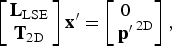
where LLSE is the LSE matrix, T2D is the view transformation that converts three-dimensional positions of the anchor vertices into tw-dimensional positions on the viewing plane, p′2D is the two-dimensional positions of the target vertices on the viewing plane. The solution to the above equation is the set of final locations that satisfy the constraints on the viewing plane while minimizing the deformations in a least squares sense.
5.2.2. Propagation of deformation across scales
Once the deformed surface is calculated, we rectify the residuals of the Laplacian coordinates that were omitted in the multiscale representation. For this, we calculate a transformation that reorients and scales the local frame at a vertex from the original coordinates to the deformed coordinates. For each vertex, this transformation is calculated by solving the following problem:
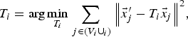
where V i are the indices of the neighboring vertices in the one-ring neighborhood of the ith vertex. We then separate the rotation transformation from this joint transformation using the polar decomposition method given in Shoemake and Duff (Reference Shoemake and Duff1992) as

where R i and S i are the rotation and scale/shear transformations respectively. The extracted rotation transformation is applied to the residuals of the Laplacian coordinates to adjust them according to the modified local frames as
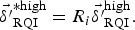
This in turn reassures the compatibility of the residuals in the multiscale representation, which is especially critical in cases where large surface deformations occur.
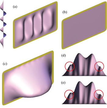
Figure 11 illustrates the difference arising due to the orientation rectification. The interior region of the wavy surface shown in Figure 11a is selected as the ROI and the base surface (Fig. 11b) is calculated. The resulting shapes after adding the residual Laplacian coordinates on to the deformed base shape (Fig. 11c) are shown with and without the orientation rectification in Figure 11d and 11e, respectively. Note that the waves toward the edges of the surface are compressed without the rectification, whereas the same waves are reconstructed without compressions with the rectification.
(a) The interior region of the wavy surface with the region of interest. In the online-only version, yellow denotes the anchored faces. (b) The base shape is (c) deformed. The resulting shapes after adding the residual Laplacian coordinates onto the deformed base shape (d) without and (e) with orientation rectification. Note the resulting compressed regions in (d) (marked in red circles online) without orientation rectification. [A color version of this figure can be viewed online at http://journals.cambridge.org/aie]

6. RESULTS AND DISCUSSION
We implemented the proposed method in C++ using the Qt Framework as the front end. The user interacts with the system via a graphics tablet. For the matrix algebra and least squares problems, the processor optimized Intel MKL routines are used. OpenGL is used to visualize models and to support operations involving the view and perspective projections. Our experiments have shown that the computationally most expensive step of the method is the eigen analysis of the discrete Laplacian matrix. For a ROI of 850 vertices, the calculation of 50, 250, and 500 modes takes 0.15, 2.8, and 8.3 s, respectively, on a dual core notebook with 3 GB of RAM. The second computationally most expensive step is the preparation of the LSE matrix. It takes around 0.35 s for a model with 20,000 vertices. The other calculations happen at interactive speeds. When compared with prior methods, the computational cost of our sketch-based editing steps is similar to the previous methods using LSE. However, prior to editing, the eigenanalysis that is strictly required for the multiscale decomposition of the model is carried out. This may cause a few seconds of delay (as listed above) right after the selection of the ROI depending on the number of vertices in the ROI.
We demonstrate the capabilities of the proposed method with three design examples. The first example illustrates shape exploration on a vase model with features and surface details using the base shape only. Specifically, the model shown in Figure 12a contains surface features formed by cavities and bumps. The user selects a part of the model using the lasso tool to demarcate the ROI. After the selection of the ROI and the fixed regions (denoted with bright lavender color and yellow, respectively) the base shape is calculated as shown in Figure 12c. The user then draws a stroke to define a source curve as shown in Figure 12d. The identified source curve (Fig. 12e) is then modified with a target curve that the user draws from a selected viewpoint (Fig. 12f). The previously decomposed surface details are then added back on to the deformed base shape after the residual Laplacian directions are rectified. As a result (Fig. 12i), large-scale deformations are applied to the surfaces with smaller scale features. The second example also illustrates shape exploration on a gas tank model with features and surface details using the base shape. Specifically, the model shown in Figure 13a,b has a cap at the top and grooves on the side. After the selection of the ROI and the fixed regions (denoted online with bright lavender and yellow, respectively) the base shape is calculated as shown in Figure 13c. The source curve shown in Figure 13d is then modified with a target curve shown in Figure 13e. The separated surface details are then added back on to the deformed base shape. Similar to the first example, large-scale deformations are applied to the surface while preserving small-scale features.
(a) A vase model. (b) The user selection of the region of interest using the lasso tool. (c) The resulting base surface from two different angles. (d) The user draws a source stroke on the region of interest and (e) the associated series of vertices that lay underneath the stroke are selected. (f) The user then draws the final shape of the source stroke from a user-selected viewpoint. (g) The surface is deformed such that the source stroke matches the target stroke from this particular viewpoint. (h) The previously separated details are put back onto the deformed surface, (i) resulting in the final shape shown from different views. [A color version of this figure can be viewed online at http://journals.cambridge.org/aie]

(a,b) A gas tank model with features and surface details is modified. (c) The base model is deformed by (d) the attached anchor curve and (e) the associated target curve. (f) The resulting surface is recombined with the separated features (g,h) to form the final shape. [A color version of this figure can be viewed online at http://journals.cambridge.org/aie]

Applying deformations to feature-free representations helps circumvent complications that can occur in a sketch-based system. On a model where the original features are present, the source curve inevitably captures the small-scale features and maps them to the target curve. As it is difficult for the user to precisely recreate the deformed features using a sketch-based interface, these features are typically undesirably distorted when the conventional LSE is used. In contrast, the multiscale representation allows the designer to work at a coarser representation, thereby enabling the use of causally drawn curves for geometric editing at a congruent level of granularity.
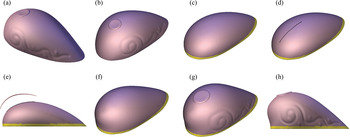
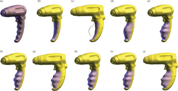
The third example demonstrates the multiscale representation and surface editing capabilities of the proposed method on a hand-held drill example shown in Figure 14a. The handle of the tool features grooves for finger placement while each of them has smaller scale bumps. First, the grooves on the handle are modified on the base shape while all the grooves and bumps are separated as small and medium scale features (Fig. 14b). The surface is then deformed with the attached anchor curve and the associated target curve shown in Figure 14c. The resulting surface (Fig. 14d) is recombined with the separated features (Fig. 14e). Second, a modification is made on the grooves after separating the small scale bumps as shown in Figure 14f–g. To do so, first 75 mode shapes are used to represent the ROI. The small-scale bumps are then placed back on to the grooves hence reproducing the initially suppressed details. The modifications applied at two different levels of details results in two distinct set of deformations. With this approach, the user can impart modifications at different levels of detail without being concerned with feature preservation.
(a) A hand-held drill model with a handle having grooves and bumps is modified at two different scales. (b) The base shape is modified with the attached anchor curve and (c) the associated target curve. (d) The deformed base shape is (e) recombined with the separated details. (f) The shape at a medium level of detail (g,h) is modified and (f,g) recombined with the separated features to form the final shape. [A color version of this figure can be viewed online at http://journals.cambridge.org/aie]

7. CONCLUSIONS
In this work, we present a sketch-based design exploration method that works from existing geometries with free-form surfaces. We propose a multiscale representation of the geometry accompanied with a sketch-based multiscale surface editing approach. One key contribution of our method is that it provides a means to visualize and edit geometries at a chosen level of geometric detail, while automatically transferring the deformations across different levels of detail. With our approach, designers can interact with existing models in a way similar to they work using sketches. We demonstrated the proposed method on design cases that illustrate the sketch-based design exploration. Our future goals include developing more efficient ways of calculating the multiscale representation as well as other types of sketch-based editing interactions.
Günay Orbay is a PhD candidate in the Department of Mechanical Engineering at Carnegie Mellon University. He has a BS and an MS in mechanical engineering from the Middle East Technical University. Günay's research interests include pen-based user interfaces, intelligent assistance in conceptual design, human–computer interaction, curve and surface design, computational aesthetics, and styling.
Mehmet Ersin Yümer is a PhD candidate in the Department of Mechanical Engineering at Carnegie Mellon University. He has a BS and an MS in mechanical engineering from the Middle East Technical University. Mehmet's research interests include augmented/virtual reality interfaces, human–computer interaction, curve and surface design, surface reconstruction, computational aesthetics, and styling.
Levent Burak Kara is an Associate Professor in the Department of Mechanical Engineering at Carnegie Mellon University. He has a BS in mechanical engineering from the Middle East Technical University and an MS and PhD in mechanical engineering from Carnegie Mellon University. Dr Kara's research interests include computational design, geometric modeling, sketch-based interfaces, human–computer interaction, and artificial intelligence.