NOMENCLATURE
- ARI
aileron to rudder interconnect
 $C{a_b} = \frac{{\partial Ca}}{{\partial b}}$
partial derivative of parameter Ca with respect to parameter b in 1/radian
- ${\text{Ix}}, {\text{Iy}}, {\text{Iz}}$
moment of inertia along X-axis, Y-axis and Z-axis, respectively, in kg m2
- ${\text{Ixy}}, {\text{Iyz}}, {\text{Ixz}}$
moment of inertia in XY-plane, YZ-plane and XZ-plane, respectively, in kg m2
- $K_{ARI}$
aileron to rudder interconnect gain
- $K_{p}, K_{\beta}$
roll rate feedback gain and side-slip feedback gain, respectively
- ${K_{{B_w}}}$
wash-out side-slip rate feedback gain
- $L_{\beta}, L_{\delta a}, L_{\delta r}$
roll angular acceleration per unit β, δa and δr, respectively, in °/s2/°
- $L_{p}, L_{r}$
roll angular acceleration per unit p and r, respectively, in 1/s
- ${\text{loe}}, {\text{lie}}$
port-side left outboard and inboard elevon position, respectively, in °.
- $N_\beta, N_{\delta a}, N_{\delta r}$
yaw angular acceleration per unit β, δa and δr, respectively, in °/s2/°
- $N_p, N_r$
yaw angular acceleration per unit p and r, respectively, in 1/s
- $N_{y}$
lateral acceleration in g
- $\dot p, \dot r$
roll acceleration and yaw acceleration, respectively, in °/s2
- $q, p, r$
body-fixed axis pitch rate, roll rate and yaw rate, respectively, in °/s
- ${\text{roe}}, {\text{rie}}$
starboard-side right outboard and inboard elevon position, respectively, in °
- ${\text{rud}}$
rudder surface position in °
- $V_{T}$
true airspeed in m/s
- $Y_{p}, Y_{r}$
lateral acceleration per unit p and r, respectively, in m/s/°
- $Y_\beta, Y_{\delta a}, Y_{\delta r}$
lateral acceleration per unit β, δa and δr, respectively, in m/s2/°
- α
angle-of-attack (AoA) in °
- β
angle of side slip (AoSS) or beta in °
- $\delta a, \delta r$
aileron and rudder surface deflection, respectively, in °
- $\phi $
roll angle in °
- ${{\dot{\beta}}}$
side-slip rate in °/s
- $\dot \phi $
rate of roll angle or bank angle in °/s
- α0
initial angle-of-attack in °
- τw
wash-out filter time constant in s


1.0 INTRODUCTION
Over the last few decades, a great deal of attention has been paid to the investigation of interconnected, multivariable control systems(Reference Jafarov and Tasaltin1). The lateral directional control of aircraft(Reference Balas, Packard, Renfrow, Mullaney and M'closkey2,Reference Fialho, Balas, Packard, Renfrow and Mullaney3) is an interesting Multi-Input Multi-Output (MIMO) flight control problem because of the significant dynamic coupling between the axes. Basic classical interconnected multivariable control systems have been developed for the F-16 and passenger jet aircraft(Reference McLean4–Reference Roskam7). Nevertheless, open literature is bereft of a systematic procedure to design such interconnected control systems.
The primary design objective of the lateral directional control law is to provide a crisp and predictable roll angle response for the aircraft while minimising the side slip. A control system with roll rate, yaw rate and angle of sideslip feedback to the aileron and rudder can be designed to meet the static and dynamic stability requirements. However, due to the significant cross-axis coupling, the aileron input will cause side slip to build up and result in a contaminated roll response due to the Dutch roll mode. Different methods(Reference Blakelock6) for achieving coordinated turns are described by Blakelock. The dynamic coupling cannot be neglected, especially at high angles of attack and high rotational rates. Multiple combinations of aerodynamic deficiencies at high angles of attack can cause motions such as wing drop, wing rock and nose slice, causing the aircraft to depart from controlled flight in the lateral directional mode.
ARI gain is designed to decouple the Dutch roll mode from the roll rate response to the aileron input while minimising the side slip(Reference Ellis8). It is intended to generate the component of the yaw rate necessary to achieve roll in the stability axis to ensure lateral directional stability. This reduction in the adverse yaw and oscillatory response (especially at high angles of attack) due to aileron deflection and the improved control of the side slip is possible by using an interconnecting gain design(Reference Barnes and Nicholas9). NASA has conducted specific flight tests to evaluate aileron–rudder interconnects on the F-14A airplane in the landing configuration(Reference Kelley and Enevoldson10). The standard F-14 flight control systems with two ARI configurations were tested. The results of the flight test showed a remarkable improvement in the handling quality when using ARI. Side slip due to adverse yaw was considerably reduced, the handling quality was improved, and the airplane turn rate was more responsive to pilot lateral control inputs when using ARI. The pilot commented that the ARI systems were superior to the standard control system in terms of the capability to make lateral offset corrections and heading changes on final approach(Reference Kelley and Enevoldson10). The flight manual of the F16-A/B(11) highlights that, after damage to the horizontal tail or wing, roll stick activity is required to bring the aircraft to wings level. This task is challenging but not unmanageable. After this type of damage, reconfiguration of the ARI will certainly improve aircraft handing, especially for landing tasks.
Feedforward control does not affect aircraft stability but rather provides a direct solution to the control problem by measuring the disturbances and compensating the controlled variable before it deviates from the set point. The feedback control system is typically designed to handle specified levels of uncertainty, while the feedforward control system remains susceptible to uncertainty. In the lateral directional control system, feedback of the roll rate, yaw rate and angle of side slip addresses such uncertainty in order to meet stringent MIL requirements on gain and phase margin (i.e. 6dB and 35°, which can account for up to 50% of plant variation). Thus, the flight control system will naturally be able to handle some fault scenarios without requiring flight control law reconfiguration. However, decoupling the lateral and directional dynamics, e.g., using the ARI scheme, employs a feedforward gain that is susceptible to plant uncertainty. To the best of the authors’ knowledge, current industry practice regarding ARI gain design uses an iterative procedure(Reference Stevens and Lewis5). Primarily, the gain design is carried out using trim algorithms, then finer refinements are made based on nonlinear simulations. However, such methods are not useful to handle real-time fault scenarios and are also not practically applicable for online ARI reconfiguration.
This paper describes a systematic non-iterative procedure for ARI gain design that could be useful for real-time ARI reconfiguration. The approach is demonstrated for an aileron control surface damage scenario on a typical fighter aircraft. A single-engine fighter aircraft having two pairs of elevons (elevator and aileron) and a single rudder control surface is considered for this investigation. The proposed method requires real-time estimation of transfer function coefficients.
The remainder of this paper is organised as follows: The plant model, design specifications and classical control law structure with the conventional ARI design are explained in Section II. In Section III, two methods for ARI gain design are proposed. Section IV presents the simulation results, demonstrating the benefit of online ARI gain reconfiguration when a specific fault case is triggered. The final section provides concluding remarks, highlighting the importance of determining the ARI gain in real time, which represents the main contribution of this paper.
2.0 AIRCRAFT MODEL AND CONVENTIONAL ARI DESIGN
The non-linear rigid-body equations of motion(Reference Stevens and Lewis5–Reference Roskam7) form the basis for simulation and controller design. The aircraft dynamics is linearised by using a small perturbation technique, and a lateral/directional linear model, suitable for control law design, is obtained with β, p, r and  $\phi $ as the states, δa and δr as the inputs, and
 $\phi $, β, p, r and Ny as observations. By ignoring the
 $\dot \phi $ equation and the dependence on
 $\phi $, the lateral and directional model for the aircraft in state space is given by Equation (1). The spiral mode, being a low-frequency mode because of its long time constant, is not significant from a handling quality point of view and is thus excluded from the state-space model. Hence, a third-order simplified state variable model is considered with the state vector defined as x = [p, r, β] and u = [δa, δr].
 $\dot x = A\;x + B\;u$, where A and B are as defined in Equation (1)
 \begin{align}\left[ \begin{array}{c}
{\dot p}\\[3pt]
{\dot r}\\[3pt]
{\dot \beta}
\end{array} \right]
= \left[
\begin{array}{c@{\quad}c@{\quad}c}
{{L_p}} & {{L_r}} & {{L_\beta }}\\[3pt]
{{N_p}} & {{N_r}} & {{N_\beta }}\\[3pt]
{{Y^{\prime}_p}} & {{Y^{\prime}_r}} & {{Y^{\prime}_\beta}}\end{array} \right]
\left[
{\begin{array}{c}
p\\[3pt]
r\\[3pt]
\beta \end{array}}
\right] +
\left[
{\begin{array}{c@{\quad}c}
{{L_{\delta a}}} & {{L_{\delta r}}}\\[3pt]
{{N_{\delta a}}} & {{N_{\delta r}}}\\[3pt]
{{Y_{\delta a}}} & {{Y_{\delta r}}}\end{array}}
\right]
\left[
\begin{array}{c}
{\delta a}\\[3pt]
{\delta r}
\end{array} \right]
\end{align}
where  ${Y^{\prime}_p} = ({Y_p}/{V_T}) + sin{\alpha _0}$,
 ${Y^{\prime}_r} = ({Y_r}/{V_T}) - \cos {\alpha _0}$,
 ${Y^{\prime}_\beta} = ({Y_\beta }/{V_T})$.
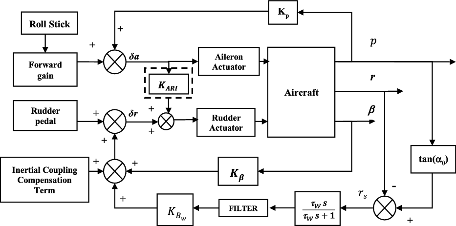
Consider the nominal lateral/directional control schematic(Reference Chetty and Deodhare12,Reference Srinathkumar13) shown in Fig. 1. The main objective of the lateral directional control law for a fighter aircraft is to augment the directional stability and Dutch roll damping (which could be quite poor) and to improve the handling quality (e.g. a crisp roll rate response, good disturbance rejection and good turn coordination). In response to roll stick input, the aircraft at high angles of attack rolls about the velocity vector to suppress the kinematic coupling between the AoA and the side-slip angle. The stability axis angular rates  ${{\rm{p}}_{\rm{s}}} = {\rm{p\;}}$ and
 ${{\rm{r}}_{\rm{s}}} = {\rm{r - ptan}}\alpha {\rm{\;}}$ are used instead of the body axis angular rates for feedback. Furthermore, the inertial coupling compensation term
 $\left( {{{\Delta \dot r}} = \left( {\frac{{{{\rm{I}}_{\rm{y}}}{\rm{ - }}{{\rm{I}}_{\rm{x}}}}}{{{{\rm{I}}_{\rm{z}}}}}} \right){\rm{pr}}} \right)$ is also added to the feedback terms of the directional axis. The lateral/directional control law(14,15) is designed to meet the specifications given in the MIL requirements documents.
Lateral directional feedback control law schematic.

Note that  ${K_{ARI^\circ }}$ is replaced by
 ${G_{ARI^\circ }}$ obtained from method 1 for the simulations used.
The transfer functions for the roll rate (p) and side slip (β) can be derived from Equation (1), and expressed as
 ${G_{p\delta a}}(s) = \frac{{p(s)}}{{\delta a}}$,
 ${G_{p\delta r}}(s) = \frac{{p(s)}}{{\delta r}}$,
 ${G_{\beta \delta r}}(s) = \frac{{\beta (s)}}{{\delta r}}$, as given in Equations (2) and (3).
 \begin{equation}p(s) = {G_{p\delta a}}(s )\delta a( s ) + \;{G_{p\delta r}}( s )\delta r( s )\end{equation}
 \begin{equation}\beta ( s ) = {G_{\beta \delta a}}( s )\delta a( s ) + \;{G_{\beta \delta r}}( s )\delta r( s )\end{equation}
The ARI gain ( ${K_{ARI^\circ }}$) is synthesised, after the primary feedback loops have been appropriately designed, to decouple the Dutch roll mode from the roll rate response to the aileron input. This (
 ${K_{ARI^\circ }}$) gain is conventionally implemented as shown in Equation (4)
 \begin{equation}\delta r = {K_{ARI}}\delta a\end{equation}
With the ARI gain as given in Equation (4), Equation (2) can be rewritten as
 \begin{equation}p(s) = \left( {{G_{p\delta a}}(s) + {K_{ARI}}{G_{p\delta r}}(s)} \right)\delta a(s)\end{equation}
Thus, the effect of increasing the ARI gain is to move the closed-loop  $\left({G_{p\delta a}}(s) + \right.$
 $\left. {K_{ARI}}{G_{p\delta r}}(s)\right)$ zeros, as given in Equation (5), towards the open-loop (
 ${{G_{p\delta r}}}$) poles. The gain is then selected to place a zero close to the augmented Dutch roll poles, to achieve approximate pole-zero cancellation.
Example 1: Consider the linear model for a generic fighter at a flight condition of 0.4 Mach number and 1.0km altitude (henceforth 0.4M, 1.0km).
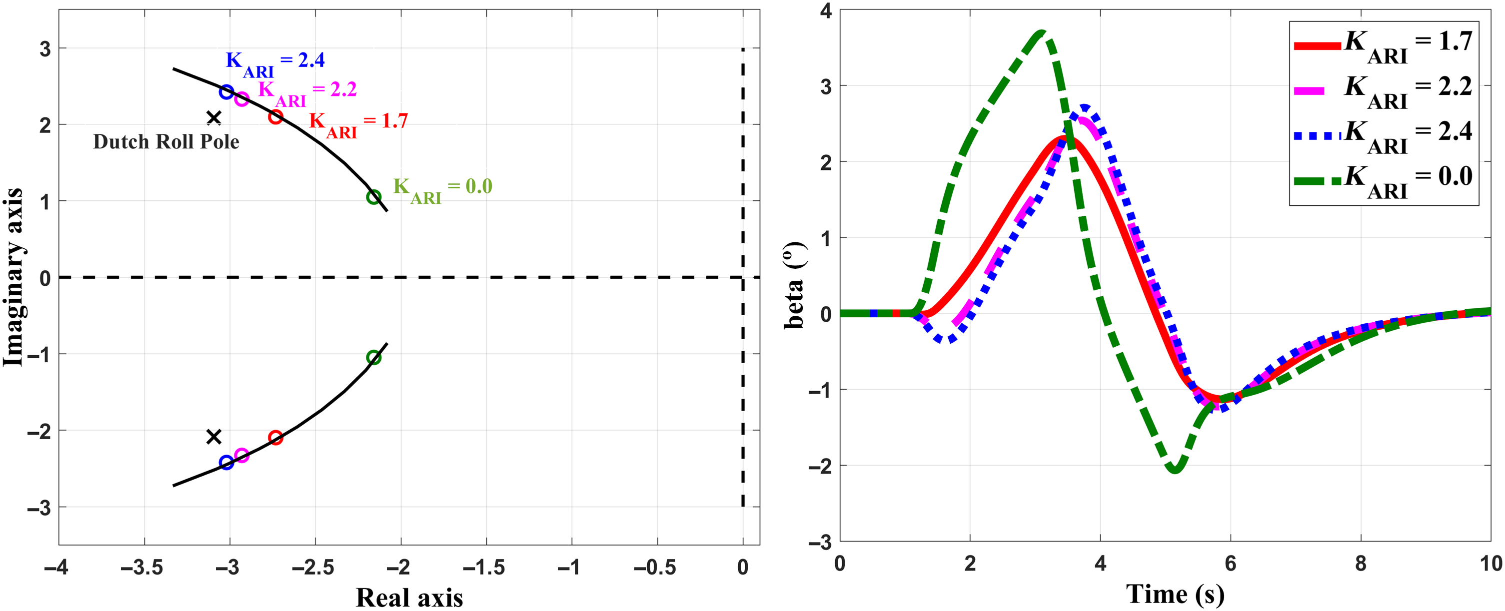
Figure 2 show the locus of  ${{{\rm{G}}_{{\rm{p\delta a}}}}}$ zero with different
 ${{{\rm{K}}_{{\rm{ARI}}}}}$ gains and augmented Dutch roll pole. The side-slip (beta) time response for different
 ${{{\rm{K}}_{{\rm{ARI}}}}}$ gains is also plotted in Fig. 2 with roll stick doublet (at 1 s) input. Note from Fig. 2 that the pole-zero distance is lower for ARI gains of approximately 2.2 to 2.4. However, the ARI gain that generates the minimum side slip, as seen from the time response plots, is seen to be
 ${{{\rm{K}}_{{\rm{ARI}}}}}$ = 1.7. This example reveals the issues with the traditional design procedure.
Plot showing the location of the Dutch roll pole and zero of  ${G_{p\delta a}}(s) + {K_{ARI}}\;{G_{p\delta r}}( {\rm{s}} )$ to study the sensitivity of ARI gain for 0.4M, 1km and also the plot of the angle of side-slip response with roll stick input for different ARI gains.

ARI gain selection cannot be automated if it is based on the placement of the root location close to the Dutch roll pole, or based on the Hankel norm(Reference Jee, Sharma, Rao, Zachariah, Brinda, Lalithambika, Dhekane, Deodhare and Chetty16), or verifying it with closed-loop time response simulations or HQ assessment using real-time simulators. The methods currently used for  ${{K_{ARI}}}$ design are, therefore, based on an iterative process. For online reconfiguration, a non-iterative method for
 ${{K_{ARI}}}$ gain design is essential.
3.0 PROPOSED METHODS OF ARI DESIGN
In this section, two alternative methods for ARI design are proposed. The basic requirement is to nullify the side slip caused by an aileron input by applying an appropriate rudder input. The side-slip response, as derived in Equation (3), is equated to zero to nullify the side slip, as shown below:
 \begin{equation}\beta (s) = {{\rm{G}}_{\beta {\rm{\delta a}}}}(s)\delta a(s) + {{\rm{G}}_{\beta {\rm{\delta a}}}}(s)\delta r(s) = 0\end{equation}
The required rudder  $\delta r$ can be derived from Equation (6) as
 \begin{equation}\delta r = - \frac{{{G_{\beta \delta a}}(s)}}{{{G_{\beta \delta r}}(s)}}\delta a = {G_{ARI}}(s)\delta a\end{equation}
where  ${{\rm{G}}_{{\rm{ARI}}}}\left( {\rm{s}} \right)$ is the ARI transfer function. Note that Equation (3), used in the above derivation, is the open-loop transfer function. Hence, it does not consider the feedback loops discussed in Section II, as shown in Fig. 1. It can be shown that the above derivation of
 ${G_{ARI}}(s)$ holds in the closed-loop case also.
A. Proposed method 1 for the ARI design
In this method, the ARI is directly taken as the transfer function, as in Equation (7) above, instead of the static  ${K_{ARI}}$ gain.
 ${G_{ARI}}(s)$ can be derived analytically from the third-order lateral directional model given in Equation (1), and is given in Equation (8). For real-time implementation of the ARI transfer function, real-time estimation of the lateral and directional parameters, as listed in Equation (8), is required. All the elements or parameters required to calculate
 ${G_{ARI}}(s)$ can be obtained using real-time estimation of the parameters (and possibly from aero database tables, which can also be carried onboard to make parameter estimation more reliable).
 \begin{equation}{G_{ARI}}(s) = - \frac{{\frac{{\beta (s)}}{{\delta a(s)}}}}{{\frac{{\beta (s)}}{{\delta r(s)}}}} = - \frac{{{G_{\beta \delta a}}(s)}}{{{G_{\beta \delta r}}(s)}} = \frac{{A1\,{s^2} + A2\,s + A3}}{{B1\,{s^2} + B2\,s + B3}}\end{equation}
Where  $A1 = {Y_{\delta a}}$,
 $B1 = - {Y_{\delta r}}$,
 $A2 = - ( {{Y_{\delta a}}{L_p} + {Y_{\delta a}}{N_r} - {L_{\delta a}}Y^{\prime}_p - {N_{\delta a}}{Y^{\prime}_r}} )$
 $B2 = ( {{Y_{\delta r}}{L_p} + {Y_{\delta r}}{N_r} - {L_{\delta r}}Y^{\prime}_p - {N_{\delta r}}{Y^{\prime}_r}} )$
 $A3 = - {Y_{\delta a}}( {{L_r}{N_p} - {L_p}{N_r}} ) + {L_{\delta a}}( {{N_p}Y^{\prime}_r - {N_r}{Y^{\prime}_p}} ) + {N_{\delta a}}( {{L_r}Y^{\prime}_p - {L_p}{Y^{\prime}_r}} )$
 $B3 = {Y_{\delta r}}( {{L_r}{N_p} - {L_p}{N_r}} ) - {L_{\delta r}}( {{N_p}Y^{\prime}_r - {N_r}{Y^{\prime}_p}} ) - {N_{\delta r}}( {{L_r}Y^{\prime}_p - {L_p}{Y^{\prime}_r}} )$
B. Proposed method 2 for the ARI design
Traditionally, ARI is taken to be a flight-condition scheduled gain, instead of a transfer function as obtained above. As seen from Fig. 2, the primary effect of the  ${K_{ARI}}$ gain is visible in the transient response when a roll manoeuvre is initiated.
 ${K_{ARI}}$ is a static interconnect gain which plays an important role in shaping the transient response. The roll mode is typically the fastest among the roll, spiral and Dutch roll modes. Therefore, the transient response is primarily influenced by the roll mode, which is defined by the roll damping (
 ${L_p}$). The Dutch roll mode and the spiral mode are relatively long-term responses. Hence, intuitively, the magnitude of
 ${G_{ARI}}(s)$ at the roll mode (
 ${L_p}$) frequency can be considered to be the
 ${K_{ARI}}$ gain. To confirm this, six degree of freedom simulations were carried out for a generic fighter aircraft in various flight conditions. It was found that
 ${K_{ARI}}$ computed as the magnitude of
 ${G_{ARI}}(s)$ at the roll damping (
 ${L_p}$) frequency gives the minimum side slip, and therefore, the same is proposed in this paper. The sign of
 ${K_{ARI}}$ is selected based on the sign of the real part of
 ${G_{ARI}}(s)$, as shown in Equation (9).
 \begin{equation}{K_{ARI}} = sign\left( {real\left( {{G_{ARI}}\left(\, {j{L_p}} \right)} \right)} \right){\rm{*}}\left| {{G_{ARI}}\left(\, {j{L_p}} \right)} \right|\end{equation}
The proposed method for computing  ${K_{ARI}}$ is simple and non-iterative, and can be used for gain reconfiguration in near real time in case of faults. It is computationally more efficient than method 1, as it does not require a transfer function computation in each control cycle.
C. Comparison of the nonlinear simulation responses with the proposed methods
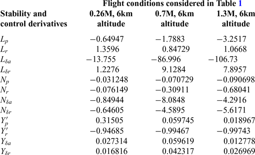
Nonlinear 6DoF simulation is carried out with all 12 states(Reference Stevens and Lewis5) using flight-validated simulation software. The step size used in the simulation is 0.0125 s, and simulations were carried out for a fixed mass (~9000kg), moments of inertia (Iyy = 66,558.9, Ixx = 14,087.9, Izz = 77,875.2, Ixy = 162.5, Iyz = 32.5, Izx = 2490.5), and centre of gravity (34% of the mean aerodynamic chord). In this section, simulation results for a typical fighter aircraft are presented for the three flight conditions of wings level trim (1g) as listed in Table 1. The stability and control derivatives of the three flight conditions considered are presented in Table 2.
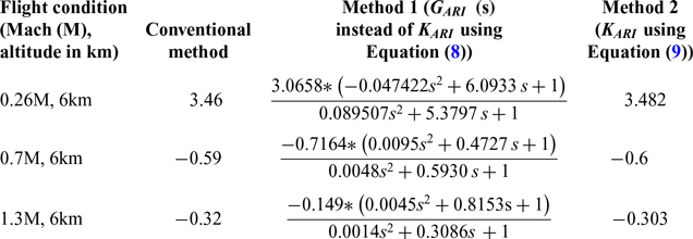
The ARI obtained using the proposed methods is presented in Table 1 for these flight conditions. Note that the ARI gain values as obtained using the conventional method and method 2 are in fairly good agreement.
ARI gains with three proposed methods

Stability and control derivatives for flight conditions considered in Table 1

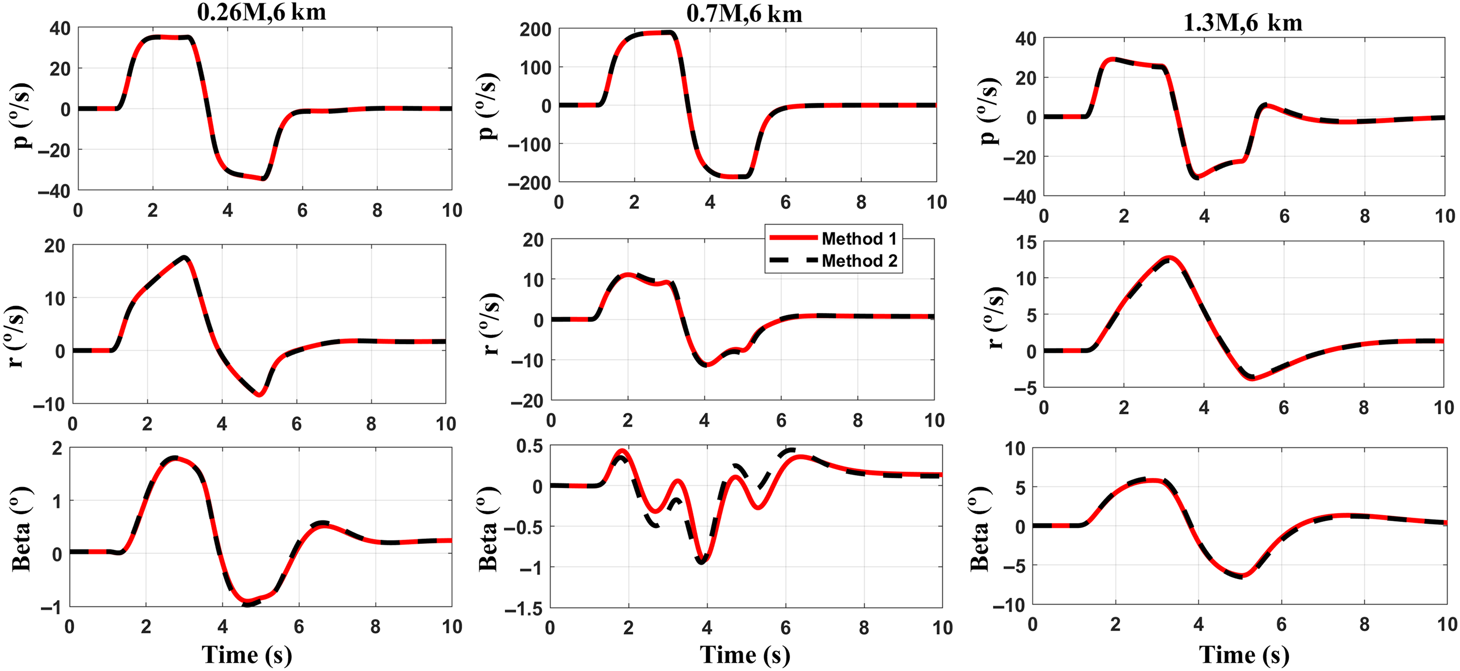
The nonlinear simulation response to roll stick doublet input at three flight conditions, for different values of ARI (i.e.,  ${{G_{ARI}}}$ using method 1 and
 ${K_{ARI}}$ using method 2), is plotted in Fig. 3. Note that the time response is similar. To assess the computational complexity, C codes are generated for both methods and compared using the default configuration settings for a generic real-time target using Simulink MATLAB software. It is observed that the size of the code with
 ${K_{ARI}}$ is smaller than that with
 ${{G_{ARI}}}$, which can lead to a smaller footprint of embedded code. Also, the output function generated by
 ${{K_{ARI}}}$ is less than the output function generated by
 ${{G_{ARI}}}$. Hence, the single gain (
 ${{K_{ARI}}}$) evaluation is computationally much more efficient than the transfer function (
 ${{G_{ARI}}}$) evaluation, and thus particularly useful for real-time reconfiguration.
Comparison of nonlinear simulation responses at 6km altitude with  ${K_{ARI}}$ and
 ${G_{ARI}}$.

4.0 RECONFIGURATION OF ${{\textbf{K}}_{{\textbf{ARI}}}}$ GAIN FOR LEFT OUTBOARD CONTROL SURFACE DAMAGE SCENARIO

Some fault scenarios, such as total/partial damage to a control surface or a fault due to battle damage or a bird strike, cannot be detected either through hardware or through software redundancy management techniques. In such cases, manoeuvring by the pilot with full stick input demand could lead to departure of the aircraft, if the fault is not identified and the control law is not reconfigured in real time. To illustrate this, the case of left outboard control surface damage is considered in this paper. This is modelled as a 90% effectiveness drop, i.e., a reduction in the surface effectiveness in the aero database and simulation using the flight-validated software. For simplicity, the reduction in control effectiveness is assumed to be linear. Further work needs to be carried out based on computational fluid dynamics studies to model the exact relationship.
In this example, the value of the left elevon outboard surface (port side), used for computing the force and moment coefficients from aero database tables, is set to 10% of its value (i.e., a 90% reduction). The rolling moment coefficient(Reference Roskam7), which is modelled for the left control surface damage, is shown by Equation (10).
 \begin{align}{{\rm{C}}_1} & = {\rm{C}_{1\beta }}\left( \beta \right) + {\rm{C}_{1\rm{p}}}\left( {\rm{Mach}} \right)\frac{\rm{pb}}{{2\rm{v}}} + {\rm{C}_{1\rm{r}}}\left( {\rm{Mach}} \right)\frac{\rm{rb}}{{2\rm{v}}} + {\rm{C}_{1\delta \rm{r}}}\left( {\alpha,\rm{Mach},\rm{RUD}} \right)\nonumber\\
& \quad + {\rm{C}_{1\delta \rm{a}}}\left( {\alpha,\rm{Mach},\rm{LOE} * 0.1} \right) + {\rm{C}_{1\delta \rm{a}}}\left( {\alpha,\rm{Mach},\rm{LIE}} \right) + {\rm{C}_{1\delta \rm{a}}}\left( {\alpha,\rm{Mach},\rm{RIE}} \right)\nonumber\\
& \quad + {\rm{C}_{1\delta \rm{a}}}\left( {\alpha,\rm{Mach},\rm{ROE}} \right)\end{align}
where  ${\rm{C}_{1\beta }}$,
 ${\rm{C}_{1\rm{p}}}$,
 ${\rm{C}_{1\rm{r}}}$,
 ${\rm{C}_{1\delta \rm{r}}}$,
 ${\rm{C}_{1\delta \rm{a}}}$ are the rolling moment coefficients of beta, roll rate, yaw rate, rudder and aileron, respectively. In the aero database tables, these coefficients are defined as a function of Mach no. (M, Mach), angle-of-attack (α, AoA), angle of side slip (β, beta), LIE, LOE, RIE and ROE (left and right inboard and outboard surface values) and RUD (rudder surface value). The coefficient
 ${{\rm{C}}_1}$ is the total rolling moment coefficient.
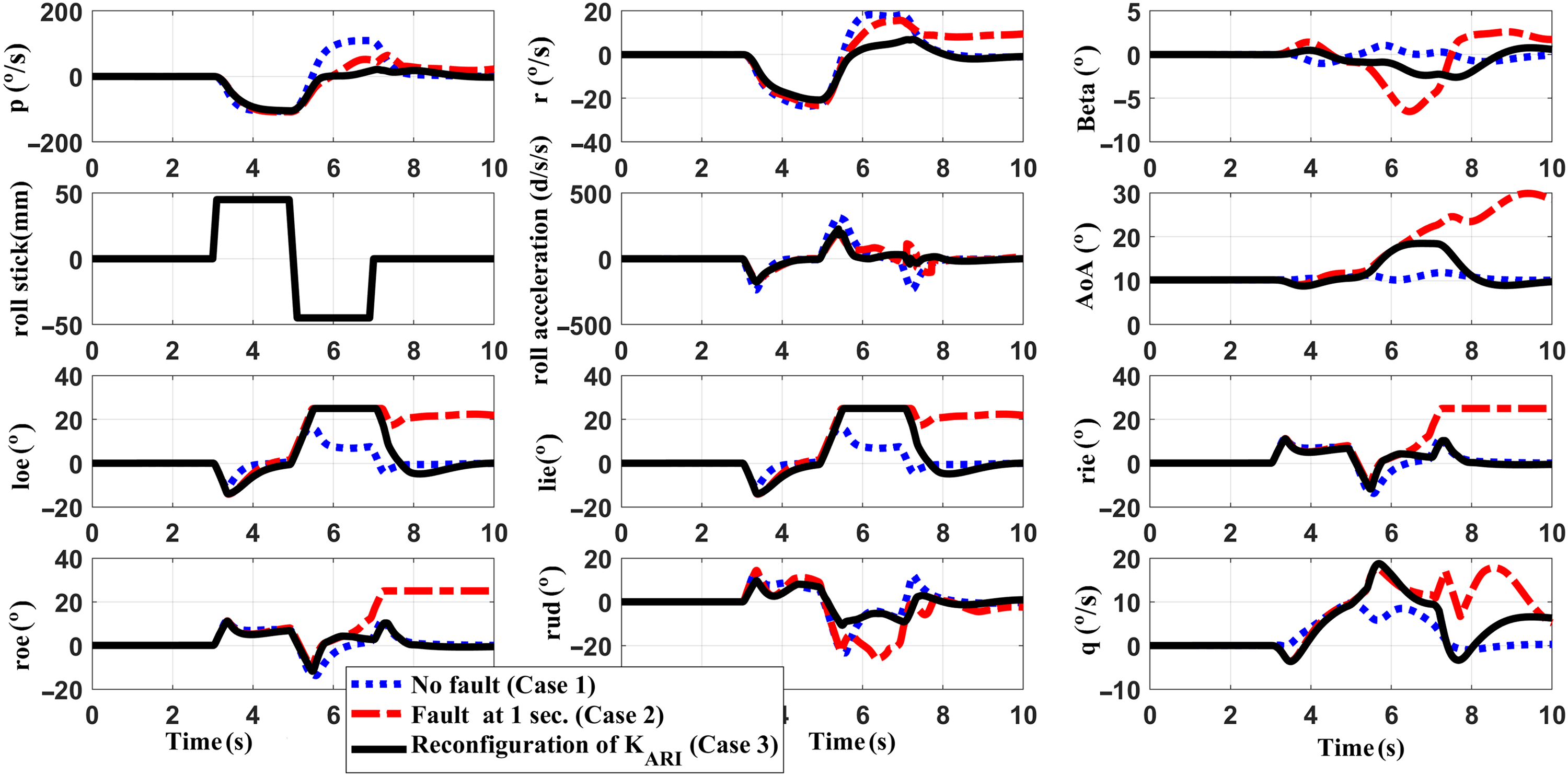
Six-DoF non-linear simulation results are presented for roll stick doublet input at a typical flight condition (0.5 Mach number, 9.6km altitude). The time responses for the following three cases are presented in Fig. 4 to demonstrate the impact of ARI gain reconfiguration in the considered surface damage fault scenario.
ARI reconfiguration using method 2 for reduction of outboard surface effectiveness fault.

Case 1: No-fault condition
This is the desired aircraft response in case of no failures. The pilot applies a full roll-stick doublet at 3 s. Figure 4 shows the responses of roll rate, yaw rate, sideslip, roll acceleration, outboard elevon, inboard elevon positions (loe, roe, lie, rie) and angle-of-attack. These are observed to be adequate for the given roll stick input (rstick in mm).
Case 2: Fault at 1 s, no reconfiguration
In this case, the fault is introduced at 1 s. However, no online fault detection or gain reconfiguration is attempted, and the pilot applies the same roll-stick doublet at 3 s. The responses, e.g., the roll rate, roll acceleration and yaw rate, show abrupt changes. It is observed from Fig. 4 that the AoA reaches about 30° and the side slip builds up to about 7°. All the elevon surfaces are seen to reach their saturation limits. These simulation results clearly show that, if this problem is not addressed, it can lead to control surface saturation and possible aircraft departure.
Case 3: Fault at 1 s, with ARI gain reconfiguration
In this case, the fault is introduced at 1 s and the pilot applies the same roll-stick doublet at 3 s, as in the previous case. However, in this case, online fault detection followed by gain reconfiguration is introduced into the simulation. The fault identification process is explained and presented for the damaged control surface and modelled as a reduction in control effectiveness(Reference Myala, Patel and Singh17). An extended Kalman filter (EKF)-based algorithm(Reference Myala, Patel and Singh17) is used to estimate the control derivatives  ${{\rm{L}}_{{\rm{\delta a}}}}$,
 ${{\rm{N}}_{{\rm{\delta a}}}}$ and
 ${{\rm{Y}}_{{\rm{\delta a}}}}$. The ARI gain calculation in Equation (9) uses these estimated parameters after the occurrence of the fault, while the other stability and control parameters are taken from the aero database tables, which are assumed to be carried onboard. A time delay of 0.35 s was reported for the real-time estimation of lateral and directional parameters(Reference Myala, Patel and Singh17) and ARI gain computation. Therefore, in this example, the
 ${{\rm{K}}_{{\rm{ARI}}}}$ gain is reconfigured using method 2 and updated at 1.35 s. From Fig. 4, it can be observed that, after reconfiguration of
 ${{\rm{K}}_{{\rm{ARI}}}}$, the AoA remains within limits and side slip build-up is reduced to less than 4° (from 7°). Thus, the approach helps in recovery from instability.
5.0 CONCLUSION
The ARI gain plays an important role in decoupling the Dutch roll mode from the roll rate response, while ensuring the velocity vector roll for a commanded aileron input. It is the feedforward correction that is susceptible to plant uncertainty and, therefore, needs fast adaptation/correction whenever a fault occurs. A novel method for ARI gain design is presented herein. It is shown that the computation of the ARI gain design using the magnitude of  ${G_{ARI}}$ at the roll damping (
 ${L_p}$) frequency is non-iterative and more efficient than when using existing, traditional methods. Simulation results for a control surface damage fault scenario are presented. In particular, the proposed approach can be used for near-real-time reconfiguration of the control law whenever a fault occurs. Future work will focus on a rigorous proof for the
 ${K_{ARI}}$ computation described in method 2.
Acknowledgements
The authors would like to acknowledge the anonymous experts/referees for their critical review and constructive suggestions to improve the presentation of this work. The authors are grateful to the Directors of Aeronautical Development Agency and National Aerospace Laboratories for permitting this work to be published.