I. INTRODUCTION
Over the last decades, the development of microelectromechanical systems has made a remarkable progress and the question arises, whether and how the also upcoming bulk metallic glasses (BMGs) with their promising properties can be used in this prospective growing field.Reference Greer and Ma1 Their very high strength and hardness make BMGs well suited for stressed parts in miniature motors or microdrives. Furthermore, several Fe-based glasses exhibit good soft magnetic properties,Reference Roth, Stoica, Degmová, Gaitzsch, Eckert and Schultz2 which also enable functional applications, e.g., as switchable parts in medical components, in micro-relays or as cores in miniature transformers.Reference Inoue and Nishiyama3 But how can these microscaled parts be manufactured under maintenance of the unique amorphous structure? A commonly used method to shape metallic glasses is micromoulding.Reference Kumar, Tang and Schroers4 But this thermomechanical technique is only applicable for glassy alloys, which exhibit a wide undercooled liquid regime at low temperatures and a large viscosity drop. Therefore, it is not employable for high strength Fe-based metallic glasses. Another possible technique is pulsed laser micromachining. It has been already demonstrated for several amorphous alloys,Reference Lin, Lee, Hu, Li and Huang5 but the obtained machining accuracy and the surface finishing are not satisfying yet. Thus, an alternative low cost method is demanded, which operates at moderate temperatures and achieves submicrometer precision.
A novel approach, which meets both criteria, is electrochemical micromachining (ECMM).Reference Landolt, Chauvy and Zinger6 A special ECMM technique using ultrashort voltage pulses and metallic microtools was introduced by Schuster et al.Reference Schuster, Kirchner, Allongue and Ertl7 for microstructuring Cu parts with very high precision. Since then, its applicability has already been well proven for a wide range of crystalline materials, e.g., stainless steel,Reference Cagnon, Kirchner, Kock, Schuster, Ertl, Gmelin and Kück8 Ni,Reference Kock, Kirchner and Schuster9 Ni-based alloysReference Maurer, Mallett, Hudson, Fick, Moffat and Shaw10 or Ti.Reference Sjöström and Su11
To achieve the required precision, this ECMM methodReference Schuster, Kirchner, Allongue and Ertl7 uses a microtool electrode, which is placed at a very close distance to the workpiece surface. When applying ultrashort voltage pulses between the tool and workpiece, the pulse-on voltage charges the workpiece capacity C wp via the electrolyte resistance. As the electrolyte resistance depends on the gap size between the two electrodes, a local sufficient charging of C wp and therewith, a significant anodic dissolution occurs only within a small region between the workpiece and tool electrode. So the method offers the possibility of reproducing the tool electrode shape accurately and in further consequence, it allows the manufacturing of complex microstructures with high aspect ratios.
However, to employ the ECMM for amorphous alloys, two fundamental questions have to be solved: (i) Is the model, which is used for micromachining of electrochemically active (crystalline) materials also applicable for spontaneously passivating (amorphous) alloys? and (ii) Which impact has the single-phase amorphous nature of metallic glasses and their multicomponent composition on the local dissolution process and therefore, on the resulting precision?
For the first time, Maurer et al.Reference Maurer, Mallett, Hudson, Fick, Moffat and Shaw10 showed the successful machining of a passive Ni-based superalloy. To reach a reasonable micropatterning, the exploitation of the transpassive dissolution regime was emphasized. Based on this work, Koza et al.Reference Koza, Sueptitz, Uhlemann, Schultz and Gebert12 demonstrated the machining of a Zr-based BMG in principle, but the obtained structures had still an undesired irregular shape. Further, Sueptitz et al.Reference Sueptitz, Tschulik, Becker, Stoica, Uhlemann, Eckert and Gebert13 presented first machining experiments for selected Fe-based bulk amorphous alloys. It was revealed that sulfuric acid solutions and the use of W microtool electrodes are the appropriate electrochemical cell settings. But satisfying patterning could only be accomplished in methanolic sulfuric acid and not in water-based acid solutions. Concerning the high toxicity and easy flammability of methanolic solutions, this is not the most favored choice for industrial use. Therefore, Sueptitz et al.Reference Sueptitz, Dunne, Tschulik, Uhlemann, Eckert and Gebert14 discussed in the following three possible strategies to impede the formation of disturbing passive layers on the workpiece electrode, which was identified as the key problem of ECMM processing of those Fe-based alloys: (i) the use of an electrolyte free of water, or in water-based acid solutions, (ii) the polarization of the workpiece electrode to the onset of transpassivity or (iii) the introduction of a suitable redox reaction, which controls the microtool cathode process.
The first approach enables the machining of well-defined microsized structures on Fe-based metallic glass surfaces. However, due to the already mentioned immanent risks this option will not be pursued further.Reference Sueptitz, Tschulik, Becker, Stoica, Uhlemann, Eckert and Gebert13 The second way can be implemented by choosing suitable pulse-off voltage or by prepolarizing the workpiece electrode versus an auxiliary electrode. However, in several tests, both conditions led to undesired pitting corrosion of the glassy workpiece surface and enabled no reasonable structuring yet. Finally, the third approach appears to be the most promising and will be explained more detailed in the present work. It will be demonstrated that by using a selected electrolyte composed of a water-based sulfuric acid solution with addition of Fe(III)-based sulfate and by applying ultrashort voltage pulses with amplitudes reaching the transpassive regime, even complex lateral microstructures can be machined with high precision and very smooth surface topography.
II. EXPERIMENTAL
For performing the electrochemical study, the bulk glass-forming Fe65.5Cr4Mo4Ga4P12C5B5.5 alloy has been prepared as cast rods with a diameter of 1.5 mm and a length up to 50 mm.Reference Stoica, Eckert, Roth, Yavari and Schultz15 The amorphous structure of the samples was checked by x-ray diffraction analysis and scanning electron microscopy (SEM). To utilize this BMG as a workpiece electrode in the ECMM process (anodes) 2 mm thick slices of the rod were embedded in epoxy resin, polished with SiC paper (up to grid 4000) and cleaned with distilled water and ethanol before electrochemical testing. For the characterization of the electrochemical behavior of the tool electrode, a W rod (Goodfellow) of 4 mm diameter was embedded in epoxy resin, polished, and cleaned too. The used electrolytes were prepared from deionized water, analytical grade H2SO4 (98%), and analytical grade Fe2(SO4)3.
For characterizing the polarization behavior of the Fe-based glass and the W electrode, potentiodynamic experiments were conducted at room temperature in the machining electrolyte 0.1 M H2SO4 with various Fe2(SO4)3 concentrations using a conventional three electrode cell with a Pt electrode as the counter electrode and a saturated Hg/Hg2SO4/K2SO4 electrode [mercury sulfate electrode (MSE); E(SHE) = 650 mV] as the reference electrode. Prior to the polarization experiments, the open circuit potential (OCP) was monitored for 30 min. Afterward, the potentiodynamic polarization was performed starting always from OCP either in the cathodic direction to −2.0 V versus MSE or in the anodic direction to 2.0 V versus MSE. In all measurements, a potential scan rate of 1 mV/s was used. To ensure a high level of reproducibility, all polarization tests were repeated at least three times.
To examine further electrolyte-induced effects on the workpiece surface, BMG samples were stored for 4 h in 0.1 M H2SO4 without and with 0.1 M Fe2(SO4)3 or polarized at a constant potential of 0.6 V versus MSE also for 4 h in the same electrolytes. The so prepared samples were used for SEM investigations as well as for x-ray photoelectron spectroscopy (XPS) investigations.
The microtool electrodes (cathodes) used for the ECMM experiments were made of the W wire material with a diameter of 0.075 mm (Goodfellow), which was cut into 2 cm long pieces and embedded in glass tubes except for a few millimeter long tip region to improve their rigidity. The uninsulated tips were electrochemically etched in 1 M NaOH at a potential of 0.6 V versus Saturated Calomel Electrode for 4.5 min to obtain tip diameters of 5–30 µm.
The core piece of the ECMM setup, which is described in more detail in Ref. Reference Koza, Sueptitz, Uhlemann, Schultz and Gebert12, is an electrochemical cell with a four electrode arrangement (see Fig. 1). The workpiece electrode (BMG, anode) is fixed at the bottom of a flat Teflon container and contacted in the back with copper foil. Opposite to this, the microtool electrode (W) is vertically arranged. A ring of Pt-wire was used as the counter electrode and a saturated Hg/Hg2SO4/K2SO4 electrode was used as the external reference electrode and was connected to the cell via a capillary. A potentiostat (IPS PGU 10V-1A-IMP-S, IPS Elektroniklabor, Munster, Germany) is used to prepolarize the workpiece electrode against the counter electrode by applying a constant DC bias potential (U bias). The desired ultrashort voltage pulses, defined with the parameters pulse-on voltage U on, pulse-off voltage U off, pulse period t period and pulse length t p, were either provided directly by using a pulse generator (Agilent 81101A, Agilent, Santa Clara, California) or superposed over U bias throughout a wide band transformer. In the course of the study, the experimental setup has been improved progressively.
The complete ECMM setup used for micromachining Fe-based BMG surfaces.

At the beginning of an ECMM experiment, the tool electrode was brought into a short distance (∼5 µm) to the workpiece electrode surface. To keep this working gap constant, an x–y–z piezo table (PINano P-545.3R7 [Bruker, Karlsruhe, Germany], 200 µm × 200 µm × 200 µm) lifted the cell with the workpiece electrode with a continuous feed rate (unless noted otherwise: v z = 0.1 µm/s) during machining. All important electrical parameters were monitored by using an oscilloscope (Tektronix TDS 2024B, Tektronix, Beaverton, Oregon). The interaction of integrated electronic devices was controlled by using a self-developed Python-based operator terminal. A computer-controlled digital (CCD) camera allowed an enlarged online observation of the process.
The optical micrographs as well as the depth profiles of the machined structures were provided by using a digital microscope (Keyence VHX-2000, Keyence, Itasca, Illinois). Further, a PHI 5600 CI system (XPS, Chanhassen, Minnesota) using monochromatic Al–Kα x-rays (350 W) for excitation was used to perform the XPS investigations. Spectra were recorded with a hemispherical electron analyzer working at a pass energy of 29 eV. For depth profiling, Ar+ ions with an energy of 3.5 keV scanned over 2 mm × 2 mm were used. Effective sputtering rates were 0.6 nm/min (surface cleaning and sputtering depth profiling) measured at a SiO2 reference. The measuring area was about 800 µm in diameter. Concentration qualification was done using standard single element sensitivity factors.
III. RESULTS AND DISCUSSION
In previous ECMM studies with the Fe-based glassy alloy, which were conducted in aqueous sulfuric acid solutions,Reference Sueptitz, Horn, Stoica, Uhlemann and Gebert16 the high resistance of the microtool electrode for the cathodic hydrogen reduction has been identified as a main problem yielding a “negative bias effect” and thus, preventing precise machining of the workpiece surface. Therefore, the idea emerged to substitute the hydrogen reaction by a less inhibited redox reaction. The Fe3+/Fe2+ system appeared to be most suitable and the addition of Fe2(SO4)3 to the base electrolyte is most appropriate as it does not introduce other foreign ions into the ECMM environment.
A. Polarization behavior of the tool and workpiece electrode
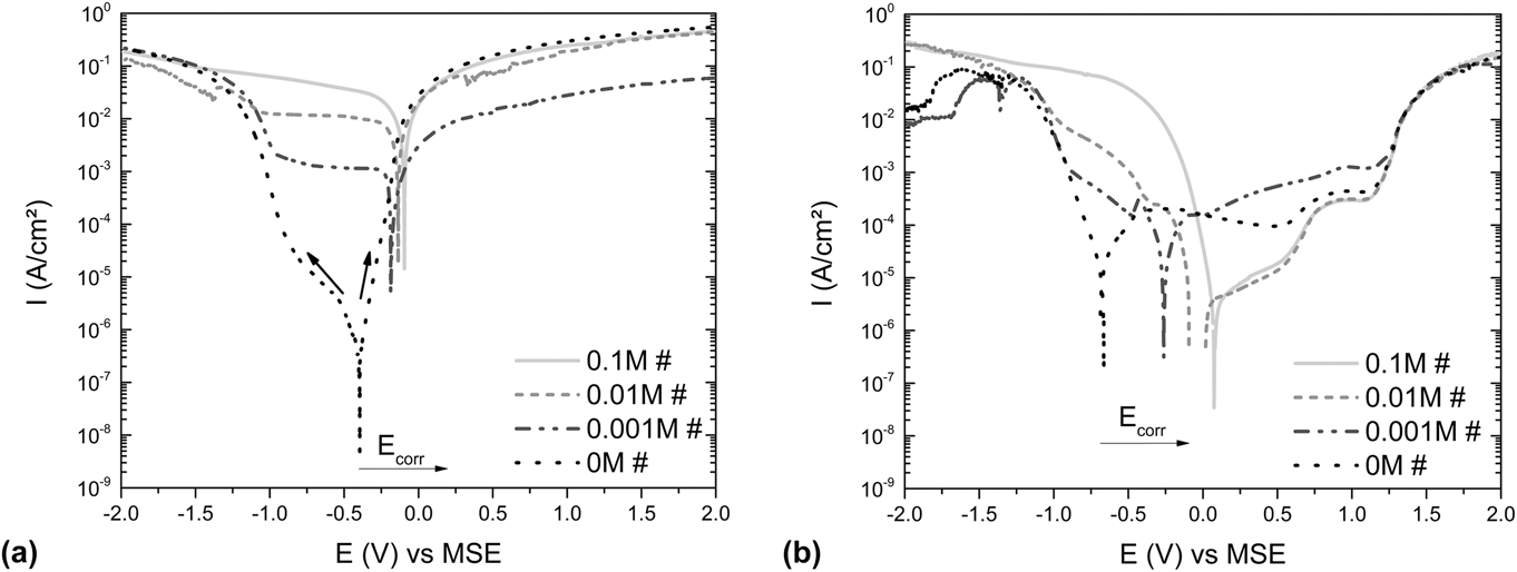
To fundamentally characterize the impact of Fe2(SO4)3 additions on the electrode behavior, potentiodynamic polarization measurements were conducted in 0.1 M H2SO4 solution with different salt concentrations—firstly for the W tool electrode and secondly for the glassy Fe65.5Cr4Mo4Ga4P12C5B5.5 workpiece alloy. The typical measured current density–potential—curves are summarized in Fig. 2.
Current density–potential—curves of (a) the W electrode and (b) the glassy Fe65.5Cr4Mo4Ga4P12C5B5.5 alloy recorded in 0.1 M H2SO4 with different concentrations of the additive Fe2(SO4)3 (#) (scan rate = 1 mV/s, arrows indicate the scan direction).
When comparing the curves recorded for the W electrode, it is evident that with increasing Fe2(SO4)3 concentration in the electrolyte the corrosion potential (E corr) shifts significantly in a positive direction. Simultaneously, the overall current density level increases. This is mainly due to the fact that in the cathodic polarization range between E corr and −1.0 V versus MSE, the current density increases by more than four orders of magnitude, when the salt concentration is increased from 0 to 0.1 M. Upon anodic polarization, the current density is less dependent on the salt addition; only for 0.001 M Fe2(SO4)3 lower values were measured. Altogether, this behavior proves a rigorous reduction of the charge transfer resistance and originates from the substitution of the dominant redox reaction 2H+ + 2e− ⇄ H2 by the reaction Fe3+ + e ⇄ Fe2+. Only at potentials more negative than −1.0 V versus MSE, the incipient hydrogen evolution reaction starts to dominate the Fe3+ reduction. In consequence, the negative bias effect described in Ref. Reference Sueptitz, Horn, Stoica, Uhlemann and Gebert16, which generates conditions for repassivation of the workpiece electrode during pulse-off times of the machining process due to an inhibited charge–discharge kinetics at the tool electrode, is expected to be significantly reduced. Another predictable benefit of the inhibited hydrogen evolution is the suppression of gas bubble formation, which eases the usage of the microtool electrodes by avoiding vibration and deformation.
In the case of the Fe-based amorphous alloy, E corr also shifts in the positive direction due to the increasing Fe ion concentration in solution. So E corr shifts from ∼−0.65 V versus MSE without additive in the electrolyte to the much more noble value of ∼0.1 V versus MSE with added 0.1 M Fe2(SO4)3. Also in this case, a significantly increased cathodic reactivity is observed. The E corr shift is further related to a decreasing level of the current density in the anodic regime. In all electrolytes, the Fe-based glass exhibits spontaneous passivity without indication for active–passive-transition. Further, the curves measured in acid solution with 0.01 M and with 0.1 M Fe2(SO4)3 addition show a gradual increase of the current density in the passive regime starting from a rather low level. This suggests a growing surface layer with an enhancing conductivity or permeability. When immersing the Fe-based glassy alloy in the solutions with high salt concentrations, prior to polarization, precipitations of first cover layers—mixed salt/oxide layers with very low conductivity—are possible. The related blocking of the alloy surface yields the very low current densities in the free corrosion and initial anodic polarization regime. With progressing anodization, a transformation of this surface layer obviously occurs—related to the increase in the gradual current density. In the final passive period, i.e., at potentials larger than 0.75 mV versus MSE a passive current density level similar to that measured with no or low salt content is reached. In the following, the concentration of the Fe3+ solution species has no significant influence on the transpassive regime. It starts in all electrolytes at ∼1.3 V versus MSE. Consequently, for ECMM processing higher pulse voltage amplitudes are obviously not required to achieve the anticipated precise anodic dissolution.
Altogether it is evident that higher concentrations of the Fe2(SO4)3 electrolyte additive reduce the anodic potential regime of passivity of the Fe-based BMG and also suppress the cathodic hydrogen evolution at the W tool electrode in the potential regime more positive than −1.0 V versus MSE by the introduction of the more active Fe3+ reduction. This is especially pronounced for the electrolyte 0.1 M H2SO4 with 0.1 M Fe2(SO4)3.
B. Surface state of the BMG
As already mentioned, the surface state of the BMG workpiece is of particular importance for the success of the ECMM process and is controlled by the environment as well as by the polarization conditions. To investigate the nature of surface layers formed on the glassy workpiece electrode in this study, XPS analysis was conducted. Exemplarily, the alloy samples were exposed under OCP conditions or were polarized at 0.6 V versus MSE for 4 h in sulfuric acid solution without and with addition of 0.1 M Fe2(SO4)3. The polarization potential in the passive regime [Fig. 2(b)] was chosen to be a corresponding value for the bias potential during the micromachining process. XPS spectra have been measured for the initial surface state and after different sputtering steps. In this way, concentration–depth-profiles of the surface states of the differently treated samples were obtained.
It must be pointed out that in the case of the glassy multicomponent alloy, the use of standard single element sensitivity factors,Reference Moulder, Stickle, Sobol and Bomben17 which are used for the quantitative analysis of the spectra and depth profiles, is not satisfying for an exact element concentration quantification of such complex alloys. Further, in the analysis only Fe, O, P, Cr, Ga, and Mo were considered and the given atomic concentrations were normalized. B and C, which are also constituents of the glassy Fe65.5Cr4Mo4Ga4P12C5B5.5 alloy, were not surveyed, because B cannot be analyzed as the higher content of P in the alloy shadows the B peaks and the measured C concentration at outermost surface regions has mainly to be assigned as sample contamination. Despite these restrictions, the resulting typical concentration–depth-profiles shown in Fig. 3 can be used for satisfying qualitative characterization of the surface layer. Figure 3(a) (immersion at OCP) and Fig. 3(c) (polarization at 0.6 V versus MSE) correspond to samples treated in pure sulfuric acid solution. Figure 3(b) (immersion at OCP) and Fig. 3(d) (polarization at 0.6 V versus MSE) correspond to samples treated in the salt containing electrolyte. The surface layer region is estimated from the decaying O concentration.
Concentration–depth—profiles (depth equivalent is about 0.6 nm/min) from XPS investigations of the surface of the bulk glassy Fe65.5Cr4Mo4Ga4P12C5B5.5 samples after various treatments: (a) 4 h immersion in 0.1 M H2SO4, (b) 4 h immersion in 0.1 M H2SO4 with 0.1 M Fe2(SO4)3, (c) 4 h polarization at a potential of 0.6 V versus MSE in 0.1 M H2SO4 and (d) 4 h polarization at a potential of 0.6 V versus MSE in 0.1 M H2SO4 with 0.1 M Fe2(SO4)3.
Similar to earlier studiesReference Chattoraj, Baunack, Stoica and Gebert18 all sample surfaces were found to be covered with a few nanometer thick layers consisting mainly of Fe-oxides or Fe-oxyhydroxides slightly enriched with P-species. The Ga as well as the Cr concentration increase slightly near the outermost surface region and are uniformly low after further sputtering steps. Because of the low Ga and Cr contents in the alloy (both 4 at%) their impact on the oxide layer growth is expected to be not significant. In contrast, the concentration of Mo species gradually increases in the oxide layer region suggesting that Mo plays a specific role in the surface layer formation. The high analysis values of the Mo concentration must be attributed to the already discussed use of the standard single element sensitivity factors or to effects of preferential sputtering.
Comparing the profiles, it is apparent that a sample, which was immersed for 4 h at OCP in the electrolyte with the high salt content [see Fig. 3(b)], has a surface layer which is five times thicker (about 24 nm) than that of a sample immersed in pure H2SO4 solution (about 5 nm) and also than those layers of samples which were anodically polarized (also about 5 nm). Obviously, under OCP conditions, the high Fe3+ ion concentration in the solution yields an accelerated surface layer formation, probably by a precipitation process. But apparently, the anodization with potentials of 0.6 V versus MSE [Figs. 3(c) and 3(d)] does not replicate these results. With respect to the dynamic polarization behavior [Fig. 2(b)], at potentials more positive than 0.5 V versus MSE all passive current density data measured in electrolytes with no or varying salt concentrations tend toward a similar level. This suggests a transfer from initial precipitation layers toward controlled anodic layer growth. So the anodically controlled surface layer growth is more retarded independent of the electrolyte composition.
C. ECMM of model microstructures
In the following, ECMM experiments for producing model microhole structures were conducted in two electrolytes: (i) 0.1 M H2SO4 with 0.001 M Fe2(SO4)3 and (ii) 0.1 M H2SO4 with 0.1 M Fe2(SO4)3. When employing the electrolyte with a very low additive content, machining was only possible by superposing a constant DC bias potential U bias provided by using the potentiostat with the ultrashort voltage pulses provided by using the pulse generator (U off = 0 V, U on = 6 V, t pulse = 100 ns, and t period = 1000 ns.). The applied bias potential prepolarizes the whole workpiece electrode surface, i.e., keeps it under controlled anodic conditions throughout the whole machining process. To reach a noticeable material dissolution, U bias had to be chosen slightly higher than the onset of the transpassive regime (1.3 V versus MSE). But still, the tool feed corresponding to the machining process was strongly limited. Furthermore, the high value of U bias provoked pitting corrosion on the BMG surface.
As expected, the results achieved by using the second electrolyte with more concentrated salt addition have been much more satisfying. It was revealed that a reasonable machining occurs already by only applying the ultrashort voltage pulses provided by using the pulse generator directly between the tool and workpiece electrode with the typical pulse parameters: U off = 0.5 V, U on = 6 V, t pulse = 75 ns, and t period = 750 ns. As the DC bias potential is not needed, a simplified ECMM setup without a potentiostat can be utilized.
Further the pitting corrosion is apparently diminished, but could not be suppressed completely. Applying even lower pulse-off voltages (0.2, …, 0.45 V) could diminish the pitting corrosion further, but it also leads to a fortified passive layer growth during the pulse-off time and therefore, to an impeded machining.
Figure 4 presents a microhole structure machined in the electrolyte with a high additive content and the corresponding hole profile. The machined hole structure [Fig. 4(a)] has a neat rim and smooth walls and reaches a diameter of ∼80 µm and a depth of ∼90 µm (diameter to depth ratio <1). However, the unwanted conical shape of the machined hole is conspicuous [Fig. 4(b)], which is caused by the tip shape of the tool electrode as well as by the continuous dwelling of the bare tool tip region in the surface near region upon progressing machining, which yields not only alloy dissolution at the hole bottom, but also at the hole walls. Besides further improvements of the ECMM setup, as for instance by using a (more) cylindrical tool with isolated shafts, also a low frequent vibration of the tool is proposed as in Ref. Reference Ghoshal and Bhattacharyya19 to realize the generation of ideally cylindrical microholes with high aspect ratios.
Optical micrograph of (a) a microhole and (b) the corresponding depth profile machined on the surface of a Fe65.5Cr4Mo4Ga4P12C5B5.5 BMG sample in the 0.1 M H2SO4 with 0.1 M Fe2(SO4)3 electrolyte with the parameters U off = 0.5 V, U on = 6 V, t pulse = 75 ns, t period = 750 ns, and v z = 0.1 µm/s and a W tool electrode of 30 µm.
Besides the above mentioned problem, the developed setup for ECMM processing is capable of producing microstructures on metal surfaces with very high precision. To optimize the machining conditions, the effect of the single parameters on the hole model characteristics has been systematically analyzed.
As already known from machining experiments with crystalline materials, e.g., as presented in Ref. Reference Lin and Huang20, also in the case of the Fe-based BMG, increased pulse lengths [Fig. 5(a), t p = 50, 75, 100, 250, and 500 ns] or amplified pulse-on voltages [Fig. 5(b), U on = 5, 6, 7, 8, and 9 V] result in an enlarged gap between the machined workpiece area and the tool electrode and thereby, in enlarged hole diameters and depths. A further increase of the pulse-on voltage (U on > 8 V) provokes additionally a corrosion of the surrounding workpiece surface [see U on = 9 V in Fig. 5(b)]. On the one hand, this demonstrates that the machining parameters indeed control the local transpassive dissolution process on the BMG surface. But on the other side, this reveals a deterioration of the machining resolution.
Optical micrographs of holes machined on a BMG surface in 0.1 M H2SO4 with 0.1 M Fe2(SO4)3 using a W tool electrode with a tip diameter of 15 µm and (a) varied t pulse or (b) varied U on.
Other experiments were adjusted with varying pulse-off voltages (U off = 0.3, …, 0.9 V) or tool feed rates (v z = 0.05, …, 0.5 µm/s) but no improvement of the machining resolution was attained. High pulse-off voltages reinforced again the pitting corrosion on the surface, while too small values impede sufficient material dissolution. Further it was found that the tool feed rate has to be chosen to be slower than the local dissolution rate to prevent an unwanted contact between the tool and workpiece. But too slow rates delay the process additionally and should be avoided. For instance, the experiment for manufacturing the complex shape shown in Fig. 6(a) lasted 3 h.
Depth micrographs of two lateral microstructures—(a) smiley and (b) spiral—machined into the glassy Fe-based alloy surface with the standard parameter set (U off = 0.6 V, U on = 6.5 V, t pulse = 0.1 µs, t period = 1 µs, and v z = 0.1 µm/s), the working electrolyte 0.1 M H2SO4 with 0.1 M Fe2(SO4)3 and a W tool electrode.
Considering the results of this parameter study, the most appropriate conditions for ECMM of the Fe-based glassy alloy were identified, i.e., the use of a W microtool electrode, an electrolyte composed of 0.1 M H2SO4 with 0.1 M Fe2(SO4)3, standard ultrashort voltage pulse parameters U off = 0.6 V, U on = 6.5 V, t pulse = 0.1 µs, t period = 1 µs, and a feed rate v z = 0.1 µm/s.
With this standard parameter set, the manufacturing of more complex lateral structures on the BMG surface could be demonstrated. Figure 6 shows two structures—a smiley and a spiral that were machined with those optimum parameters. The feed rate in the x/y-direction corresponds to v z of the established standard parameter set. Depending on the etched W tool tip diameter, working track gauges of about 20–30 µm and the depths between 10 and 30 µm were reached. The rim of the manufactured structures is precise and the workpiece surfaces as well as the machined areas are smooth.
The evaluation of the surface quality of the machined areas of Fe65.5Cr4Mo4Ga4P12C5B5.5 glass samples was done by means of SEM examinations. Figure 7(a) shows an enlarged image of the surface morphology of a line fragment belonging to the complex lateral structure shown in Fig. 6(a). The local electrochemical machining process did not significantly change the character of the amorphous sample. The generated cavity had a very smooth surface, which indicates a homogeneous electrochemical material removal by nonselective dissolution. Further, no precipitation of corrosion products was observed. Only a few marked areas (red) with single local heterogeneities are noticeable. However, these heterogeneities appear not only in the micromachined regions. They are visible on the whole cross-sectional area of the bulk glassy sample, which was exposed to the electrolyte. To support this statement, a selected sample was polarized for 4 h at a potential of 0.6 V versus MSE, which matches the pulse-off voltage of the given ECMM standard parameter set. Figure 7(b) shows a magnification of the sample surface. Here inclusions of small crystallites (∼1 µm) are also recognizable—either embedded in the glassy matrix (solid circle) or already corrosively affected (dashed circle). These crystalline defects are present due to unavoidable primary crystallization of marginal Fe-particles during the solidification of the glassy alloy rods. As observed in earlier corrosion studies with Zr-based BMGsReference Gebert, Mummert, Eckert, Schultz and Inoue21 or with other Fe-based BMGs,Reference Gostin, Oswald, Schultz and Gebert22 the interface between the glassy matrix and a single crystalline inclusion is very sensitive to corrosion initiation and propagation leading to an excavation of the crystallites.
Scanning electron micrographs—(a) surface of a machined line segment associated with the experiment smiley [Fig. 6(a)] and (b) inclusions of small crystallites in the surface of a polarized glass sample (polarization 4 h with 0.6 V versus MSE in 0.1 M H2SO4 with 0.1 M Fe2(SO4)3).
The achieved results show that the multicomponent glassy Fe-based alloy with its defect-free single phase nature appears to be ideal for an accurate ECMM treatment. Similar to that of crystalline metals, the strong passive nature of this metalloid containing the glassy alloy, which is beneficial for corrosion protection, is a key problem for micromachining. The successful local dissolution process depends mostly on a sufficient reduction of the passive layer growth in the machined area. Suitable selection of electrochemical processing parameters that induce periodic local transpassive dissolution at a very high rate interrupted by periods of diminished transpassive dissolution yields the best machining precision. Due to nonselective dissolution of the glassy phase, the machined areas are very smooth and homogeneous.
IV. CONCLUSIONS
The ECMM with ultrashort voltage pulses is an appropriate microforming technique for heat sensitive Fe-based BMGs. Former studies in nearly water-free electrolytes showed already that the single-phase glassy structure of the amorphous Fe65.5Cr4Mo4Ga4P12C5B5.5 alloy meets perfectly the demands for a very precise micromachining process. But the anticipated usage of water-based solutions is combined with the inherent passivity of the BMG, which complicates the identification of suitable machining parameters. It was demonstrated that adding Fe2(SO4)3 salt to an aqueous sulfuric acid solution is an appropriate electrolyte choice for electrochemically shaping the Fe-based glass surface. The substitution of the inhibited hydrogen reaction by the Fe3+ + e ⇄ Fe2+ reaction as the dominating reaction at the microtool electrode reduces the charge transfer resistance and in consequence, the disturbing bias potential effect. The salt addition influences also the electrochemical behavior of the workpiece BMG, but not the transpassive regime, which is decisive for the ECMM process.
Optimized machining parameters for the given system consisting of bulk glassy Fe65.5Cr4Mo4Ga4P12C5B5.5 workpieces and W microtool electrodes were identified and utilized in 0.1 M H2SO4 + 0.1 M Fe2(SO4)3 electrolyte for machining of model structures, i.e., microholes and complex lateral line structures. Prepolarization of the workpiece with a DC bias potential close to the onset of transpassivity or the definition of pulse-off voltages in this range upon ultrashort voltage pulsing is effective for suppressing the disturbing passivation of machined areas. Therefore, the microstructures, manufactured with these optimal parameters, show a very high preciseness, appropriate diameter to depth ratios and excellent surface qualities. Furthermore, the modified, environmentally friendly electrochemistry allows the application of a very simple electronic setup, which also yields in a reduced power consumption of the whole ECMM process. With these promising results of fundamental studies, the great potential of electrochemical processing for microshaping BMG surfaces has been demonstrated.
ACKNOWLEDGMENT
We thank Franziska Karnbach (IFW Dresden) for the scanning electron microscopy investigations, Andreas Freidank for conducting the potentiodynamic polarization experiments and the research division of the IFW Dresden for the design and installation of the micromachining setup. We gratefully acknowledge the German research foundation (DFG) for the support of this work under grant Ge 1106/10.